-
1Step 1
To assemble your ATX-Pi you will need the following tools: soldering iron, right angle wire cutters, and a roll of solder. Optional, but encouraged: a PanaVise Jr. or set of "helping hands" soldering clips.
Step one: Place the 330 Ohm resistors on R1-R5 and solder in place. Bending one of the pins on the resistor helps hold it in place.
![]()
-
2Step 2
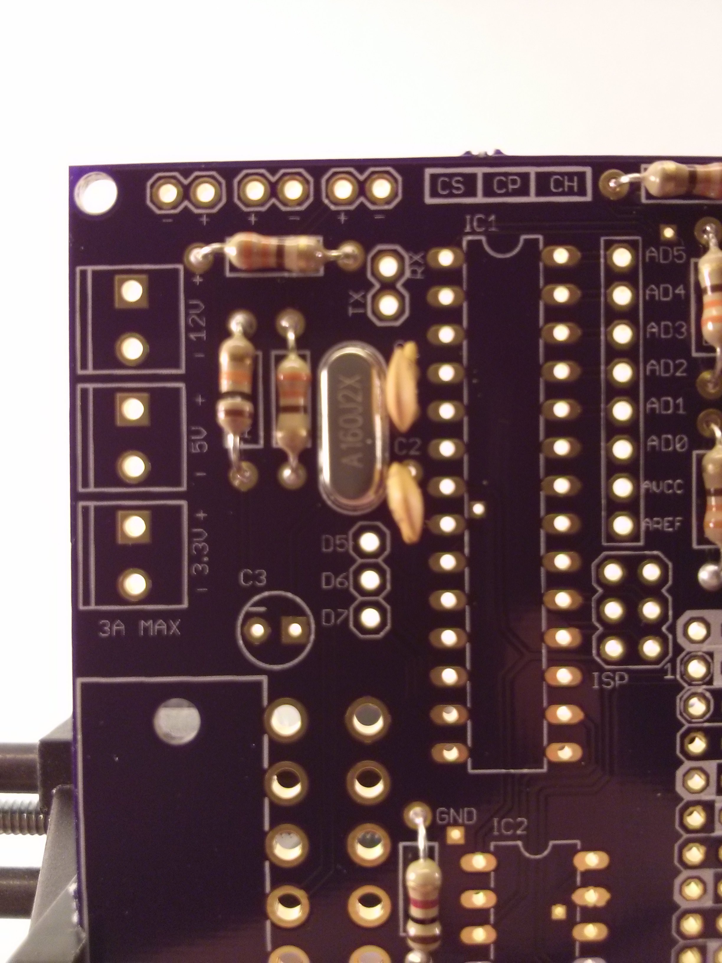
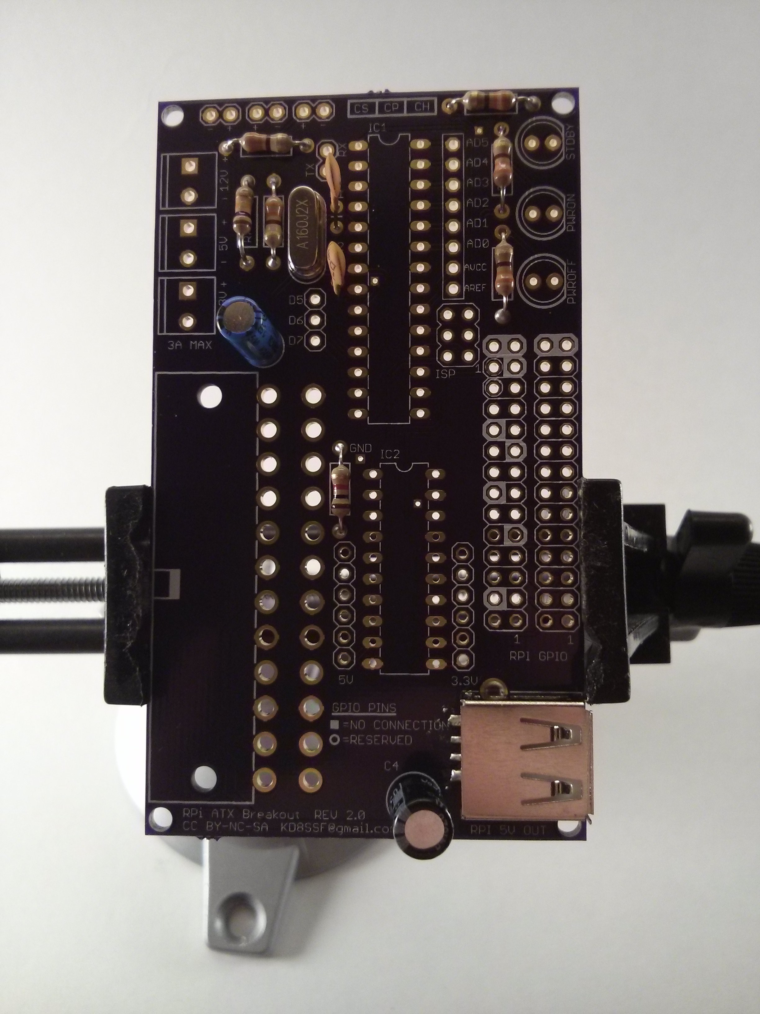
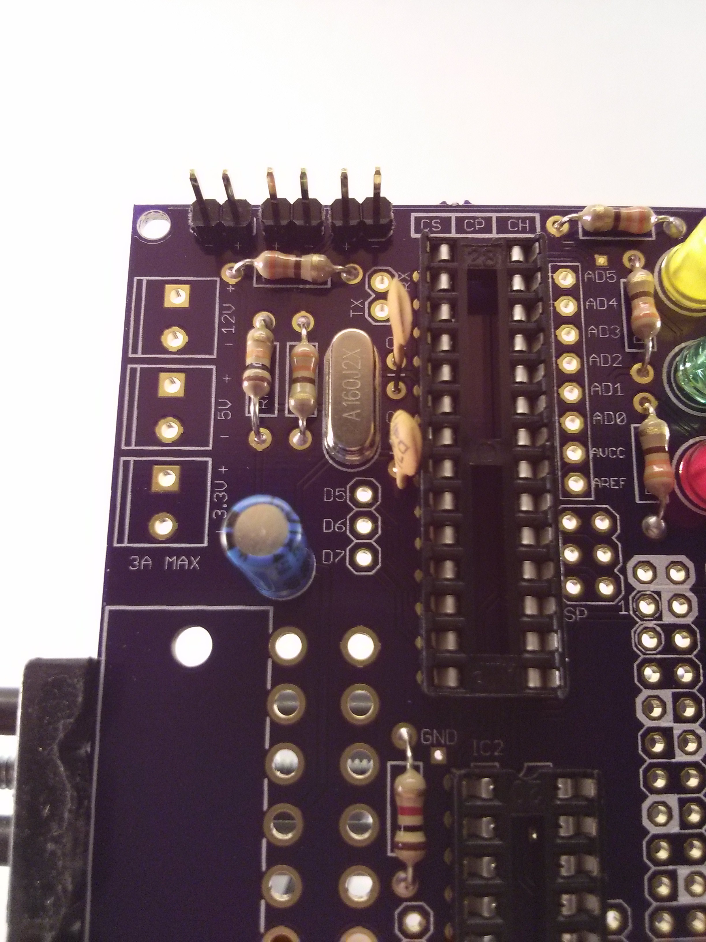
Step two: Place the R6 (1k ohm), R7 (10k ohm), the 16 MHz crystal (XTAL) and the 22 pF capacitors (C1/C2). Solder in place.
![]()
-
3Step 3
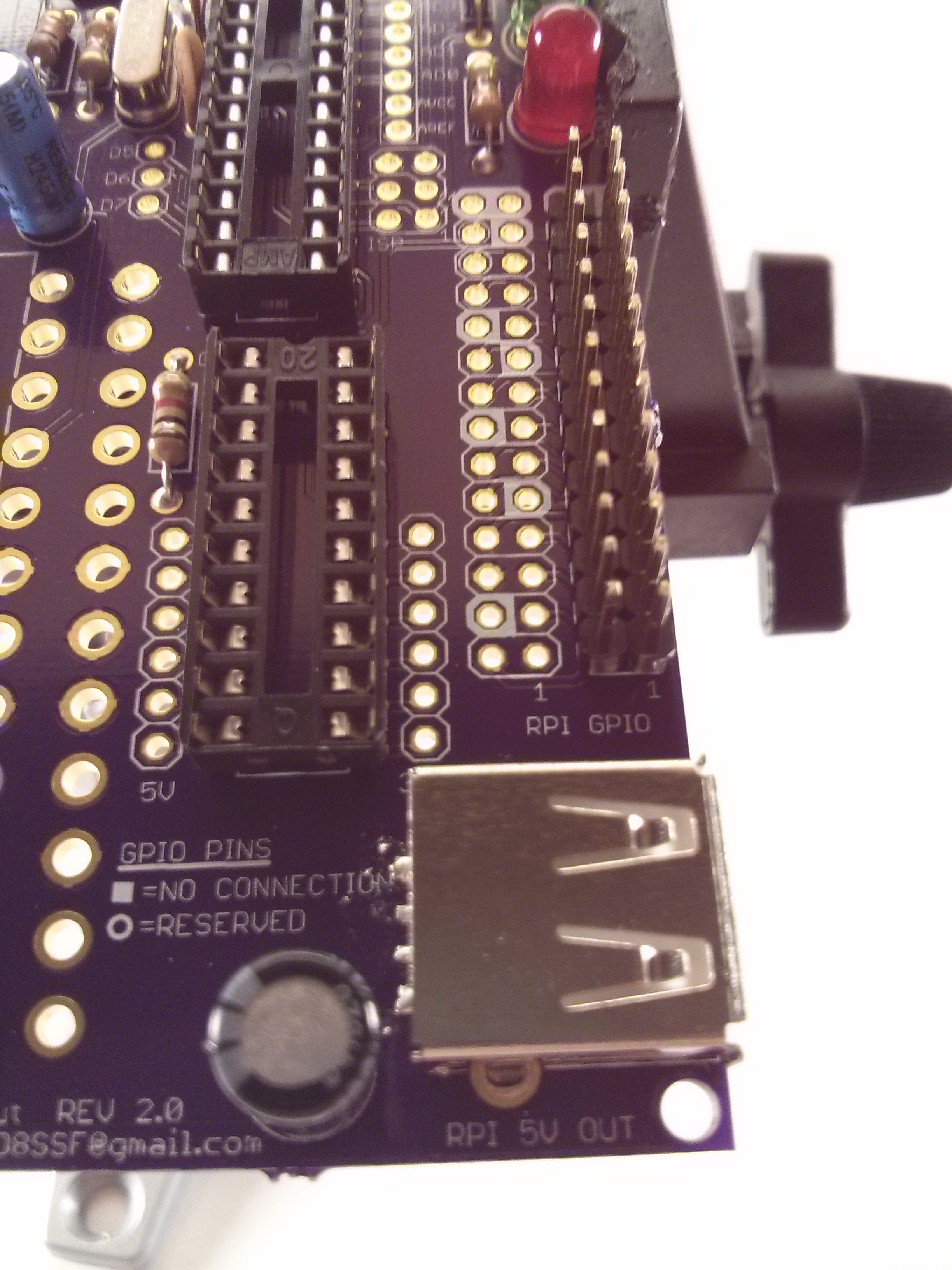
Step three: place the USB-A port on the board and solder in place, starting with the pins on the underside of the board. Next solder the 4 pins on the top.
![]()
-
4Step 4
Step four: place the 10 uF capacitor (C3) and the 100 uF capacitor (C4). Make sure the stripe on both capacitors is oriented to the left, towards the ATX connector.
![]()
-
5Step 5
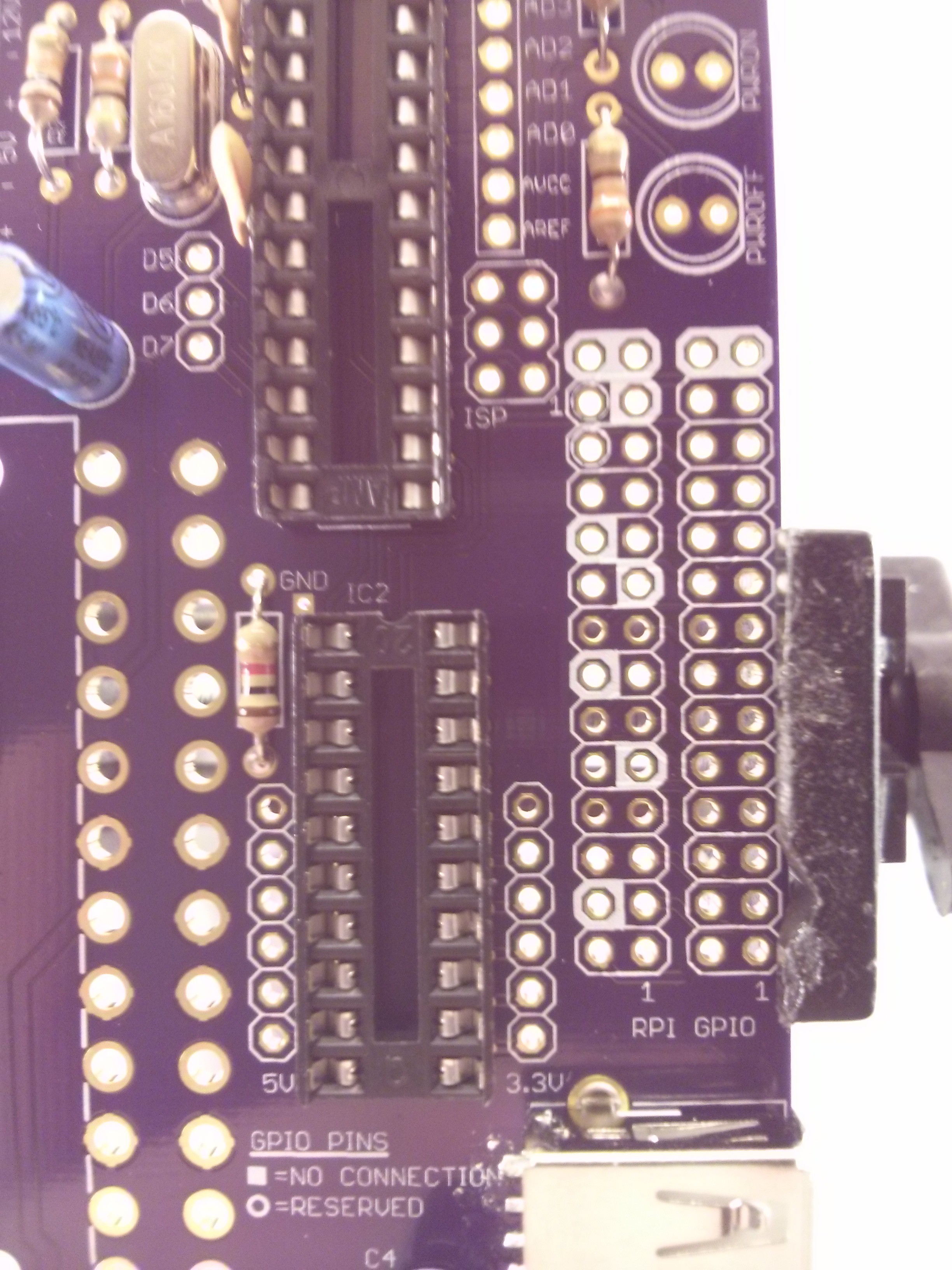
Step five: place the IC component sockets, with the notch matching the silkscreen (pointing up). You may wish to tape them in place until they have been soldered, to keep the sockets level.
![]()
-
6Step 6
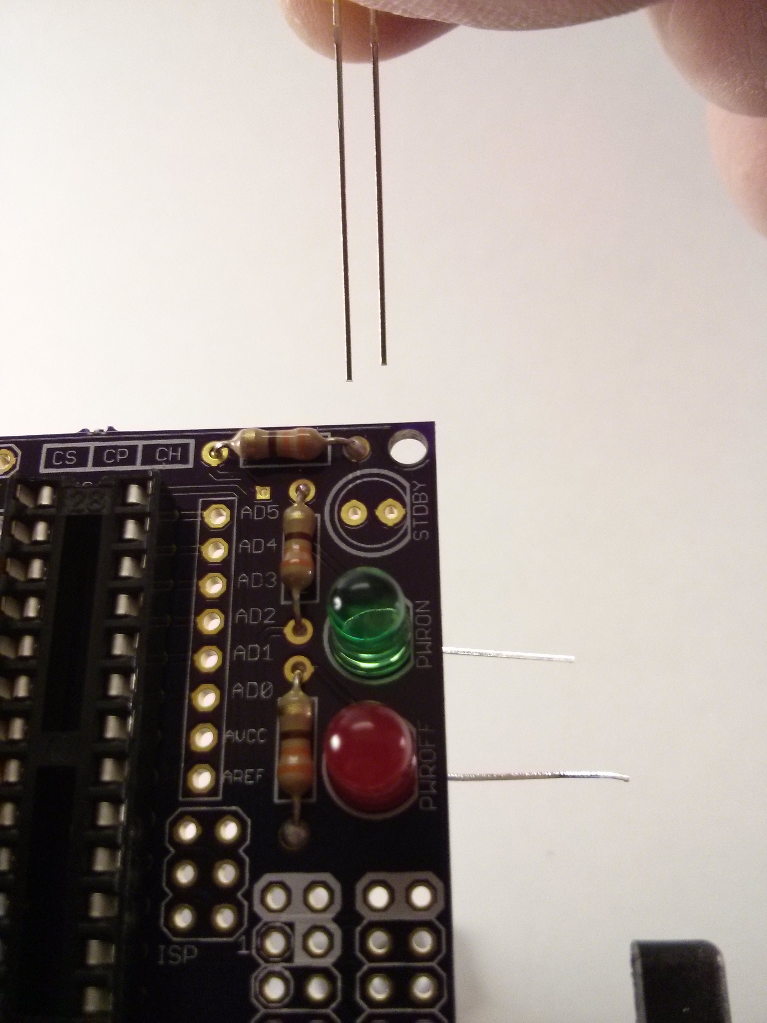
Step six: Add the LEDs, with the short pin facing the outside edge of the board. The notch on the LED should match the silkscreen as well.
![]()
-
7Step 7
Step seven: Add the pin headers for the case switch and LEDs.
![]()
-
8Step 8
Step eight: add two rows of thirteen pins to the Pi GPIO and solder in place.
![]()
-
9Step 9
Step nine: add the ATX connector and solder in place. Make sure the plastic guides snap into place.
![]()
-
10Step 10
Step ten: Place the three screw terminals and solder. Press firmly into the board and they they should stay in place on their own.
![]()
 kd8ssf



Discussions
Become a Hackaday.io Member
Create an account to leave a comment. Already have an account? Log In.