I almost never hand out business cards, but when I do, it would be nice to make an impact. Having seen several other cool PCB based business cards before, I wanted to set out and make one myself.
One problem with a lot of these pcb business cards is that while they did something cool, they still weren't something most people would really use repeatedly. I wanted mine to actually be useful to the person (including those without any technical experience), so they could keep it as a useful tool.
My idea came together as I had been reading up on efficient LED chips for grow light (ie for plants). I have also had a long time interest in practical solar power. And I also like RGB led lights for decoration. A flashlight is something people do use, one that doesn't require a battery change is nice, and one that can make a rainbow of different colors is pretty cool.
That became the concept: place three LEDs of colors red, green, and blue. Connect them to potentiometers to adjust their relative brightness and therefore final color. Power the system with a solar-charged battery.
There are two main design constraints: safety and cost. I don't want this starting on fire, and while it will be much more expensive than a paper business card, it would be nice to keep the cost somewhat reasonable.

This is the simplest circuit I have put on a PCB, but it still has a few quirks to keep in mind.
The solar panel is the most expensive part of the system. Mounting it was a major challenge. I tested a number of different solar panels, read more about that on my original blog post here, and came to the conclusion that the most expensive panel was both the fastest charging and most elegantly mounting of the lot (Any Solar SM141K10LV Monocrystalline Solar Cell 307 mW 6.91 V). However, almost all tested panels work to some extent. If it fits, has an open circuit voltage rating in the ~6-8V range, and produces at least 100 mW rated (the 26 mW tiny one I tried did charge, but not at a practical speed), you could probably use it.
Potentiometers are also surprisingly expensive in both price and board real estate. The ones I went with are being pushed close to their maximum ratings if LEDs are at maximum brightness, a point to note but not an issue so far in testing.
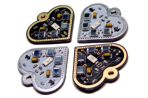
Perhaps the most fun part was designing a footprint that could handle a mix of LED chip sizes (mostly 3030s but also 2835) and then testing a bunch of different LED chips. I tried three different mixes of LEDs:
- The RGB board, with a nice red, a nice green, and a nice blue for adjusting to 'any' output color
- The 'high efficiency board' with highest lm/W for maximum brightness. Digikey helpfully lets you sort many LEDs by this attribute to help you chose. This ended up being a mix of a blue-white (high Kelvin) LED, a red-white (low Kelvin) LED, and a green LED
- The lensed LED board, with LED chips with domed lens that reduce the angle to ~80 degrees, providing a more focused and less diffuse light.
Note the color mixing is only visible on illuminated objects some distance from the board, if you stare at the front of the board your eye will clearly separate the three different LEDs of different colors as there is much more space between them than you would have on say, a color LED display.
I made more of the highest-efficiency board as I thought maximum brightness is the most practical application for most users, although it lost the fullest color mixing ability. With all three LEDs of high efficiency, even without an extra focusing lens, it produces a surprisingly bright light. It won't hold a candle to any commercial, high brightness LED torches, but it is quite usable for many tasks.
The most controversial part of this design by far is the lithium ion charging circuit. Having received reviews on reddit of this schematic and PCB, the two main feedback points were 1) it's not maximally efficient either in voltage conversion or energy harvesting 2) it might not be safe since it...
Read more » Colin Catlin
 Absolutelyautomation
 Open Green Energy
 bobricius