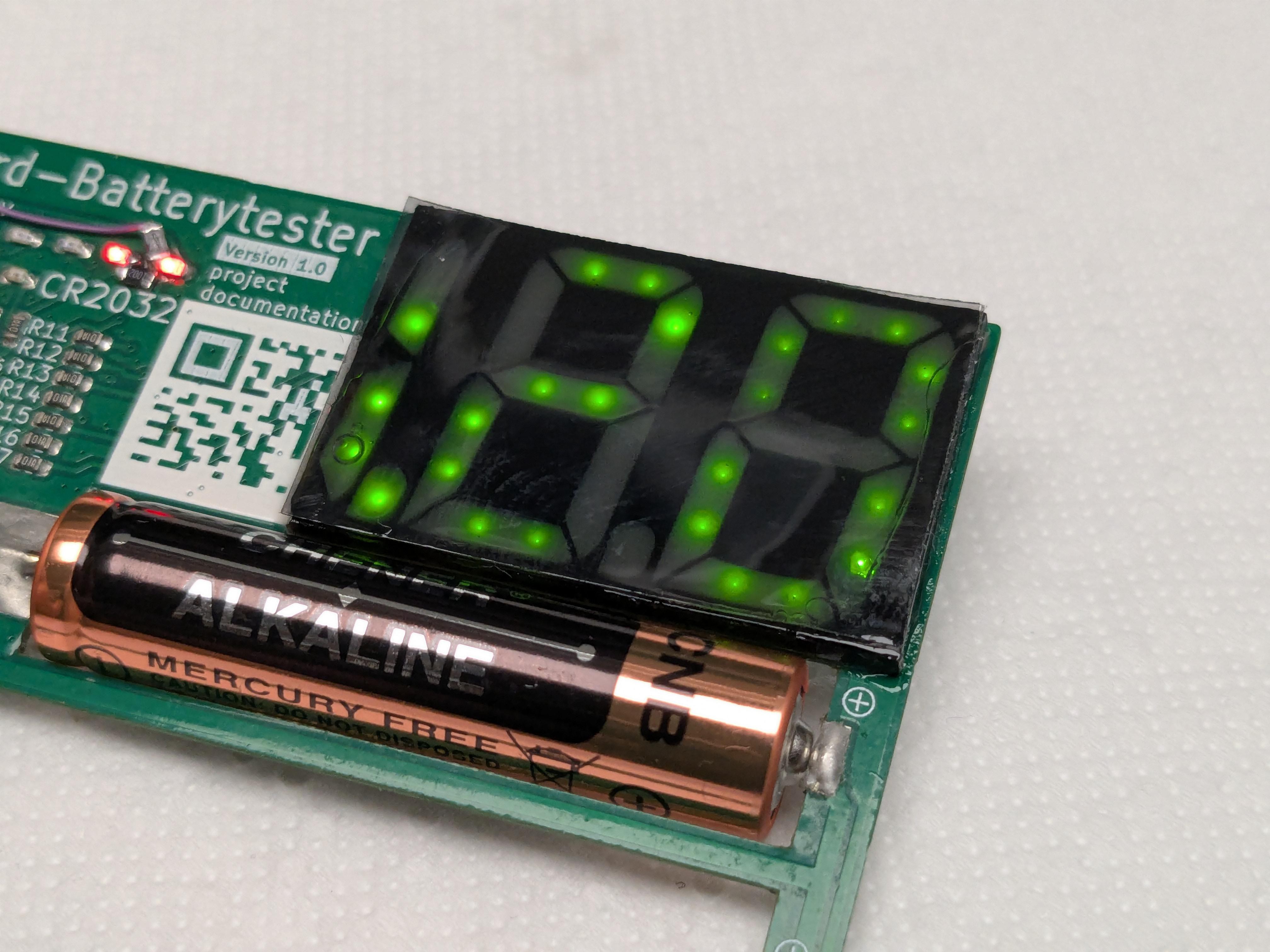
I've wanted to make a PCB business card that's likely to keep getting used, rather than just landing at the bottom of a recruiter's drawer.
A battery tester is something most even non-technical people might actually use, and if you also hand the person a battery to play around with, the 47 flashy LEDs will magically come to life and demonstrate that... well, I can make electronics and demonstrably they sometimes even work.
Oh, and it can test batteries!
Oops! Well, at least now I have a nice example of everything that could go wrong with this concept and can improve with the next iteration.
I'll 3D-print the display thicker for better diffusion, but that will cost brightness. Some more efficient LEDs would be really handy now. The ones in second V1.0 batch should have some 20% more millicandelas per watt, but a 200-300% increase is also possible with just slightly more expensive LEDs. Well, there's V1.1 coming up anyway soo...
I've been holding off on experimenting with improving the display by using milky resin to diffuse the segments and adding a circular polarization film, because like many things, I've wanted to film the process and something was always not ready. Well, the ball is finally rolling!
Seen here:
- the CPL filters I got are not self-adhesive and immediately began warping upon contact with clear resin. - the CPL filters also filtered out a lot of diffused light, so that's just not the way to go. - It's hard to avoid air bubbles in the resin - (for this application) should have gone with emerald green LEDs due to much greater efficiency and thus higher brightness
Less visible: - resin can easily pour out at the edges (happened near the QR code) - the center pieces are wiggly before fully curing, as they're effectively held in place by a compliant mechanism. Need to manually hold them and cure with a flashlight. - the segments aren't perfect due to printing vertically with overhangs. Previous version had a flat piece in the front that prevented a lot of printing issues.
Next I'll experiment with increasing the display thickness from 1.8mm to 3mm. That's as far as I'm willing to go in the name of better segment diffusion.
Well, me and PADS Professional didn't fall in love with each other, so that couldn't last forever.
It just became certain that I'm going back to university! Great news, but that means I'm looking for a part-time job... which in Austria is rather rare, so I should better take any shots I can at standing out among other candidates!
Fortunately, there's a big job faire right around the corner in Vienna, jobmesse austriaon 13-14.09.2025 (the biggest job faire in Austria).
Having expected about 2 weeks lead time on PCB+PCBA, I thought waiting until V1.1 is ready might be a bit risky, so I've ordered 30pcs of V1.0 last Wednesday (27.08)... They're expected to arrive on Monday(01.09)! 🤯.
See you at Jobmesse Austria! I'll bring few extra cards to give out to anyone who recognizes me! 😆
The V1.1 update is due to come out before Career Start 2025, "Austria’s largest Tech-Career-Week" atFH Technikum Wienin 37 days. The first batch might get sponsored and manufactured in Europe by one of JLC's competitors!
5-6 days (including a weekend) from ordering PCBs to getting them manufactured, assembled and delivered is an AMAZING feat, but remember that the first batch did not go as smoothly (2 weeks delay, 12 emails long chain and an extra $18 fee, after I tried to slightly deviate from a standard process to save few bucks on shipping the pogo-pins). You can read the full story in the previous project log entry.
Here's a detailed timeline of the (second) V1.0 batch:
I've stayed up late and placed the order on 2025-08-27, 02:08:31AM local time in Austria (8:08AM in Hong Kong). The clock started ticking. JLC's advertised standard (non-express) lead times are 24h for prototype PCB production and 2-3 days for (economic) assembly.
T+01h39m: They've verified and prepared the design files. T+10h20m: PCBs have entered production and were being drilled. T+26h13m: Final inspection of the finished PCBs.
T+41h08m: Packaging of assembled PCBs T+50h55m: Package ready for pick up by UPS
T+81h17m: UPS picks up the package in Hong Kong T+121h40m: (expected) delivery attempt in Vienna T+121h51m: (expected) driver marks the package as undeliverable, claims recipient is unreachable without ringing the doorbell or calling (because it's UPS) T+129h11m: (expected) delivery to a "Handyshop" instead T+129h24m: (expected) UPS sends an email informing that the package has been successfully delivered T+129h51m: (expected) The Handyshop closes for the day, see you Monday-Friday 10:00-18:00 lol
Each board still needs about 15 minutes of work on my side (inspection, hand-soldering an inductor, soldering pogo-pins sideways, forming battery contacts out of silver-plated wire and soldering those, programming and calibration at first start, test, clipping-on 3D printed parts, pipetting UV resin into display segments, quick UV exposure, placing the boards on a windowsill for few hours to fully cure the UV resin, final test) so it's great to have few days of extra time.
Batteries come in many sizes. Even within one size, for example AA allows +/-0.5mm length tolerance. That's 1mm of uncertainty. It's not much, but enough to make having some sort of moving (or flexing) part essentially unavoidable.
I've tried lots of different design ideas (pics coming soon) for accomodating different battery sizes, including: - Two PCBs riveted together (rejected due to short life span) - Bent paperclip (worked welll but too unprofessional) ...and the pogo pin solution has won.
Okay, pogo pins it is then. Problem is, that's the only part that I didn't already have in stock and would've had to order from LCSC... and I wanted the boards quickly, so DHL shipping it is for this one... but paying that much TWICE, just to also get few bucks worth of 1 item seemed unjustifiable.
Idea: Let's add the pogopins to the board spec and add a note: "No need to solder pogo pin parts (YTC1P-5025-01). Just please include the parts in the shipment."
Well, that didn't work. Board didn't get to production and the next morning I saw a response: "Sorry that we cannot add the parts to clients' parcels since you and us might meet big problems if the customs check the parcels. Could we ignore your remark for this part and solder the parts as your BOM and CPL?"
...what followed was a 12 emails long chain, an additional payment (18$ for 30 boards) and 2 weeks delay, until my boards finally got DHL Express shipped with the pogo pins soldered by the fab.
They actually did a good job for the price. I imagine they needed to re-do some of the boards, as it's very easy to accidentally get solder to flow into the pins and disable them. In fact, 2 out of 30 boards had this issue on at least one of the pins and I don't blame them (I should have specified slightly longer pin variant as per render, thought I did).
I've gone along with the long email chain and all of that, mostly to see what would happen and gain experience for the future. The "special requirement" increased fulfillment time from 2 days to 2 weeks, but they did the job... but then again, 12 emails and 2 weeks, and that was with what I'd call "good communication" and renders like the one below... It's good to know that the option is available, but I know for sure I'm gonna avoid anything non-standard with my future PCB orders.
I'll probably be using Hackaday.io for the more social side and irregularly post major releases here (like, whenever I'll order more cards I guess). Still figuring things out. I've been looking forward to joining the contest and am so glad I didn't miss the deadline.
Thank you! I'll make a post about the pogopins story later today. The display is not the final version yet. It currently uses a single piece of printed resin (mix of transparent and black) and I'm experimenting with diffusing the LEDs a little more, so the actual segment shapes will also be illuminated.
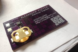
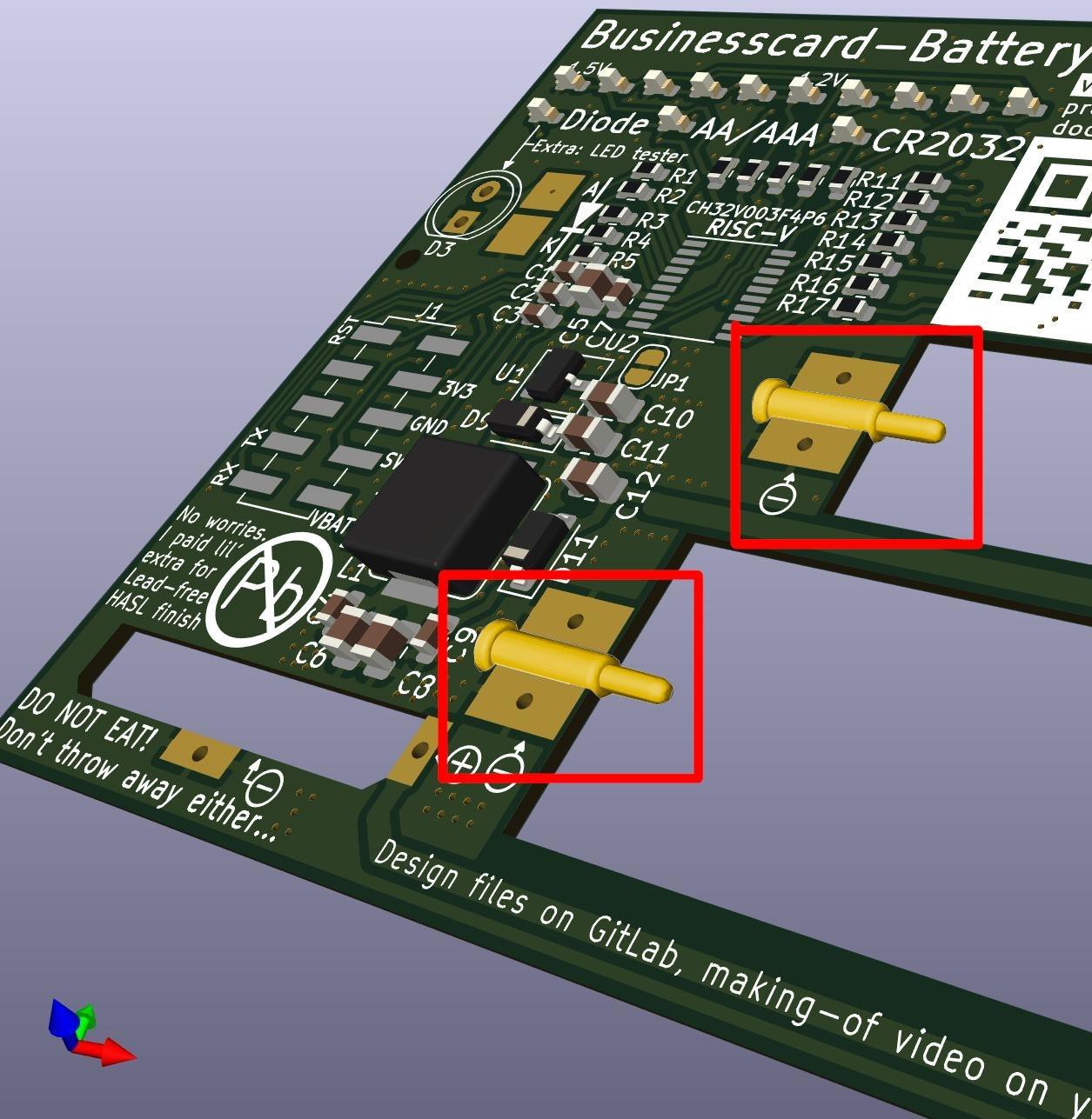
Are those pogo pins soldered sideways? Fantastic idea!
Also good to see: 2 SMD LEDs per segment give a nice look for the numbers.