 tobychui
-
1Sending All PCBs to Print
This project requires PCBs as this circuits are too complex for wiring with UEW. There are a total of 3 PCBs required for this build. Two of them are designed to be stacked on top of each other and the other one is the main controller that require double side soldering / reflow.
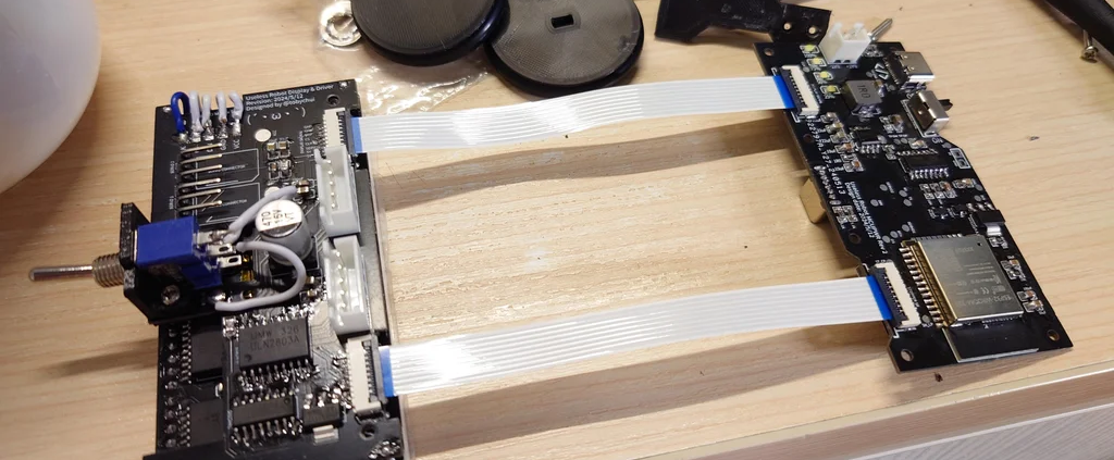
From the front to the back side are the
- LED matrix display module with driver ICs
- Stepper motor driver ICs with shift register, and FFC connectors for MCU connection
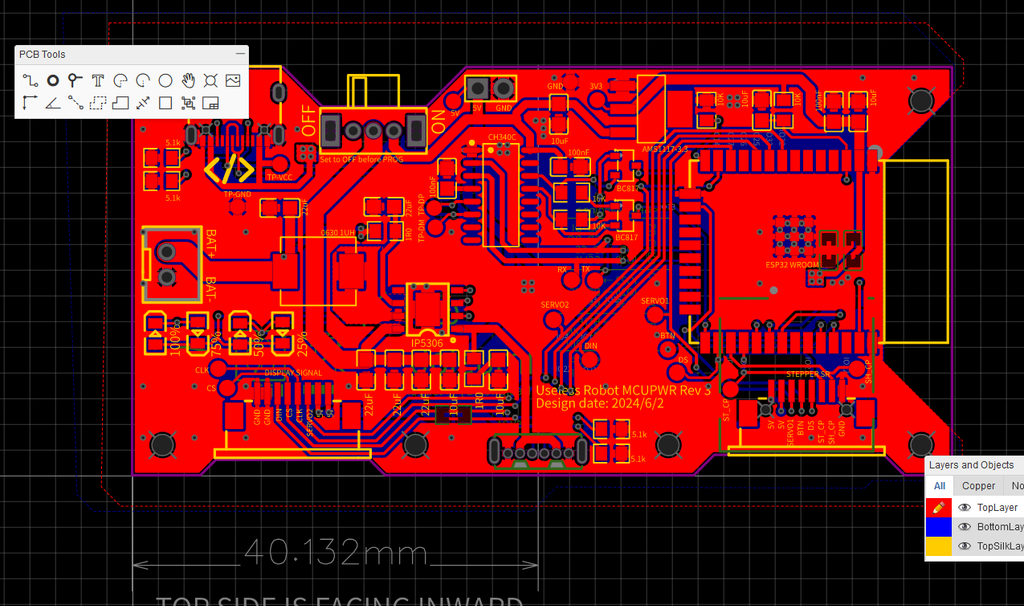
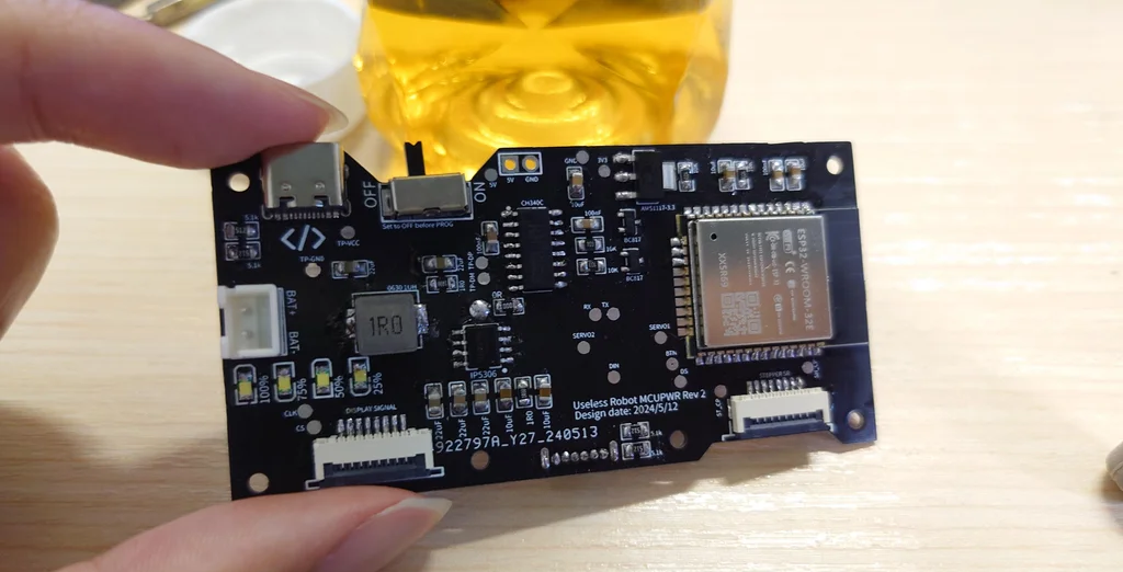
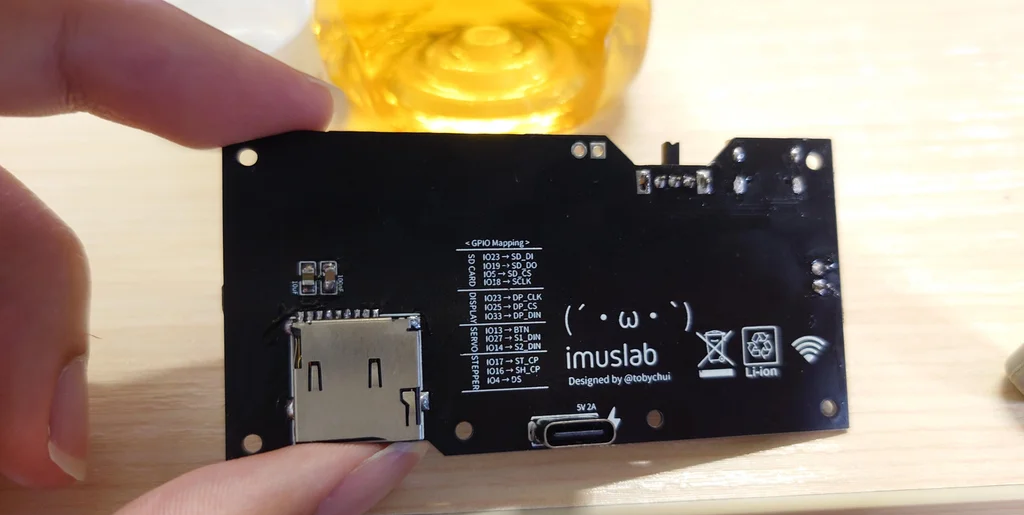
- MCU board, which contains the battery charging and boosting to 5V, USB to UART programming interface (via type C) and the main MCU (ESP32E) with SD card (eMMC) as external storage.
All 3 PCBs are printed using 1mm FR4 to save space.
-
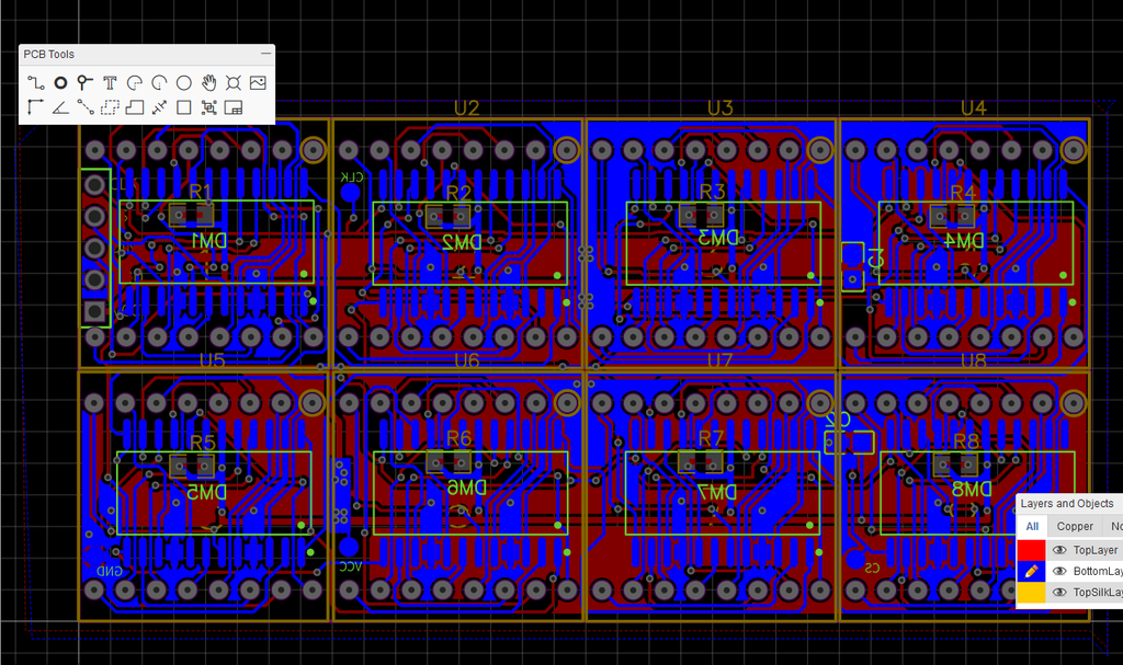
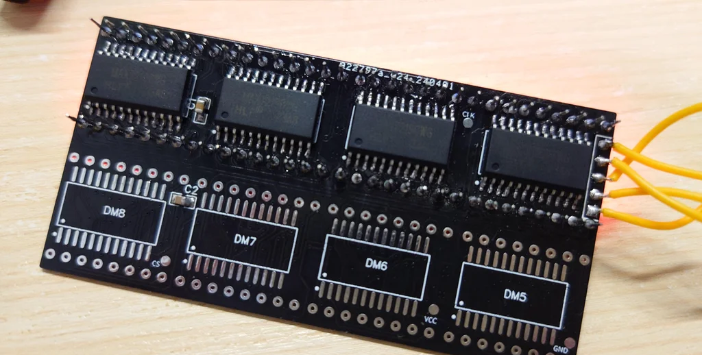
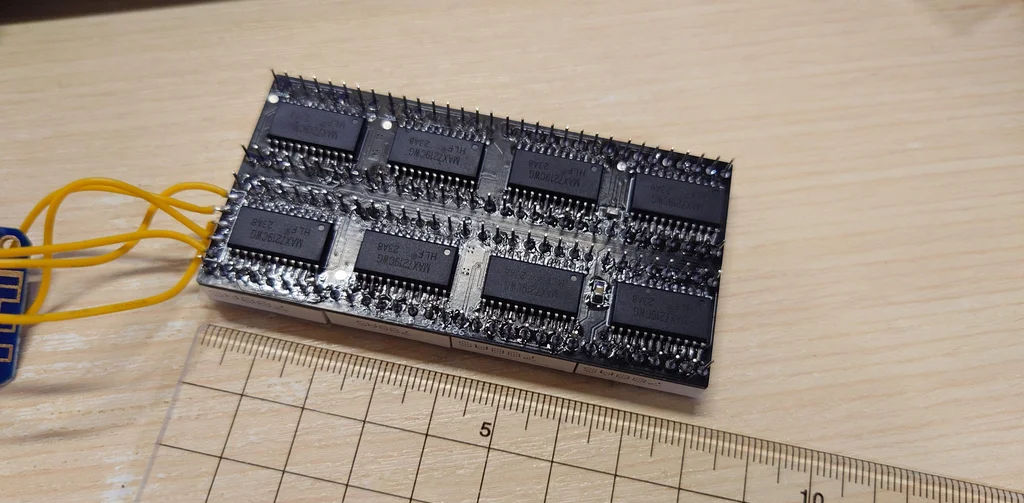
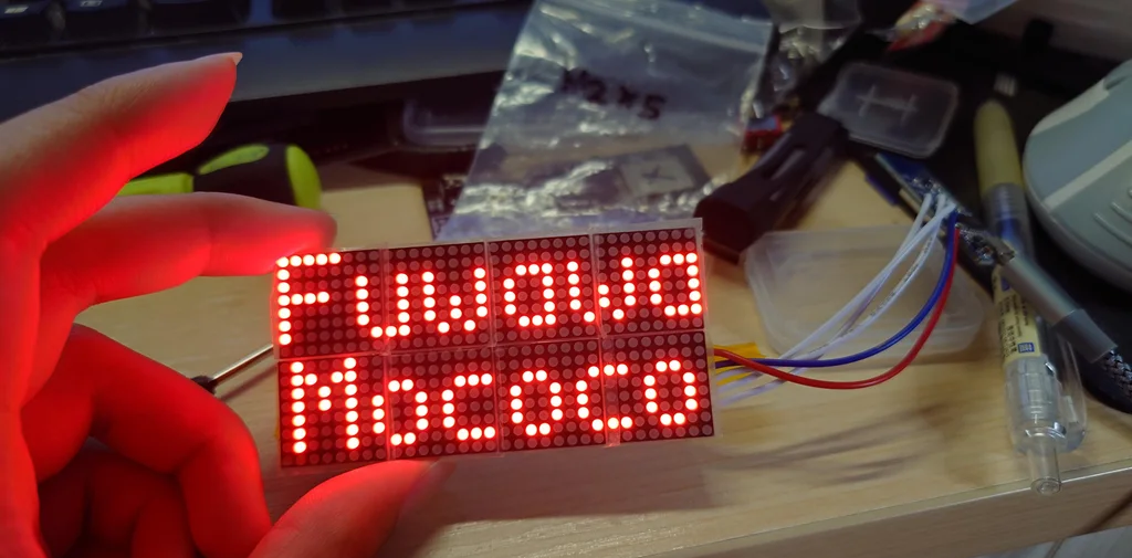
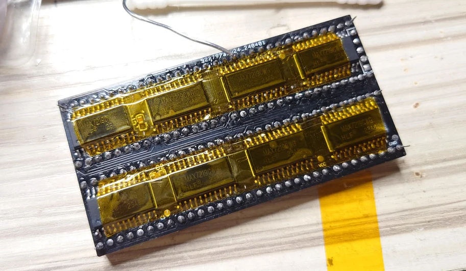
2Soldering and Assembling the Display Module
Let start with the display module. The display module consists of 8 MAX7219 driver IC and 8 LED dot matrix display. The circuit of this module is identical to those commonly available LED dot matrix modules with 8 units in series.
However, as we are using the 1.95mm LED matrix module here, the relative size of the LED matrix is much smaller than those in the 3mm modules. That is why it is recommended that if you want to hand solder this, make sure you solder it module by module instead of face by face. Which means, you would want to solder one driver IC, then one LED dot matrix module, test it with some code on your MCU and if it works, solder the next set. This helps make sure there are no shots or issue with the soldering, as the IC and the pins of the matrix module is so close, after you soldered the 2nd row of the module, it is pretty much impossible to fix the soldering issue on the first row.
-
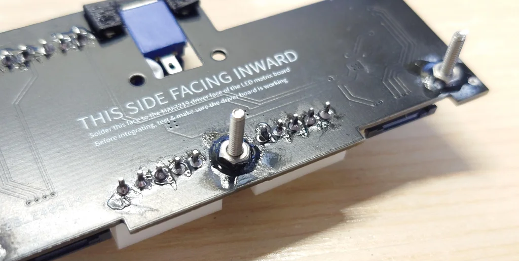
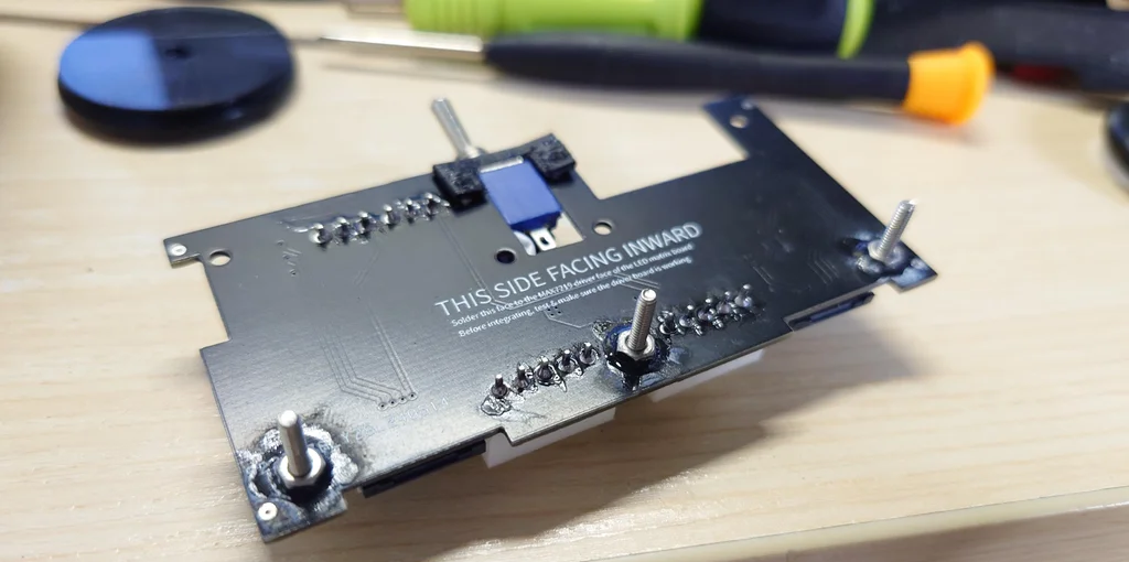
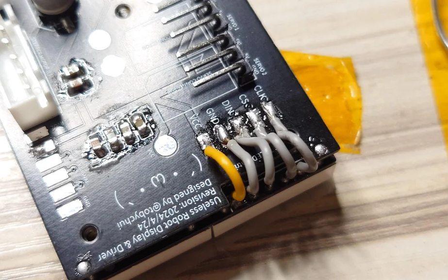
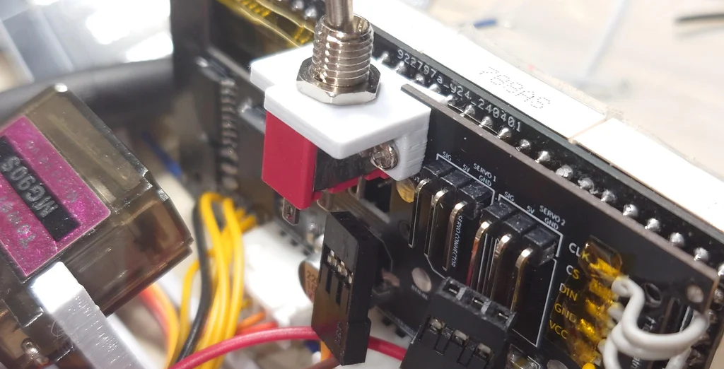
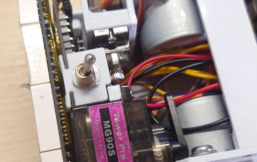
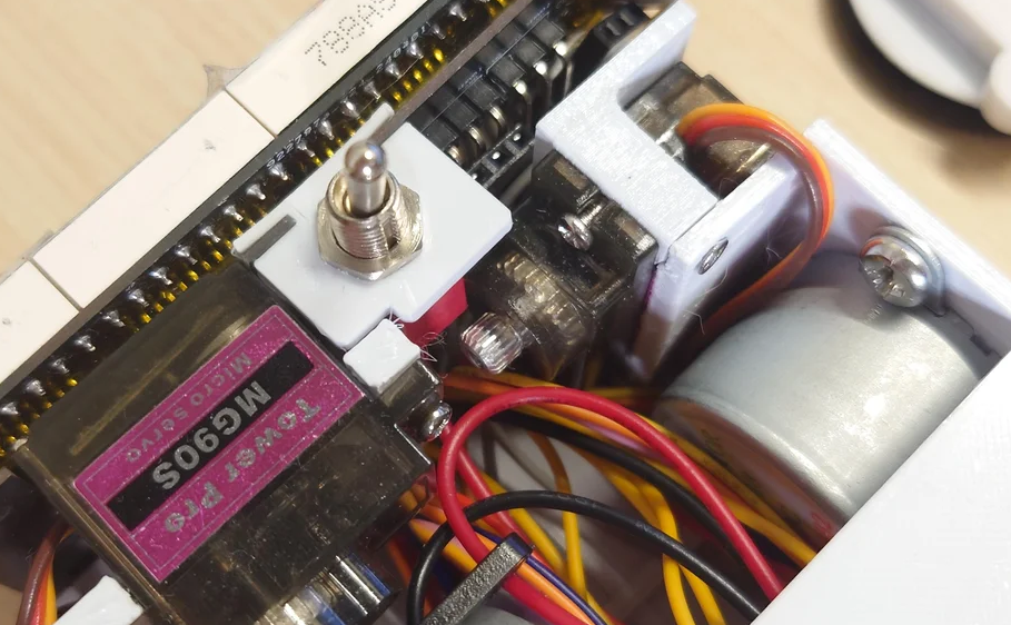
3Glue Nuts Onto the Back of the Driver Board and Install Switch
Before soldering the board,you can take the chance to glue 3 x M2 nuts on the back of the driver board. This will help with the assembly process later on. After the screws are attached and glues are dried up, you can now install the switch. The switch is held in place with 2 x M2 x 5mm srews on both side of the 3D printed mount as shown in the last photo.
-
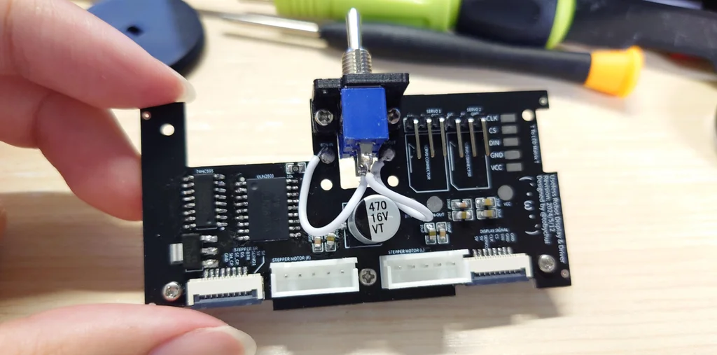
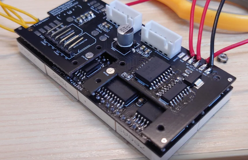
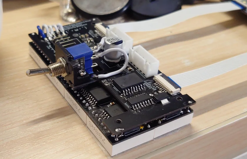
4Solder the Driver Board and Build the Front Assembly
Next, you can start soldering the driver board. The driver board contains the stepper motor driver and a shift register. The shift register will control the signal to the stepper motor driver and allow the MCU to control both stepper motors with just 3 pins. Following that, you might want to put a few Kapton tape and trim away any extruded pins for the next step.
This board is single sided, but you will need to solder it on top of the display module by removing all pins from the LED matrix module on the display PCB and only keeping the 4 pins at the corners. The 4 pins at the corners are required structurally to hold the driver board in place.
After the 4 corner pins are soldered, now you can use a few short wires to bridge the two boards together. The two boards shd be pin-to-pin compatible to the display PCB input and the input of the display PCB will be routed to the FFC connector on the bottom of the driver PCB. That way, both boards can be controlled from the MCU with a pairs of 1mm x 8 pins FFC cables.
-
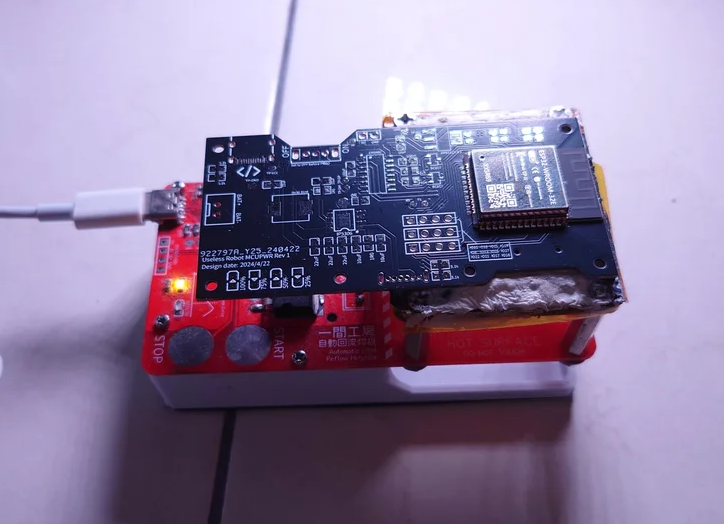
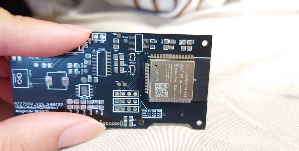
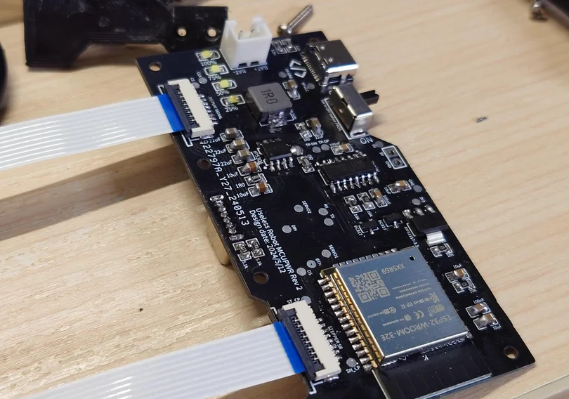
5Reflow and Solder the MCU Board
This is the most complex part in this build, and you will need to populate the whole MCU board manually.
First, the ESP32 contains bottom pads which must require reflowing to solder it. So what I did is I first reflow the ESP32 onto the PCB using my DIY automatic reflow hotplate.
Following that, the IP5306 also requires a bottom pad to be connected as it is in ESOP8 package. So during the reflow process, you can also place one of it onto the PCB and reflow it in one go. Or as my reflow hotplate is just 4 x 4cm in space, I decided with two cycles, where the 2nd thermal cycles solder the IP5306.
After both are soldered, now you can manually populate the rest of the board with soldering iron and other components. This whole process takes me around 3 hours.
-
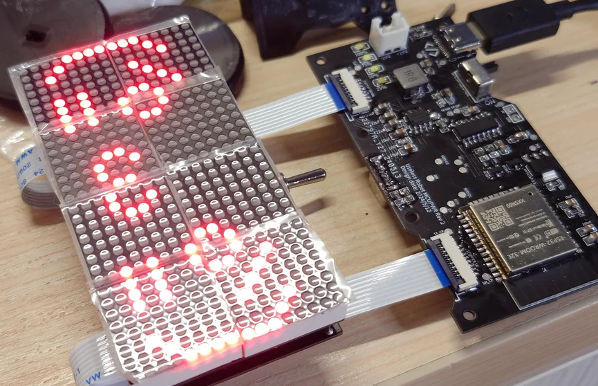
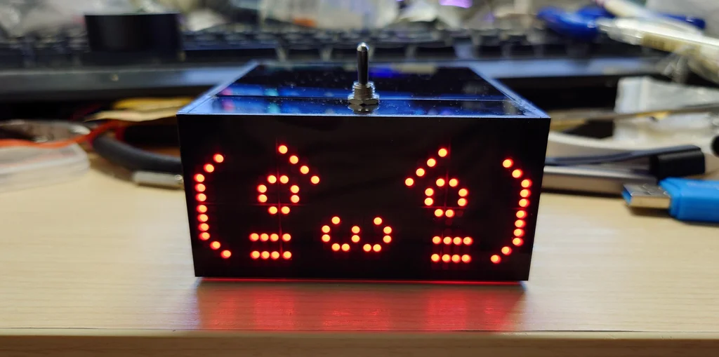
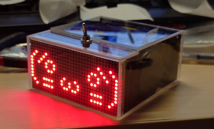
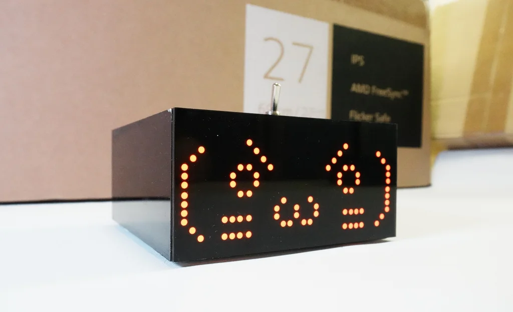
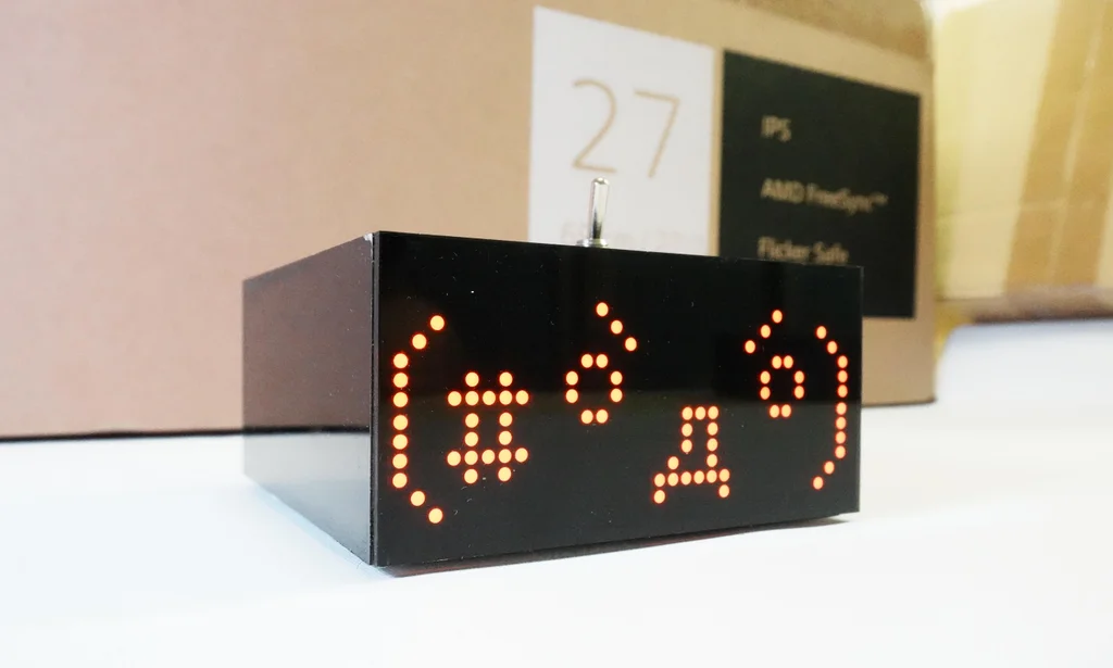
6Functional Test
After all the PCB are competed, you can do a functional testing by connecting the servos and stepper motors to the driver board and connect the driver board to the MCU board. Then, you can flash the testing firmwares into the MCU using the type C port on the top side of the MCU PCB (not the charging type C port at the back) with the SD card slow empty. If everything is working, you should be able to see the default emoji shows up on the matrix display.
-
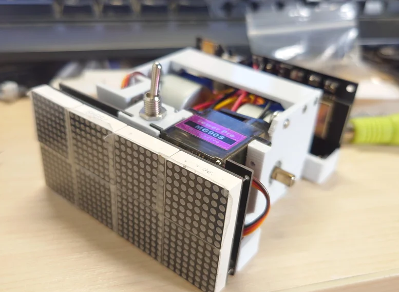
73D Printing Robot Body
The 3D printing body consists of a lot of pieces but you can start by installing the stepper motors and servos into positions. After the servo is screwed in, you will find a L shaped pieces that is use for mounting the vertical switch pushing servo. Screw the L shape parts into the robot body with 3 x M2 x 5 screws.
Next, you can start installing the PCBs to the robot body. I usually start with plugging the stepper motor connector to the front module (the display and driver board) then following by installing the module to the body. The screw holes can be reached from the back side of the robot through the indented part of the wheel compartment.
Finally, you can tidy up the wiring within the body, install the battery (if any) and screw the MCU PCB as the back cover. After everything is done, you should have something similar to the 2nd photo.
-
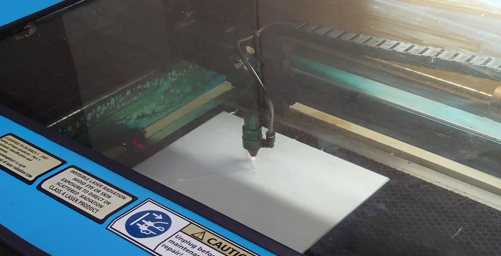
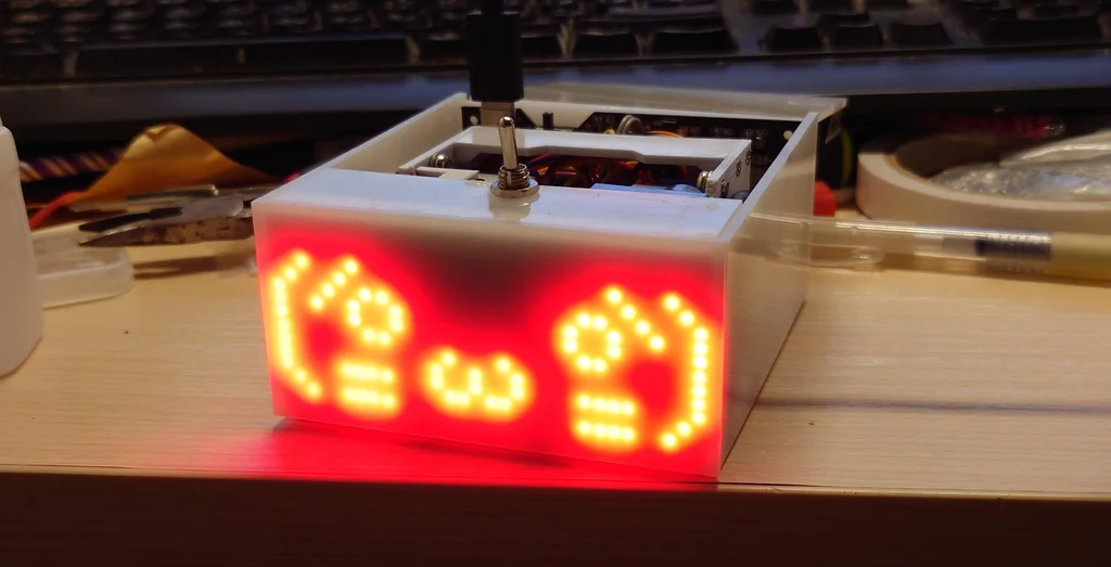
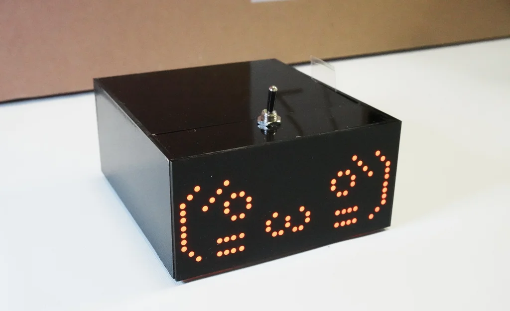
8Laser Cutting the Case
The case is made with black non-transparent 2mm thick acrylic, except the front-plate in which semi-transparent black acrylic was used. You can glue them together with 302 super glue or anything that works. Just to make sure that you remove the protection paper film after all glue dries to prevent any residue stuck on the arcylic surface.
I tried to use transparent and milky white acrylic as well, but it seems semi-transparent black acrylic gives the best results amount all colors.
-
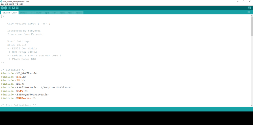
9Firmware Flashing
Lastly, you can flash the firmware of this cute useless robot with Arduino IDE. Pick ESP32 Dev board in the board manager and upload it with Arduino IDE. More settings details are document in the top section of the firmware code.
The source code is available on my Git repo under the "Firmware" folder. See https://github.com/tobychui/Kawaii-Useless-Robot for more details.
-
10Your Kawaii Useless Robot Is Completed!
Now your useless robot is completed! You can use wifi to control it or let it run in automatic mode with different random emotions and response as you continue to play with it. Hope you enjoy this project and see you in the next post!
Github repo link
https://github.com/tobychui/Kawaii-Useless-Robot
Checkout more of my projects
Kawaii Useless Robot - 2024 Edition
A kawaii useless robot that runs away if you push it too hard


Discussions
Become a Hackaday.io Member
Create an account to leave a comment. Already have an account? Log In.