Close
0%
0%

Peace Clock

Design and build a gorgeous, peaceful mantlepiece clock with a hidden mechanism.

Similar projects worth following
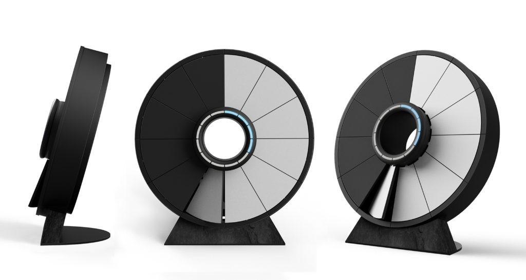
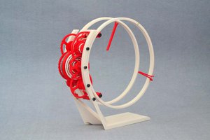
Many years ago I dreamt up a clock whose hands were two glass discs with embossed hands. Instead of being driven from their centres, these would rest on rollers which would both support them and drive them round. This would allow all the timing mechanism to be hidden in the base alongside the rollers while leaving the faces looking simple, uncluttered, and see through.

As I developed the idea I decided that the base too should try to hide the mechanism as much as possible making it simple and possibly even see through too. The clock should seem magic, keeping time with no visible mechanism.

Eventually I found out that this concept had been around a long time, starting with Victorian Mystery Clocks http://electronics.howstuffworks.com/gadgets/clocks-watches/mystery-clock.htm. But I still think my mechanism is unique. But can it be built?

There's so much good stuff in this project! Dreaming up a cool look in glass, chrome, mirrors, gears. 3d design software. 3d printing prototypes. Designing and building a circuit. Programming an embedded controller to keep time.

Prototype 1 was designed to be easy to 3d print. It's nearly made : not entirely successfully but with some good learnings. The motor came geared 240:1 but with 3V input that still made the rollers rotate at 1 or 2 revs per second which is too fast to drive the discs via friction (and unnecessarily fast for minute or hour discs). So I need to design my own lower gearing. Enter Wikipedia!

https://en.wikipedia.org/wiki/Cycloidal_drive

And

https://en.wikipedia.org/wiki/Epicyclic_gearing

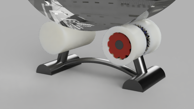
This means larger rollers in prototype 2 which gives me a chance to reduce two motors in the first prototype to one, hide it inside the first roller along with all the gears to drive both disc, and potentially hide the electronics in the second roller.

  • 2 × Discs, glass or perspex, with embossed hands
  • 2 × Rollers, split with front and back rotating independently
  • 1 × Base assembly, supporting the rollers and discs
  • 1 × Motor driving rollers
  • 1 × Circuit board

View all 8 components

  • Prototype PC3: Enter the Stepper

    terryspitz07/20/2017 at 03:53 0 comments

    Somewhere between my original idea for the clock, thinking I would never ever be able to build it myself, then one day realising it was just the excuse I needed to justify buying a 3D printer, and the fun I'm currently having with Fusion 360 and my Prusa Mk 2, I tried building a first prototype in Meccano.  Yes, I still have the Meccano set from my 8th birthday!  

    I wanted to start from first principles, and that meant building a driving mechanism using the simplest electro-mechanical device I could think of: an electromagnet.  I thought that I could use this to drive the clock mechanism via some sort of ratchet pushing round a gear.  Turns out winding your own electromagnets is a very efficient way of running down batteries.  And it also turns out that someone's already done the job of turning electrical power into movement in a very efficient package: it's call "the motor". 

    Protoype PC1 used a motor with 300:1 geardown, which almost worked.  In PC2 I tried simple (cheap) motors and building my own gear train (not enough power to drive 3D printed gears).  In PC3 I've decided to try a Stepper motor.  This is going to give me the precise control of rotation that every clock needs (removing the need for the photodetector in PC1).  Plus with the right input pulses it can turn arbitrarily slowly, hopefully allowing it to drive rollers and the discs without needing an additional rubber sleeve to increase friction on the surfaces.

    I even found a tiny stepper - perfect for fitting inside the roller and even reducing it's size again.  And there's even one with its own 240:1 gear train: http://m.dx.com/p/15mm-2-phase-4-line-micro-15by-dc-5v-stepper-gear-box-motor-355421.  All for $6 (plus postage from Hong Kong).

    It was relatively easy to get this working with my little ESP8266 Arduino (once I remembered its physical pin labelling is different from that in the program) - just #include "Stepper.h"!  Oh and an L293D motor driver chip helps too, with separate power supply to avoid dropouts to the chip power.

    Cool.  Now onto the next step: another new roller design, and how about a new overall clock design to add to the challenge!

  • #inspiration

    terryspitz06/03/2017 at 13:20 0 comments
  • PC2 Travails

    terryspitz06/03/2017 at 10:20 0 comments

    H everyone! (all 52 followers!)

    My last few month's efforts on Prototype 2 to build my own planetary/epicyclic gear train is almost at an end :(. But more later.

    Firstly I videoed Prototype 1, let's call it PC1, in it's latest, almost working state:


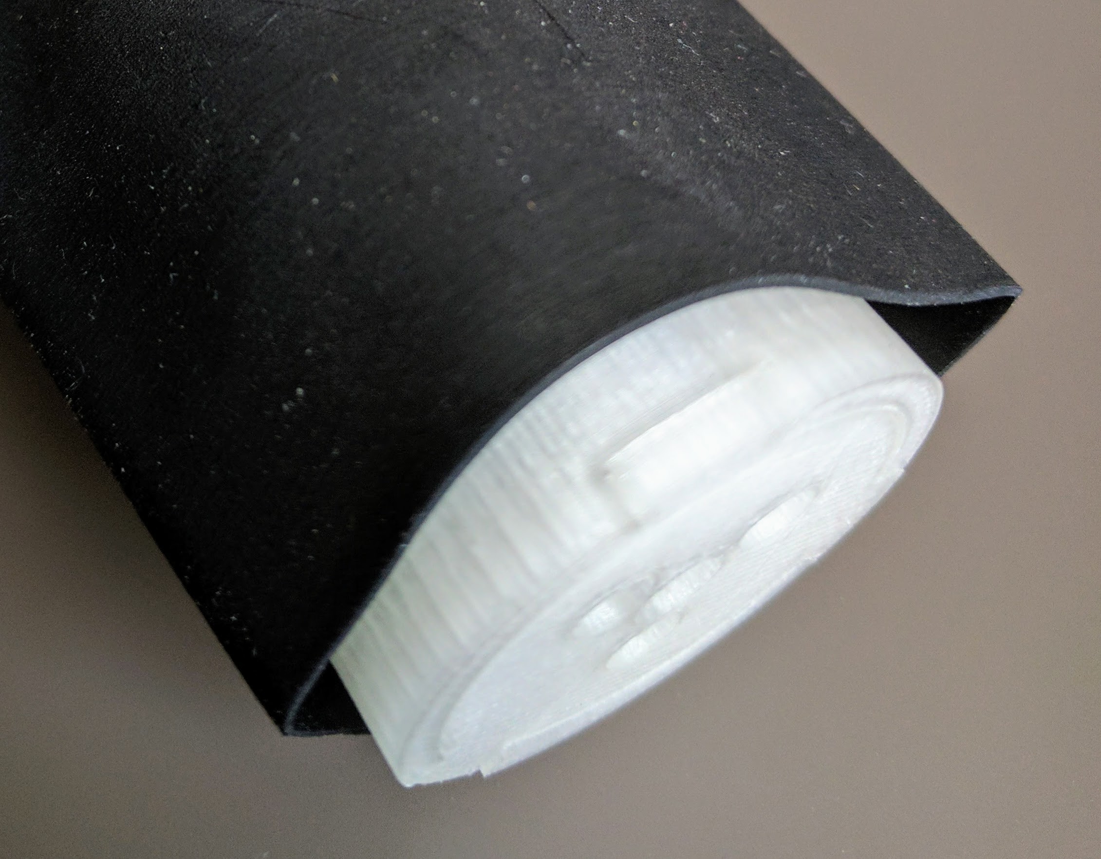
    You'll note the shadow of my fingers pushing it round as the roller doesn't have enough friction to drive the clock face disc. I have a potential solution to this courtesy of my brother the engineer: heat-shrink plastic sleeve:

    Unfortunately the one sample sleeve he has fits perfectly around this larger roller (30mm) from PC2, but not the smaller 20mm roller from PC1, so i couldn't try it. Anyway given the noise and size of the motor with the built in gear down in PC1, i'm now moving onward and upward - so this idea stays on the back burner.

    So what of PC2: building my own complex gear mechanisms...? More "learnings" here.

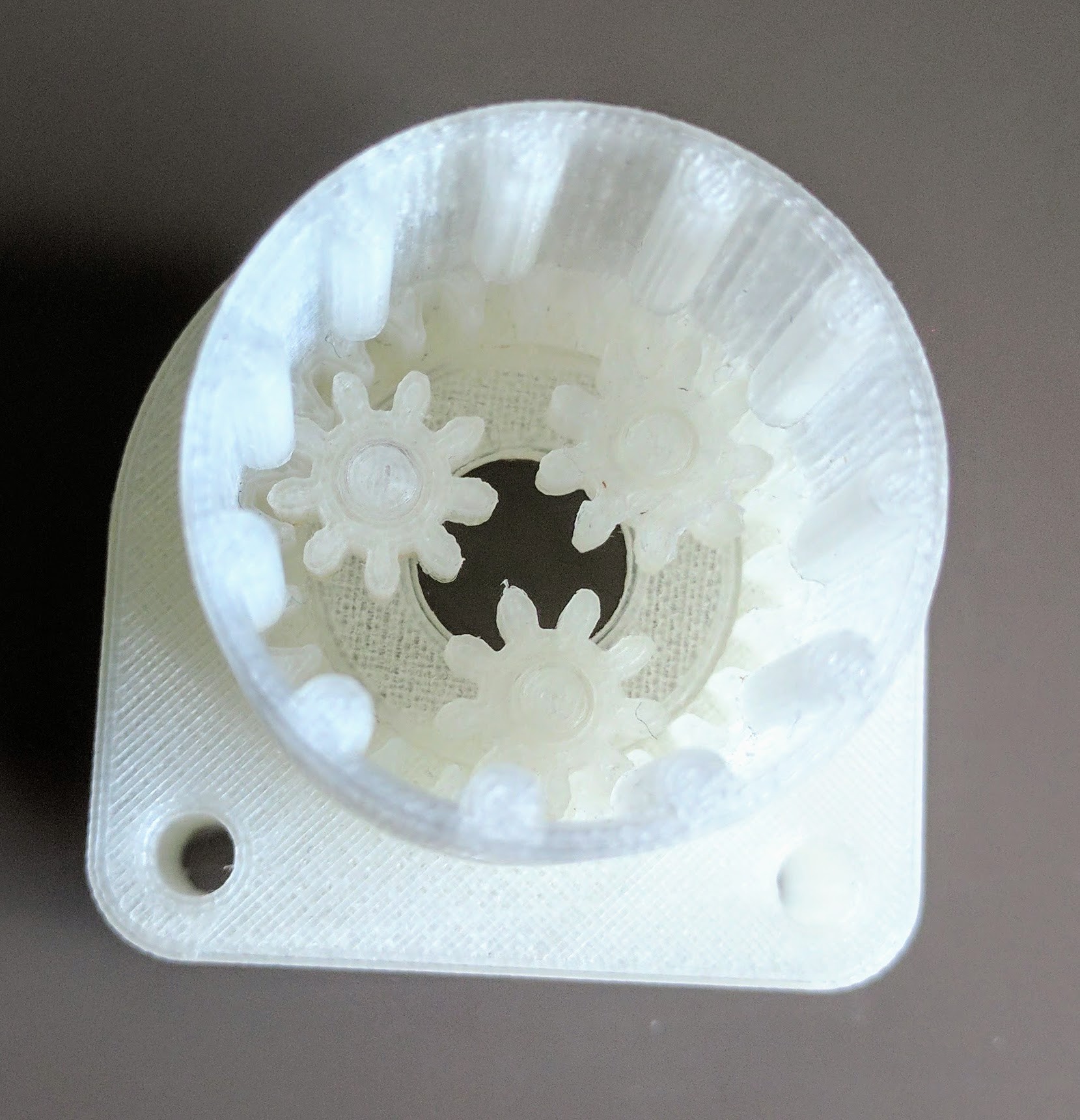
    The main new idea in this design was to hide a gear chain inside the roller mechanism, which it achieves:


    These print mostly nicely on my Prusa Mk2 (once it'd put a cardboard box around it to protect it from drafts):


    Then the nasty engineering details enter the fray. The gears don't turn completely freely due to slight inconsistencies in the printing (visible by eye). Reducing the 'wall thickness' on the Cura slicer helped slighly. Also slowing down the head speed while printing (e.g. 80%).

    But my little motor doesn't have enough torque to push past these so it always quickly jams. Last ditch attempt: helical gears which might avoid the jamming. Other suggestions welcome.

    Otherwise i have prototype PC3 in planning: give up with cheap motors and switch to a Stepper motor: offering precise rotational control and high torque.

    https://www.rapidonline.com/rvfm-my3002-mini-hybrid-stepper-motor-size-11-37-0508

    It's even bigger than the little motor, so the rollers are going to have to get bigger again - but that's just an opportunity to redesign the overall clock shape once again!

  • Gear trains

    terryspitz02/20/2017 at 19:22 0 comments

    I've spent the last few weeks designing a new gear train for the rollers.

    Prototype 1 used a small motor with built in gearbox :

    37-1216RVFM Right Angled Motor and Gearbox 1:220
    £1.64

    This was mounted through the rear base part with the motor protruding into the gap between the front and rear base parts. The gearbox output at the back was attached to one gear meshing with another gear driving the roller. Incidentally the second gear also had vanes which could block the photodetector, allowing the circuit to measure rotations.

    Taking apart the gearbox showed 4 plastic gears, with maybe 4:1 ratio each (4*4*4*4=256). These gear teeth are tiny, perhaps 0.25mm which are too small to accurately 3d print. Also the gearbox is large (20x30x10mm) so would be good to remove it if I can replace the mechanism myself.

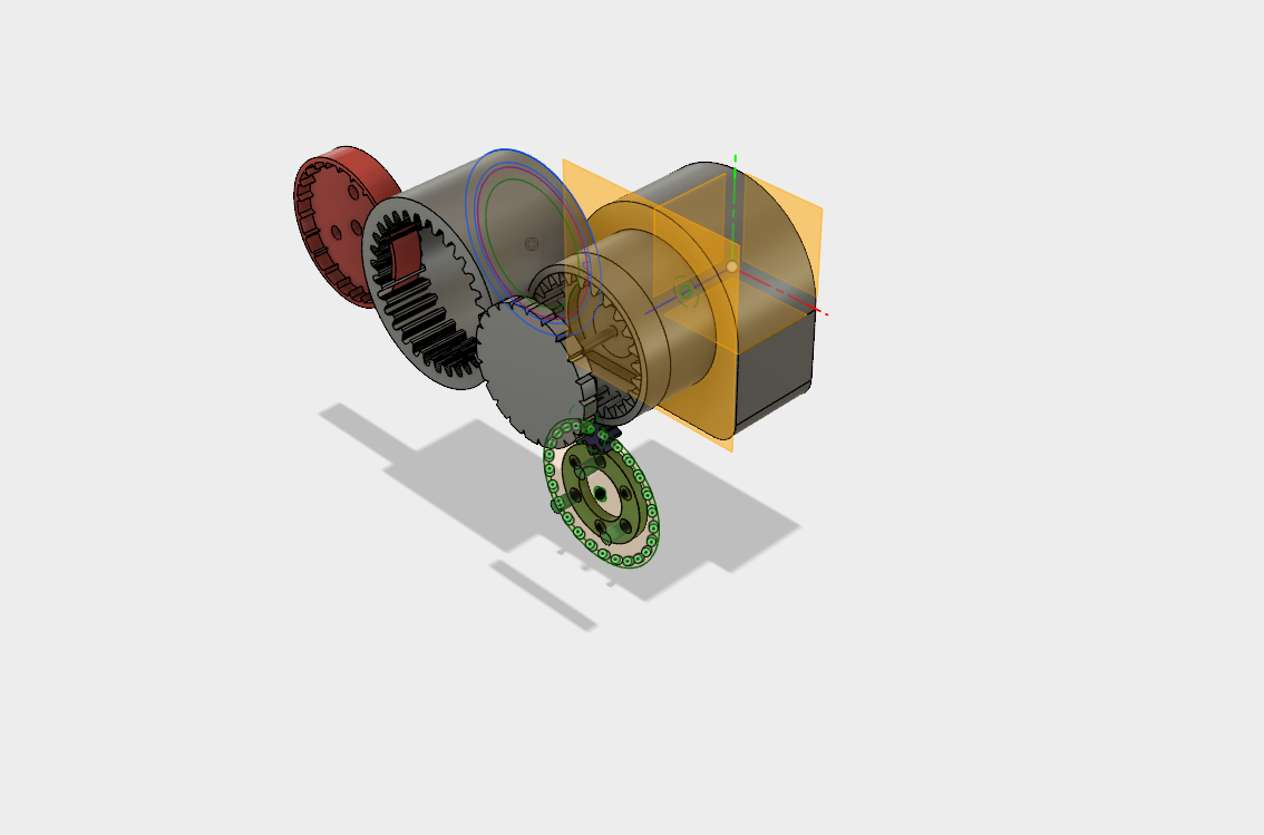
    Also even the 220:1 gear ratio left a rotational speed of about 1 rev/sec, too fast. I need another factor of 5 slower, around 1000:1. Googling tells me there are two gearing mechanisms that might help : planetary gear sets, and epicyclic gears. In fact I think I'm going to use both : planetary gears to provide an initial 5:1, then another 400:1 from a linked pair of epicyclic gears. And all this from only a few pieces : the raw motor with gear, driving three planetary gears, within 1 ring gear cut into the case, the planetary carrier attached to a cam, which rotates a joined pair of epicyclic gears, one rotating against the case, and the other side rotating againt a ring gear attached to the first roller.

    Picture from Fusion 360 here!

    Inspired by Oskar van Deventer's Extreme Reduction:

    Electronics will control the speed or the duty cycle of the motor to drive the minute disc.

    A second epicyclic gear drives the hour disc at a 12:1 ratio. Voila!

View all 4 project logs

Enjoy this project?

Share

Discussions

Similar Projects

Does this project spark your interest?

Become a member to follow this project and never miss any updates