Close
0%
0%

The Outlander Cyberdeck

A handheld fantasy console built around CM4 form-factor SoMs, featuring multiple radios and a physical keyboard.

Similar projects worth following
Logs detailing the design, prototyping, and construction of a custom handheld console

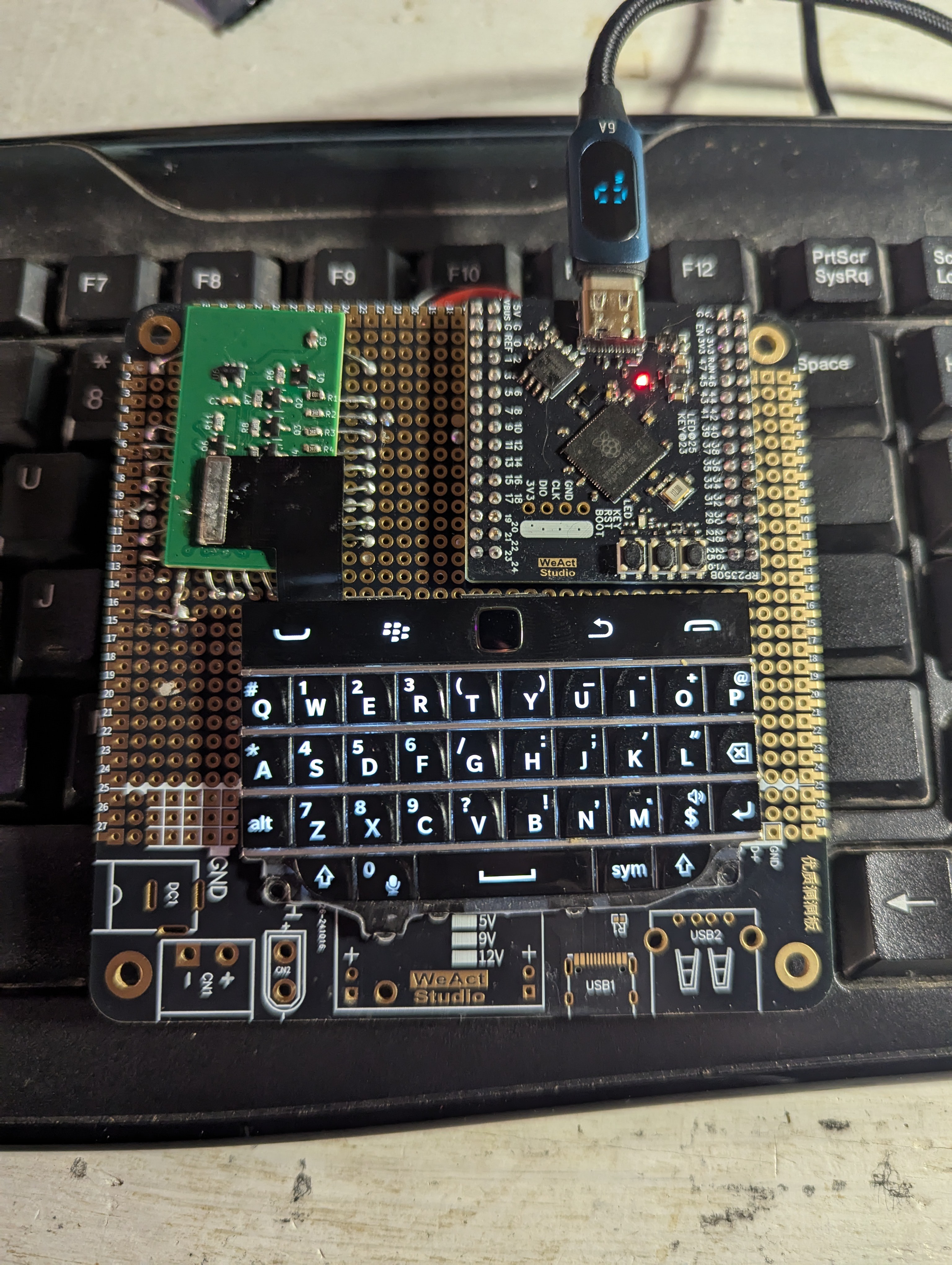
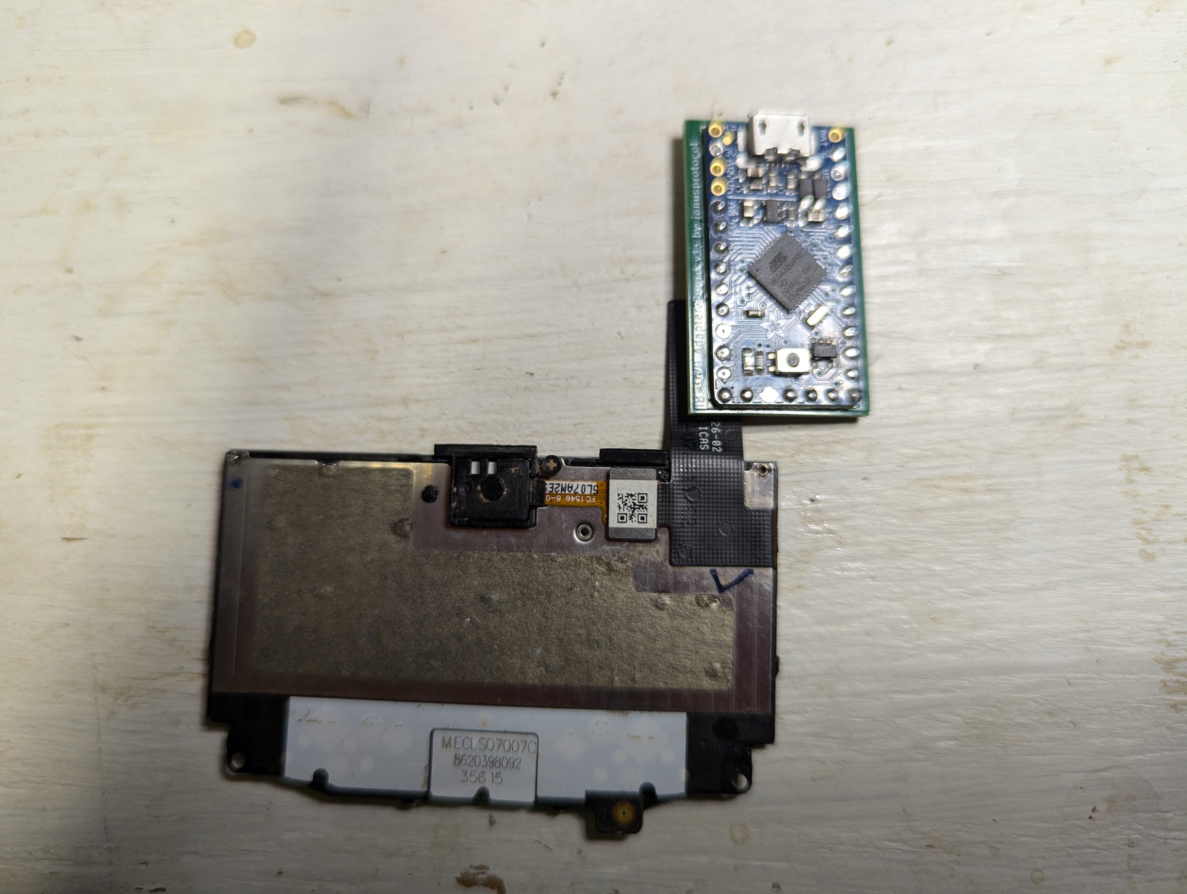
I hate smartphones. They're designed to be disposable, fragile, obtrusive, addictive, and penetrative. The modern ones are so obviously a surveillance device and a money grab I just hate having one on me. However, access to data for navigation and more common things like text and voice is somewhat necessary for the traveling I do. To both solve this social problem I'm experiencing and to improve my hardware and software skills I've decided I'm going to build a "fantasy console," aka a cyberdeck. However, I want mine to have cellular phone functionality if possible. The wishlist for the device:

1) all components need to be easy to obtain, work with, repair, and replace. Nothing proprietary.

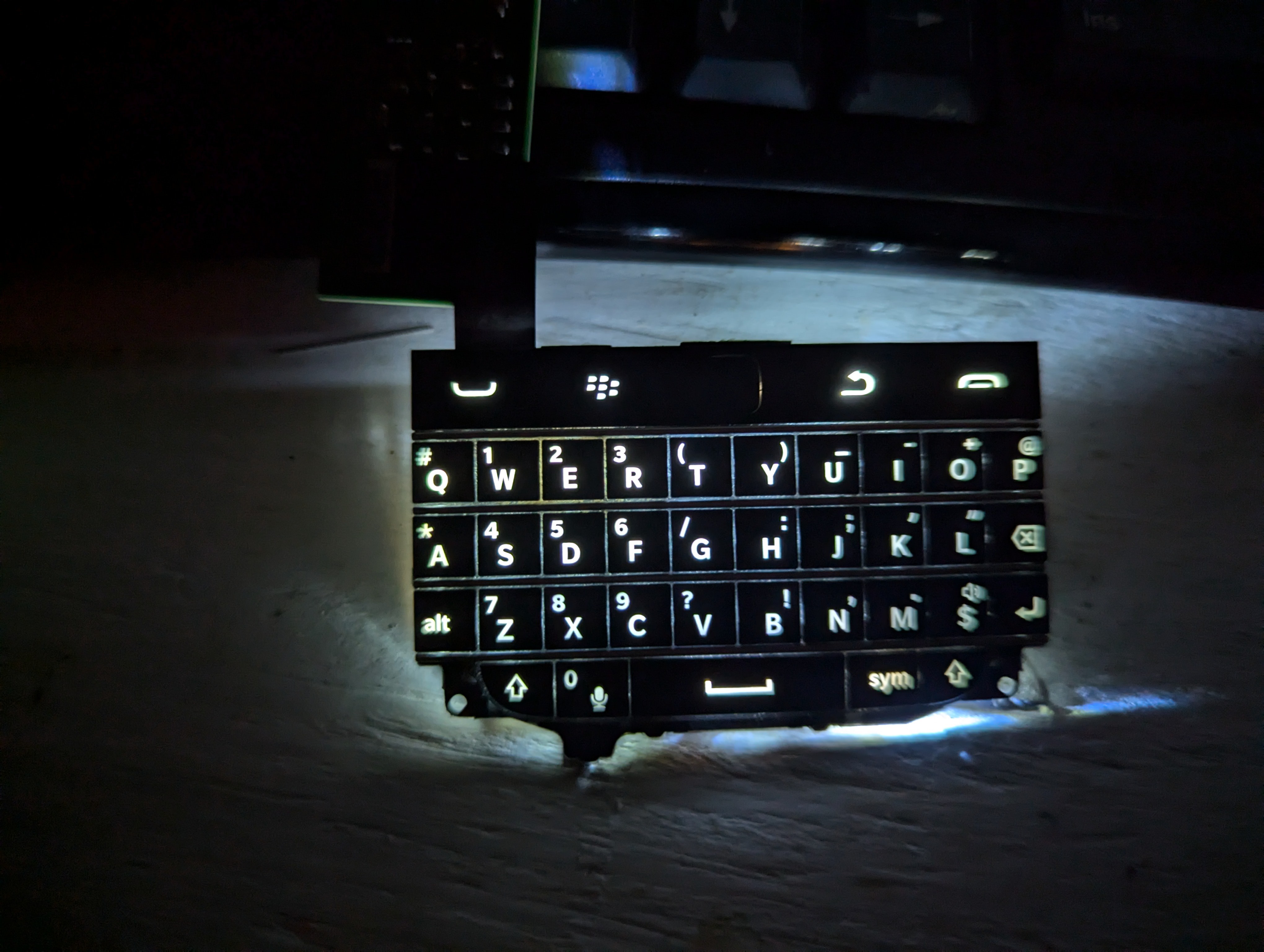
2) No touch screens, as their interface is power hungry and unnecessary most of the time.

3) Device should be complex enough to handle a Linux distro

4) Device will include some GPIO ports a la the Flipper Zero for add-ons

5) Physical switches capable of hard-cutting power on comm modules (LTE, WiFi, GPS, LoRA)

6) Optional: include LoRa capability on board

IB_Q20.zip

Contains KiCAD files for the ItsyBitsy 32U4 3.3V 8MHz to Q20 adapter PCB

Zip Archive - 196.41 kB - 09/08/2024 at 12:13

Download

Q20AdapterPCB.zip

Contains KiCAD files for Q20 Adapter PCB

Zip Archive - 21.87 kB - 07/21/2024 at 16:45

Download

View all 11 components

  • Prototype 3: Screens, Check

    janusprotocol10/03/2025 at 10:27 0 comments

    I got fed up trying to write a driver for random DSI LCD screens, as there is some sort of undocumented black magic in their construction. Instead, I looked for existing solutions, and I found some in the form of Waveshare screens. I bought the 4.3 in and 5 in versions, and I really like the 5 inch. It's just big enough to be highly versatile while still not so big as to affect the overall size of the device. I was able to just plug the damned thing into the CM4 IO board, download the RPi OS with the Waveshare drivers precompiled, and everything booted up with zero issues. 

    The topology of the 5" screen does come with some redesign considerations. First, the entire screen module is 8 mm thick. I'm shooting for a device no thicker than 25 mm, meaning that I'm looking at 2-4 mm more space for the screen and the remainder for the body of the device Second, the screen suggests designing a "sit in place" cyberdeck reminiscent of a tiny laptop. The benefit of this is a larger keyboard (good for my larger hands) with the downside being a more complex hinged design.

    There's a lot of dead space in the back of the Waveshare screen meant to bolt a RPi to it. The current plan I'm working up is to create a subboard that attaches to the screen which will hold a card containing the CM4 and the SSD. This should allow some flexibility in upgrading in the future, as this approach will allow me to design cheap 2-sided boards to interface with various CM models and the Outlander infrastructure. The breakout list is surprisingly short: USB, DSI, HDMI, I2C, a couple SPI and GPIO, 5V power, and a few misc. functional pins. The subboard itself will have a three port USB hub chip attached, thus even if there's only one USB port into the CM the system will be able to handle the interface with the SIM7600G, the RP2354, and the external data and power USB-C port. The radio modules (Si4735 and SIM7600G) may also fit on this subboard, which would make the most sense since when active the flipped up screen is the best option for antenna mounting.

    As for the casing, I'm planning on printing it in polycarbonate. While I haven't settled on a color for the case, I know I will be printing the keyboard keys in transparent PC with letters embossed in black PC CF. As I plan on including some NeoPixels onto the keyboard PCB, this should serve as great backlighting as well as some RGB flair.

    The last step before I move on all of this is getting the power subsystem finished. My initial design is hella expensive to manufacture, so I need to enlarge my vias and do some rearrangement of components to make the order acceptable in price. Once completed, I'll be able to start putting everything together into a functional prototype.

  • Prototype 2: Functional Si4735 All-Band Radio

    janusprotocol09/02/2025 at 11:49 0 comments

    My original prototype for the all-band radio module bombed, as I left the SENB pin floating. This was especially stupid, as SENB designates the I2C address for the chip (0 = 0x11, 1 = 0x63) so by leaving it floating the various fields and currents in the surrounding silicon could and did cause the address to fluctuate, making communication with the device impossible. Literally one millimeter away from the ground plane lay the SENB pad, and given the weird topology of the Si4735 there was no way I could use a botch wire to solve the problem, so the board was a total failure. 

    But, the fix was both easy and obvious, so I attached SENB to ground like I should have in the first place in KiCAD and ordered the boards from JLCPCB. I soldered everything together, attached the board to a Pico 2 W, and the chip showed up on the i2c scanning sketch I loaded at 0x11. I also found an Arduino library and corresponding example files that provide rudimentary control over the radio's functionality, but unfortunately while the radio was talking to the Pico, it wasn't able to tune to anything. After some digging, I found a short checklist of things to check when the radio isn't starting up properly. As I was walking down this checklist I discovered that the crystal's load capacitors should be 22 pF each, while I had 100 nF caps installed. That's 4600x more capacitance than intended, so why did I do that? Well, 1) I don't have any 22 pF SMD caps, so I guess I just subbed them in for some reason? Frankly can't remember making any of these decisions but that's what I get for not keeping good notes. In any event, I soldered some 22 pF THT caps onto the pads, and this worked quite well. The radio started up immediately in FM mode and tuned to the default, complete with an analog audio stream. Awesome, I finally got something to work again! 

    The radio was able to do FM quite well with the antenna I chose for it, but the AM antenna idea needs work along with the shortwave circuit. However, the purpose of this board was to provide a platform for minimal functionality, and this is that minimum functionality so I'll take my dopamine hit please and thank you! With this and the keyboard prototypes complete, and the screen issue being solved by relying on Waveshare, all that's left is to produce the power system using a 2S cell.

  • Learning By Doing: One Year Later

    janusprotocol08/19/2025 at 00:58 0 comments

    In the summer of 2024, I developed an insatiable drive to do and experience new things. I was just bored mostly, as my dayjob as a life scientist had turned away from what I love, which is the actual doing of biology and bioengineering, and more towards mentoring, writing, meeting-sitting, and computer touching. So, I wanted to pursue making and doing things again in my spare time. Having always had a knack for tech and electronics, the first project I settled on was "make my own cell phone." Exactly the kind of project to get me locked in HARD; something I already know about so there are easy "toeholds" in the knowledge base were I can begin, impressive sounding, technically feasible but non-trivial, and has that certain je ne sais quoi. So the work began...

    A year later and I can definitely say that I've made a lot of progress towards getting there, though I'm moving at a slower rate than initially anticipated. Part of that is the state of the world: after my last update in March I sunk into a bit of a depression that didn't really lift until maybe the beginning of this month, and I made little progress. Part of that depression was also from 3 out of 4 submodule boards completely bombing with nothing working at all on them, as it felt terrible to put together a prototype and you cant even get fucking current coming out of it. Still, I have a short list of things I can do now that I couldn't do a year ago:

    -built a functioning 2 m transceiver for the Flipper Zero
    -built a functioning keyboard prototype for the Outlander with the RP2350, complete with software
    -learned enough C, CircuitPython, and MicroPython to write simple programs and modify existing codebase
    -use, modify, repair, and maintain FDM 3D printers
    -design multipart structures using FreeCAD for 3D printing

    While I had initially hoped to have an in-hand prototype by beginning of 2026, that's looking less and less likely. Unfortunately after designing the keyboard I realized I hated how small it was. It was also causing design constraint, and I despise those tiny Hirose connectors. I also have all but given up on using DSI screens out of the box, so if I get a DSI bridge all-in-one unit that should just solve all these problems. If I can get the screen solved and a prototype keyboard made, I should be halfway there to the device. I also decided to change the interface with the CM4 module to make the Outlander compatible with other CM-like devices. Instead of plugging directly into the Outlander mainboard, the CM will plug into a card, which will allow for peripherial devices specific to that certain CM to be added to the other side of the card. For instance, the RPi CM4 only has one USB2 port (LAAAAME!) but the Outlander needs three (one "out" of the device, one to the 4G/LTE module {because why would you have an LTE modem running at 4 Mbps?}, and one to the RP2354 driving the GPIO and the keyboard; for its card, I'll add a 3 port USB chip to the back along with the SSD to save space.

    While saying I look forward to the coming year is 100% incorrect, I do hope I can keep this momentum. This hobby has become a very welcome distraction with the state of the world, and I'm fortunate to be able to engage in it as I do. 

  • Prototype 1: Keyboard and trackpad success!

    janusprotocol03/20/2025 at 18:31 0 comments

    After eight months of working on this project in my "spare" time, I've finally got something checked off my list: I got the keyboard module completed! Well, nearly completed, but I know what the problem is.


    Rather than redesigning a new board to try out is RP2350B based WeAct Studio module, I decided to use some of my training from the 1990s and acquired some prototyping circuit boards, or protoboards. I realized I could just solder some wires to the delicate pads on the boards I already designed, then solder those down to the protoboard and connect everything with wires underneath. The bigger protoboard also provided a nice surface to tape down the Q20 keyboard, which prevents it from coming loose from the Hirose connector; those things aren't meant to bear any sort of load, after all. Finally, this is my first time building with an RP2350 chip, and wow is it cheating! You can just stick any old IO to any old pin on that thing with very few limitations and you can expect it to do what you need. An incredible piece of technology and one that is sorely underused IMO.

    In any event, once I got the RP2350B board all connected to my adapter board and fired it up, I was able to kludge together code to emulate a keyboard and mouse using CircuitPython. The keyboard was fairly straight forward, but now that I was able to confirm the functionality of a keyboard with a reliable setup I could tell that there's only six columns in the keyboard, with the seventh being reserved solely for the End Call button in the topmost right corner. That switch just connects the Column 7 input with ground, which means to use the End Call button I told that pin to act as a pull-up input. This seems to have worked absolutely fine with no circuit modifications, another big plus to the RP2350.

    I was really worried about the trackpad because I Do. NOT. KNOW. What I am doing. I realized that the trackpad was communicating with the MCU using a logic-level shifted I2C connection, and slowly over months I figured out what that actually meant in terms of using it as a protocol (the bus, pull up resistors, etc.). I dug around and found other software for devices making use of the Q20 keyboard and trackpad, which led me to realize that this trackpad sensor was writing data like binary motion detection and motion in the X and Y axes as value in various registers, which can be read out by the MCU via I2C. I rigged up a script to read a bunch of these registers, and confirmed my speculation. My jank code scans the trackpad register tied to motion detection, and if it detects motion it reads those X and Y registers it moves the mouse cursor according to the intensity of the movement detected.

    So what's the problem? I can't get the full keyboard to work because when I soldered the adapter board down I must've popped a weak solder joint on the ROW5 pad, which obviously means there's no way to get a signal through on that pin. I tried to do some jank resolder and botch wire patching but to no avail. Oh well, that's prototyping for you. So it works! But....I kinda hate the Q20 keyboard. The trackpad sensor is great, but my fingers really appreciate a bit more button room. So, I may try to just make my own keyboard directly on the PCB with some tactile switches under buttons. If you know of any good online resources for making keypads on handheld devices in this way, please send those resources my way! 

    The things that still need testing are the power system, the LCD system (I'm not going through HDMI FFS), and the radio system. My plan is to spool up these prototypes and have them ordered by the end of the month.

  • Hey Bro I Just Need One More Design Log And I'll Be Good Just One More Bro

    janusprotocol02/15/2025 at 06:01 0 comments

    I know I said I was done designing but I had a realization.

    First, why am I obsessed with getting this damned ATMega32U4 to do what I want when I got the keyboard to work on an RP2040? Also, the 2040 has a ton of features that could be cool. Also also the RP2350 was just released this year and it has even more features than the 2040.

    What I realized is that I could use the B version of the 2350 which has 48 GPIO pins exposed to drive my keyboard/trackpad combo. The pins leftover from connecting the Q20 keyboard will be routed to a 20 pin connector on the side of the Outlander for module connection. While it makes using the pins a bit more complex, the RP2350 also has three Programmable IO (PIO) blocks that each contain four state machines. These PIOs basically act as limited FGPAs that are specialized for communication protocols. I've seen demonstrations of people, say, programming VGA output using PIO, which is cool. Hypothetically you could program one of the 2350 cores to drive the keyboard and use the other to emulate some ancient decrepit protocol through a port last used widely 20 years before you were born. That, my friends, is cyberpunk as fuck.

    As I was starting to get prototypes built I realized that the Raspberry Pi CM4 only has one USB port?! That upends my plans, as I wanted one device-wide port, one port for the cellular/GPS module, and one port for the keyboard/trackpad module. Fortunately, I found a solution on AliExpress: Waveshare makes a SIMCOM 7600G-H board that has the same form factor as the Pi Zero that also doubles as a USB hub. So, I'll connect the single USB port to the Waveshare modem, then the exterior port and the keyboard module to the waveshare.

    Finally, I called uncle on directly using DSI to drive an LCD. Writing drivers is hard and is going to take longer than I thought to learn, so in the meantime I decided to order an HDMI to LCD board that's compatible with the 720x720 board I already have. This will preclude fucking about with DSI drivers and just give me something to work on while I slowly learn C.

    Weirdly I'm doing better learning CAD than how to do the electronics, and I already have a prototype "case and screen" design. The LCD and keyboard are both taped into their slots, so it's far from functional. However, I'm very pleased that what I'm making will look very close to the idea I have in my head. Exciting!

  • Design 11

    janusprotocol12/30/2024 at 01:03 0 comments

    I took the Christmas vacation to do some finalization of design on this project so I can begin prototyping. I decided that the CM4 module plan was a very good idea, so it's in and the Zero 2W is out. I found a pretty cool multiband receiver IC in the Skyworks Si4735, and I decided on a telescoping antenna to give it that mid-80s hacker vibe we all love. I'm definitely including a LoRa transceiver because I really feel like it has potential to be awesome, and it takes up very little power and volume.

    Because the CM4 I ordered also included a dev board, I've actually got almost everything ready to go in a non-portable form so I can start testing these systems. Thus, this is my last Design entry for quite a while, as I'll be moving into the prototyping and development phase. I already have a short list of things I need to test: write and deploy keyboard/TP firmware to the ATmega32U4, get LCD working, get both radios working, buy a 4G/LTE data SIM and get cellular data and positioning working, get the camera working, and test that the power system I've designed isn't going to catch on fire.

    Finally, I decided on changing the name, as the "___Berry" name scheme isn't that clever and isn't really descriptive of what I'm trying to make. I've come to realize that what I'm building is called a "fantasy console," also known as a cyberdeck. What I've designed is a multi-comms device for someone with interests in radio and hardware interaction that I can also use as an everyday consumer device, which is, yep, a cyberdeck. A nerdphone for nerds, if you will. Thus, the project will be known henceforth as the Outlander Cyberdeck. Why "outlander?" One of the best uses of radio is connecting people off of and outside existing comm infrastructure, like those who wander. Also it sounds cool.

  • Design #10: Side Projects and Revamps

    janusprotocol10/13/2024 at 01:37 1 comment

    After playing with an LCD screen for weeks, I realize that my lack of C++ experience is really hindering any sort of advancement in this sphere. It's a much lower level language than Python, which is the only computer language I speak. I'm limited limited by this shortcoming, so I've decided to whip up a side project or two with the explicit with the goal of learning how to speak C++ while simultaneously doing something cool. I'll be designing a module for the Flipper Zero I'm calling the Squeaker, an amateur radio GPIO add-on that will allow for monitoring and, hopefully, transmitting of the two-meter and 70-centimeter amateur radio bands.

    On the actual project side, I've decided to move away from the original Zero 2W form factor boards that inspired this project to the beefier Compute Module 4 (CM4) form factor boards, specifically the Orange PI CM4 module. Instead of worrying about which pins have been exposed, how they're exposed, removing unnecessary USB ports, etc that I'd have to content with, I can design a motherboard that the CM4 will plug into, thus I can route whatever I want wherever I want without issue. As I've already figured out how to deal with Hirose B2B connectors during the Keyboard Project, I'm certain I can get these adapters figured out. Another benefit of using the CM4 is that it can directly drive LCDs via a 2-lane and a 4-lane MIPI DSI channel, thus simplifying the end system; just wire a connector so that it jives with the LCD and you're good! Much simpler, as displays are one of the few unstandardized modern parts I've run into. I dunno what that's about but it definitely sucks to find out that these displays you bought are not very cross-compatible!

    The HB1 is looking like it will contain the following: a display, the Q20 keyboard and associated subprocessor, the SIM7600G-H to provide 4G/LTE and GPS, a GPIO header similar to the Flipper Zero but with better port selection, some general purpose well rounded camera sensor, and maybe a couple of radio receivers/transceivers, depending on how much space I have in the case. I'll begin sketching up what that looks like once the OPi CM4 arrives and I get some  boards made to test an exploded version of my design.

  • Design 9: Success!

    janusprotocol09/24/2024 at 22:00 0 comments

    After weeks of work I f

    Well piss, here I thought I would be clever and write an intro ON the working keyboard, but it seems I must've torn a connector or something, as a whole collection of letters I mapped just last night are no longer sending signals to the MCU. Oh well, I'm just thrilled that I now have a keymap that I know works and the confidence that I can actually engineer circuits.

    Rewind to Friday: I've been on-and-off trying different ways to get QMK firmware onto the IB 32U4 8 MHz 3.3 V board, to no avail. I thought I was getting somewhere using AVRDUDESS, but when I tried to move the window over it crashed and bricked the chip. Arduino IDE cannot write to it anymore, so I may have borked the bootloader. I'll have to investigate repairing it one day, though I doubt it's usefulness as the backpack is soldered on tight. I recently discovered that the lead-free solder I have has a pretty high melting temp, so that backpack board I designed is on there tight.

    In any event, I was at a loss as to what to do. I tried to wire up an ATMega34U4 I had on an adapter board, but that didn't seem to get me anywhere. I thought about just calling it quits when I realized that I had four brand new Raspberry Pi Pico 2 boards I had impulse bought when I heard how scarce they were becoming, and I mean $5 a piece is like laughable for this hobby. Anyway, as I read into them, I had somehow missed the fact that you can program them in Python?! Why was I fucking around with C++ this whole time when I could've been coding in a language I already spoke? Gah!

    I heated up the soldering iron, cut some lengths of wire, and soldered up this rats nest:

    It's ugly and mildly embarassing, but after I installed KMK firmware on it, I was able to make a seven pin column, seven pin row layout, then observe the firmware output as I pressed each key. Voila, a Blackberry Q20 Keyboard that can type until I break it! I still need to figure out the trackpad controls in KMK, mostly if it's possible at my technical skill level. Still, I did it. I made a keyboard, hurray!

    I still have another couple parts to test, but then it'll be time to draw up a motherboard that will combine all these disparate pieces of tech into an actual device. Unfortunately, life gets in the way: my wife and I very much want to move, so here sooner than later I'll have to tear down my bench to do wall work, then possibly again to move after said wall work. While it would be cool to have a functional device by the end of the year, I'm in no rush. Besides, a new house means a better workshop most likely!

  • Design 8: Easy Hack Oven

    janusprotocol09/14/2024 at 12:54 0 comments

    While I waited for PCBWay to produce my boards and the accompanying stencil, I contemplated how I was gonna put this board together. I ordered a smaller, more controllable hot air gun, but as I got it from AliExpress it's unknown when things will arrive. I had read stories online about people hacking a toaster oven (AKA making an Easy Hack Oven) to act as a reflow oven, which was intriguing. After researching desired characteristics and what was available locally, I found a Black & Decker quartz element oven with power rating > 1000 W and reasonable price at Kroger, and I purchased a Walmart oven thermometer with probe. While my first thoughts were to go full send on hacking this thing, but as I thought more and more it seemed like I could just...watch the oven and control it manually for these IB backpack boards. So, I taped the probe to the oven tray, did some empty tests to get ramp rates and temp overshoot characteristics, and tested my planned procedure with solder paste only on the board.


    That went well, so I applied paste with the stencil, placed components, and ran the reflow procedure. I did place kaptom tape on some of the in-pad vias, as I wasn't paying hundreds of dollars for PCBWay to fill them with resin. The hope for this was the tape would keep any molten solder from the pad from running out from under the board, which is why people fill vias in the first place when they're in pads. Anyway, during reflow I cut the oven power at 110 C, which cruised slowly over a minute or two to 155 C or so, then pulled the tray out an applied cool air via a handheld fan until the temperature dropped to 120 C. At that point I removed the board from the tray and placed it on my helping hands platform to rapidly cool. 

    The only flaws noticed were the C3 capacitor falling off almost immediately, R5 was comically skewed off of one of its pads, and the Hirose connector had a single solder bridge across pins 4 and 5. I resoldered C3 and R5, then resolved the bridge with some flux and a poke from my soldering iron. While I don't have any firmware ready to drive the keyboard, I can easily program the board via Arduino IDE to control the brightness of the backlight via PWM output from the IB 32U4 Pin 5. It looks SO much better than my initial test, which is super encouraging.


    I guess now I need to buckle down and figure out if I can use QMK or some other existing keyboard firmware package to drive the keyboard or write my own. I'm closer to the end of this phase of the project than the beginning, and once complete I have to test some display in a similar manner. I'll probably start designing the motherboard for the HB1 at that point as well, since my experience with the IB 324U really demonstrated the power of these prefabbed boards to expedite prototyping.

  • Design 7: Limited Success

    janusprotocol09/08/2024 at 12:13 0 comments

    After winging about delays last week, I made some leaps and bounds!

    As mentioned last week, I impulse purchased an ItsyBitsy 324U 3.3V 8MHz board from Adafruit (here) because part of my problem prototyping anything that needs a bunch of auxillary devices, like oscillators and diodes, suddenly becomes a nightmare to quickly slap together. Thus, with all of that nonsense taken care of, I was able to rapidly type out a short proof of concept Arduino sketch that would behave something akin to a keyboard. I was able to print the letters Q and G to screen on my workbench Linux by connecting a COL output to a ROW input, much in the same way as what would happen with a keyboard, and it worked! I'll at least be able to get something moving on this module.


    But how am I gonna get a keyboard attached to this thing, let alone the BBQ20 with its special squirrel adapter? I decided to bite the bullet and design a new adapter board using some of the circuitry from this handheld keboard module as source material. Since I figured it'd take me much longer to figure out the keyboard firmware than this hardware, I decided the smart thing would be to make this adapter board into a board for the ItsyBitsy (hereafter IB) in order to use the existing hardware to make life easy.

    I've uploaded the KiCad files for this adapter board, feel free to use them as you see fit.

View all 16 project logs

Enjoy this project?

Share

Discussions

Cyril Hrubis wrote 09/02/2025 at 20:33 point

The hardest part of this project is going to be the software. I've been writing a graphics stack that includes widget library for devices like this for a decade and I'm still at a beta phase at best.

I also have userspace drivers for SPI displays I find them easier to work with than DSI and for small displays SPI is fast enough. SPI display with ST7789 and 320x480 resolution can be clocked fast enough to play video and the driver looks like this https://github.com/gfxprim/gfxprim/blob/master/libs/backends/linux/gp_display_st77xx.c

  Are you sure? yes | no

Robert Gawron wrote 09/14/2025 at 16:36 point

There is already an opens source library for embedded graphic stack, you can take a look (it's for monochrome displays):


https://github.com/olikraus/u8g2/wiki/muimanual

  Are you sure? yes | no

Cyril Hrubis wrote 09/14/2025 at 18:28 point

That library is for a completely different target though. What I'm writing is a graphics library for a Linux with minimal compositor/window manager that runs on small displays, so that you can run terminal, play video etc. on RPi on these displays. That's a bit more complex project than widgets for arduino.

  Are you sure? yes | no

Similar Projects

Does this project spark your interest?

Become a member to follow this project and never miss any updates