Supplies
Here's a list of components needed (you can also ship from Aliexpress):
- ESP32 DEVKIT V1 board
- Nova SDS011 PM10/2.5 sensor
- DC/DC step-up converter
- MHZ-19 CO2 sensor
- DHT11 Temperature and humidity sensor
- 3V7 1000 mAh LiPo battery
And some utilities:
- 3D printer (and slicer software)
- Arduino IDE (1.8.19)
- Laser cut (you can also use a printer)
Step 1: Case Development
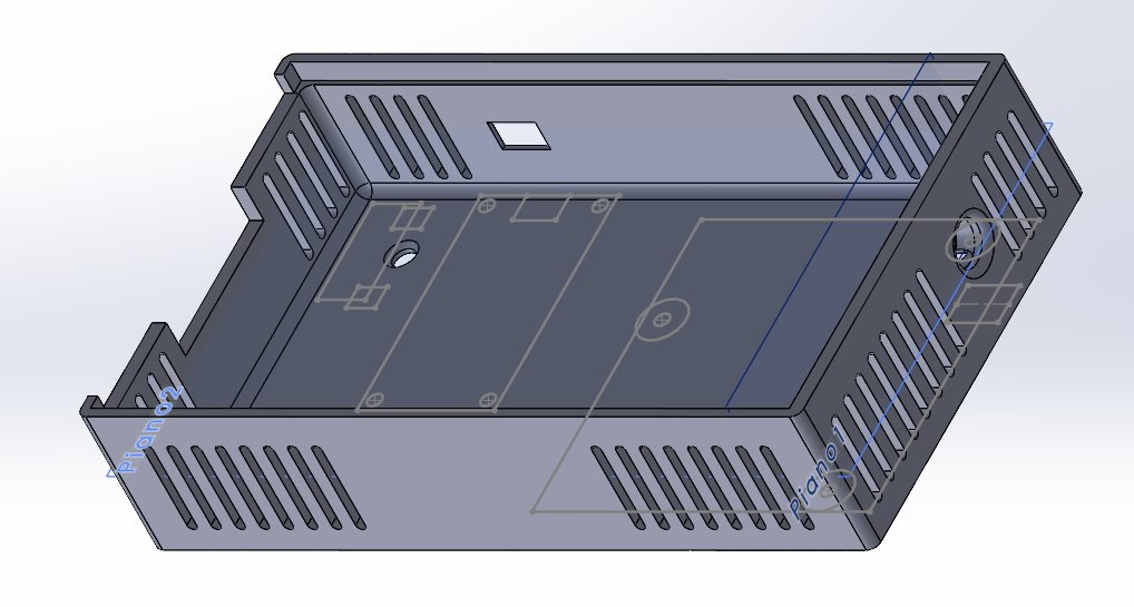
We began designing the housing for the PCB using a 3D CAD program, paying close attention to the height of the air inlet and outlet of the SDS011. The sensor uses a 5V fan, so we utilized the outlet air to cool the electronics on the right side. Additionally, we designed openings on the right side to keep the MCU and boost converter cool.
Step 2: Schematics and PCB
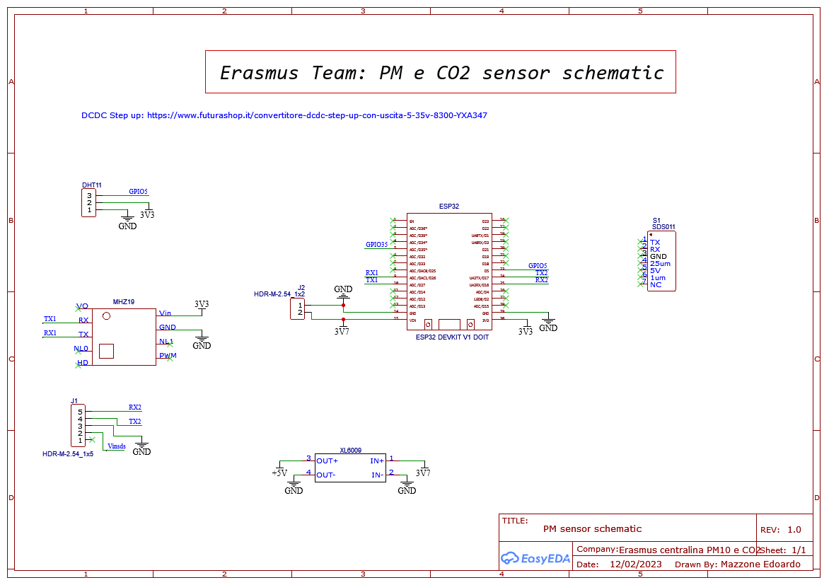
I began this project using jumper wires, but as the number of sensors increased, it became essential (for the sake of sanity) to design a custom PCB. I chose EasyEDA as software and started with the schematics.
As a PM sensor I've chosen the Nova SDS011 with UART protocol, I connected the sensor to TX2/RX2 of ESP32 through a jack (I use footprint for dimension for this reason isn't connected). The only difficulty is that it needs 5V so we've added a boost converter (XL6009) to step up the 3,3V of the MCU.
We've chosen DHT11 because we didn't need high precision on temperature and it's the most cost-effective one, finally, there's the CO2 sensor (MHZ19) connected to UART1.
Then there's a battery connection called "J2" on the scheme that powers up everything, consider that, in normal cases, you also need a battery management system like TP4056 we chose to omit it because this is a starting project and we monitor the sensor during the measurement.
So I started the PCB design trying to minimize the space occupied, we opted for a rectangular box so the board had to fit it, moreover, the SDS011 air inlet was on the left and we placed the battery above the sensor, MCU and boost converter were in the left part of the case so we leave some opening, now I think they could be reduced a bit.
Check the project repository for Gerber file needed to order the PCB.
Step 3: Assembly & Connection
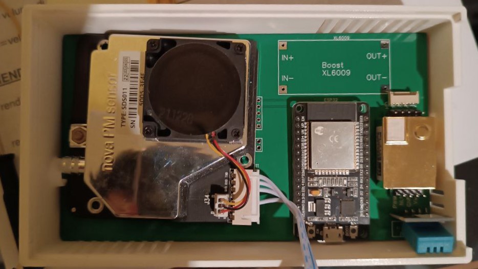
After the PCB was completed, assembling the device was the easiest part. We only needed to connect the sensors to the electronic board. First, we soldered a female header for the ESP32 to simplify replacement. Next, we soldered the MHZ-19, DHT11, and the boost converter. Then, we aligned the SDS011 inlet with the round hole on the left side of the case and connected its cable to "J1" according to the schematic. Finally, we connected the battery to "J2" (being careful with the polarity) and closed the case with a 4mm laser-cut wood cover.
Step 4: Code Drafting
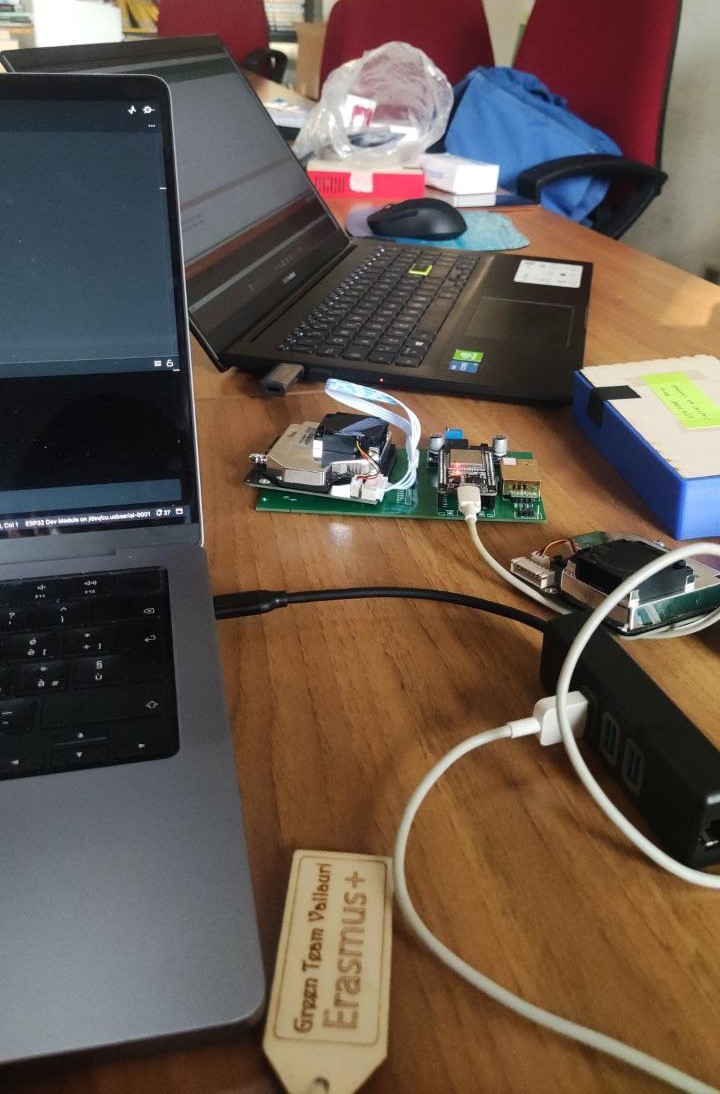
First, I installed the ESP32 add-on for Arduino IDE. We also needed some libraries to retrieve data from the sensors:
For each one click on <code> and then "Download ZIP", then in Arduino IDE: Sketch/Include library/Add .zip file and select the file downloaded.
The developed code includes a setup where the sensors are initialized, and in the loop, data are acquired and sent to the InfluxDB database.
void loop() {
  //Print not sended data
  File file2 = SPIFFS.open("/PM sensor.txt");
  if (!file2) {
    Serial.println("Failed to open file for reading");
    return;
  }
  Serial.println("File Content:");
  while (file2.available()) {
    Serial.write(file2.read());
  }
  file2.close();
If WiFi isn't available, the MCU stores data in SPIFFS as a .txt file, we chose this system cause we didn't think of a backup system when designing the PCB, now I reckon the best solution is a micro-SD card in combination with a dedicated struct for redundancy. The content of the file is the first thing displayed in the loop as you can see above, in this case, we simply print it in the Serial Monitor, you can also resend data...
Read more » Edoardo
 Jeremy
 mihai.cuciuc
 Radu Motisan