Arnov Sharma
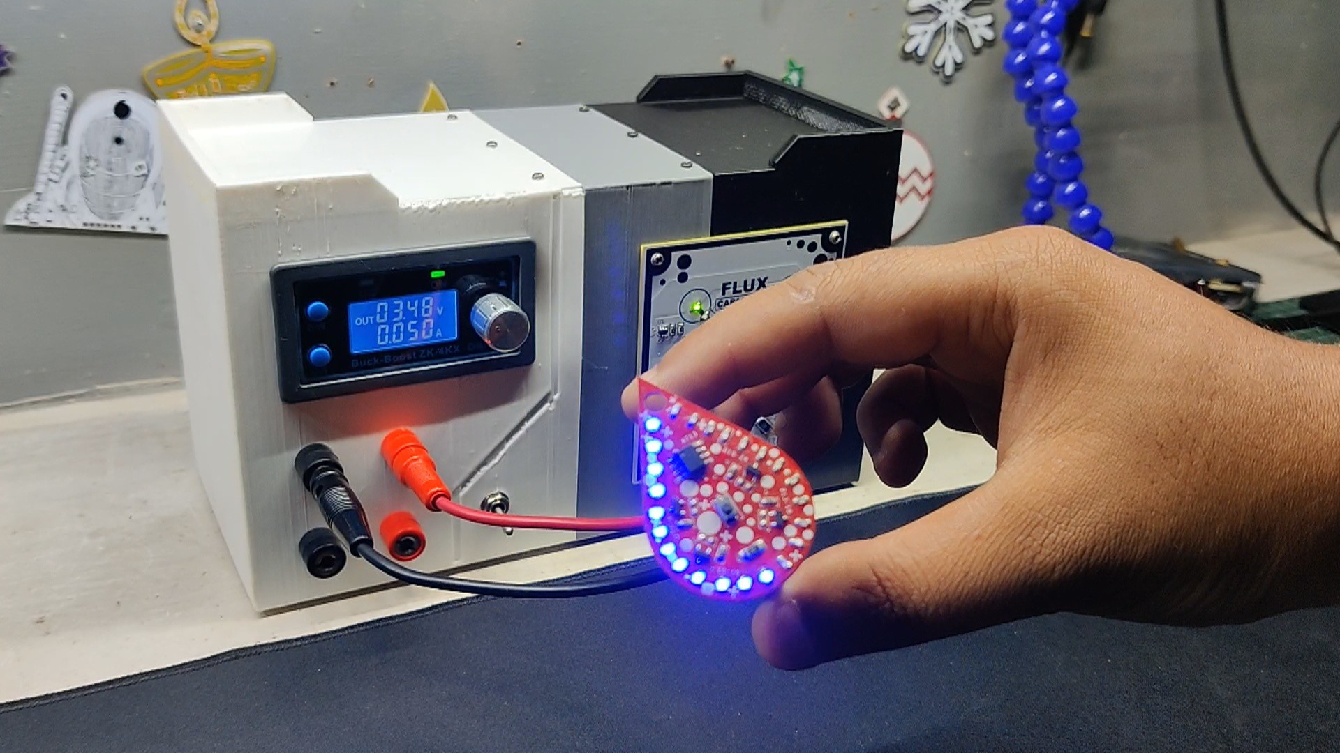
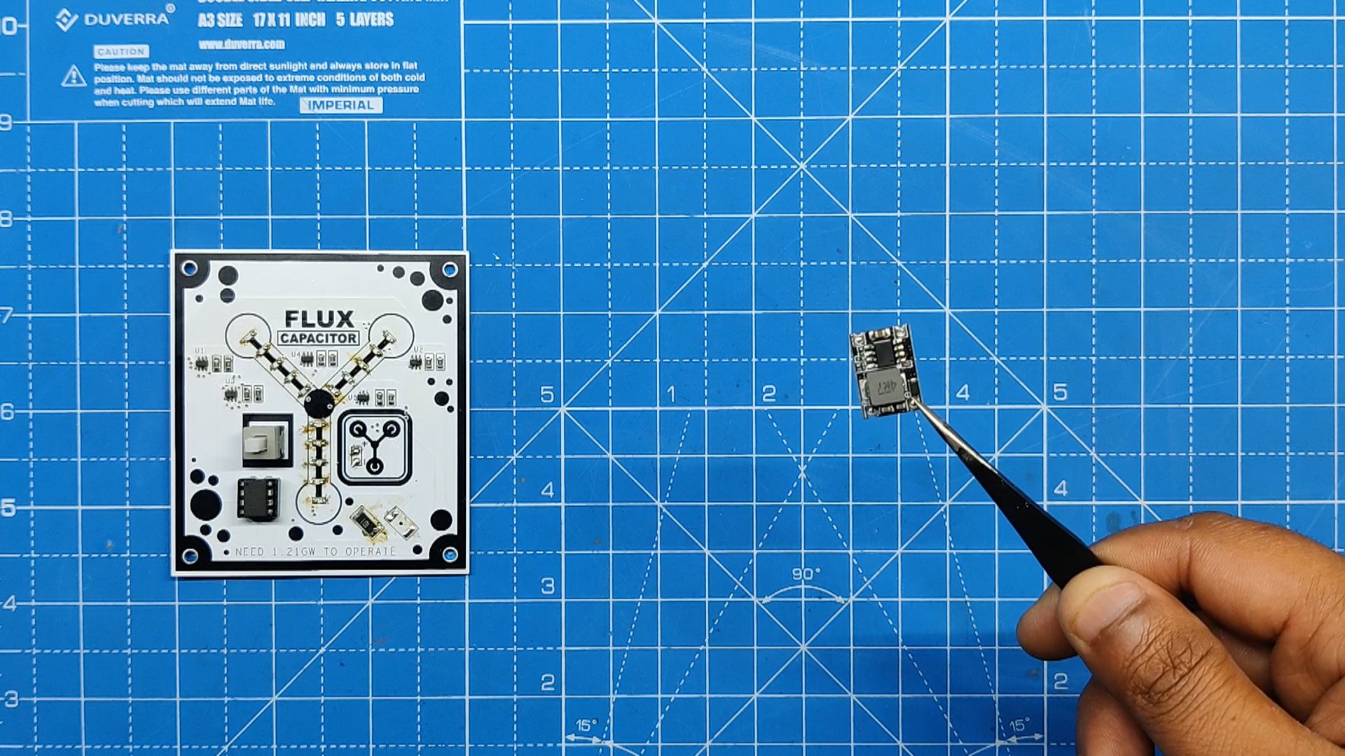
Here, we are using the ZK-4KX DC-DC Buck Boost converter module, an adjustable regulated power supply module with a voltage range of 0.5–30V and 4A. It can be used for a number of power-related applications, such as solar battery charging, as a boost converter to drive high-power LEDs, or even to create a bench power supply.
The ZK-4X is solely a module that requires 0 to 30V to provide us with regulated or boosted voltage and current; therefore, we needed to add a power supply, which we were able to recover from the Ender 3 3D printer. This power supply was a 24V, 10A SMPS.
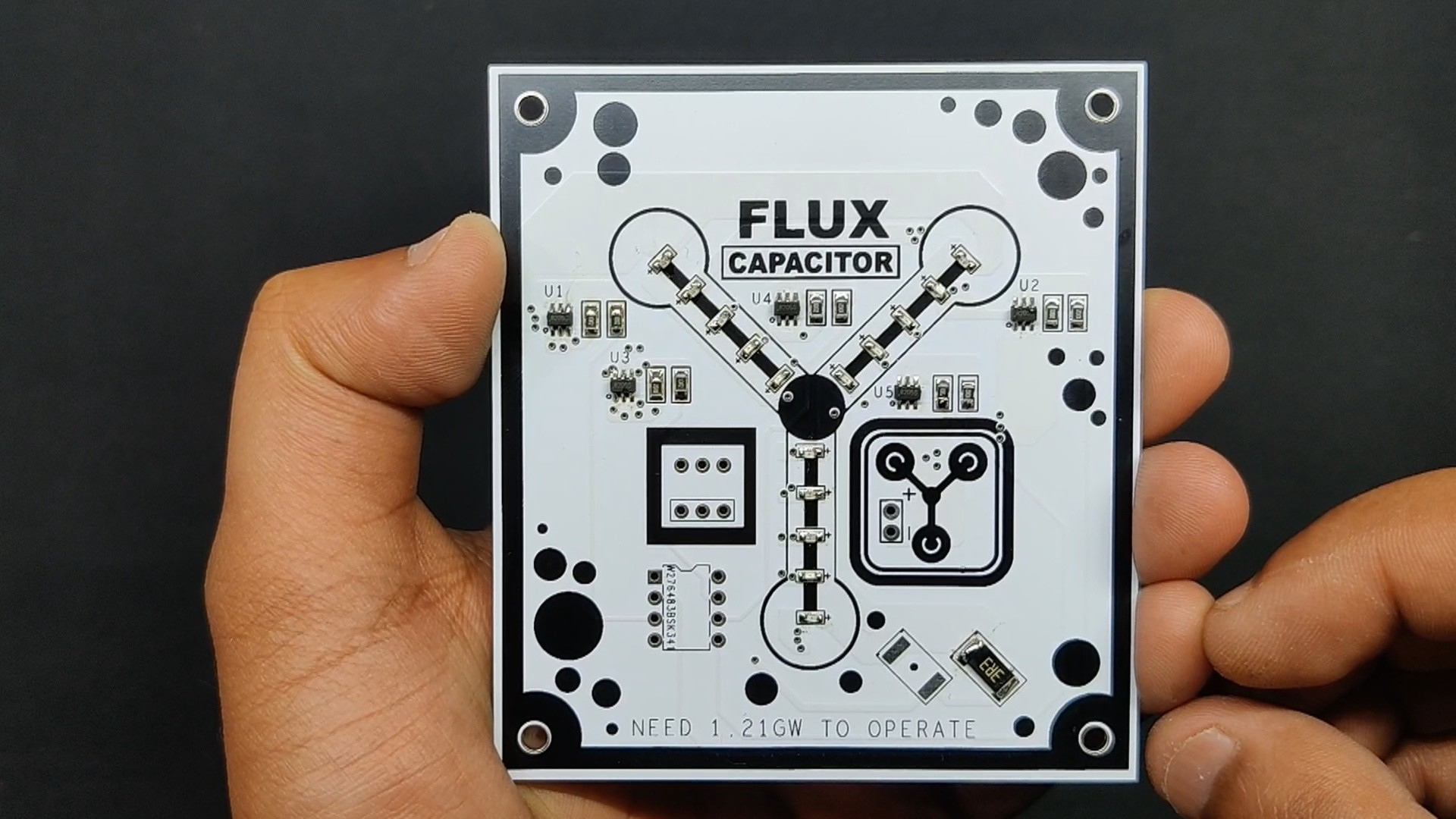
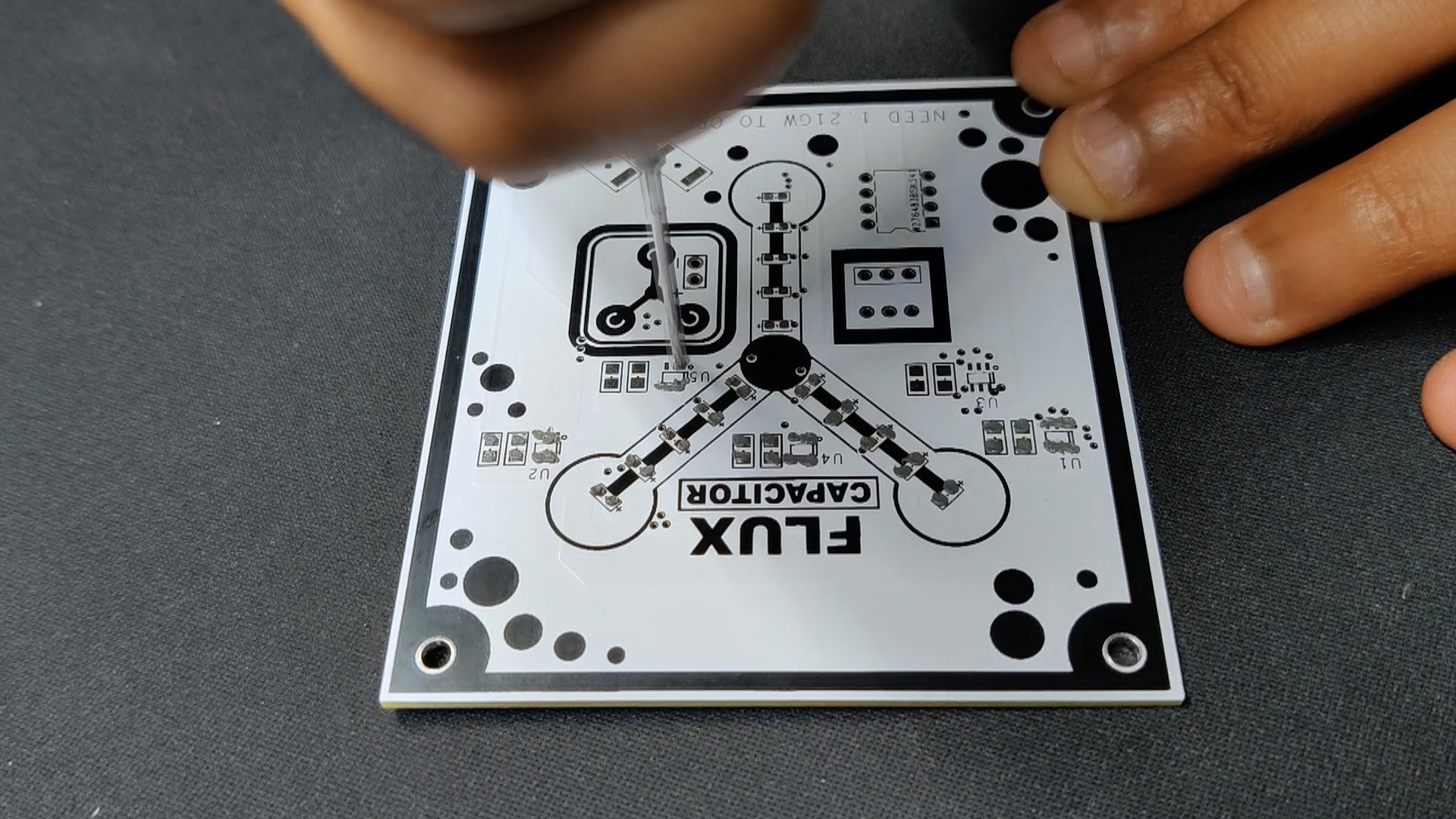
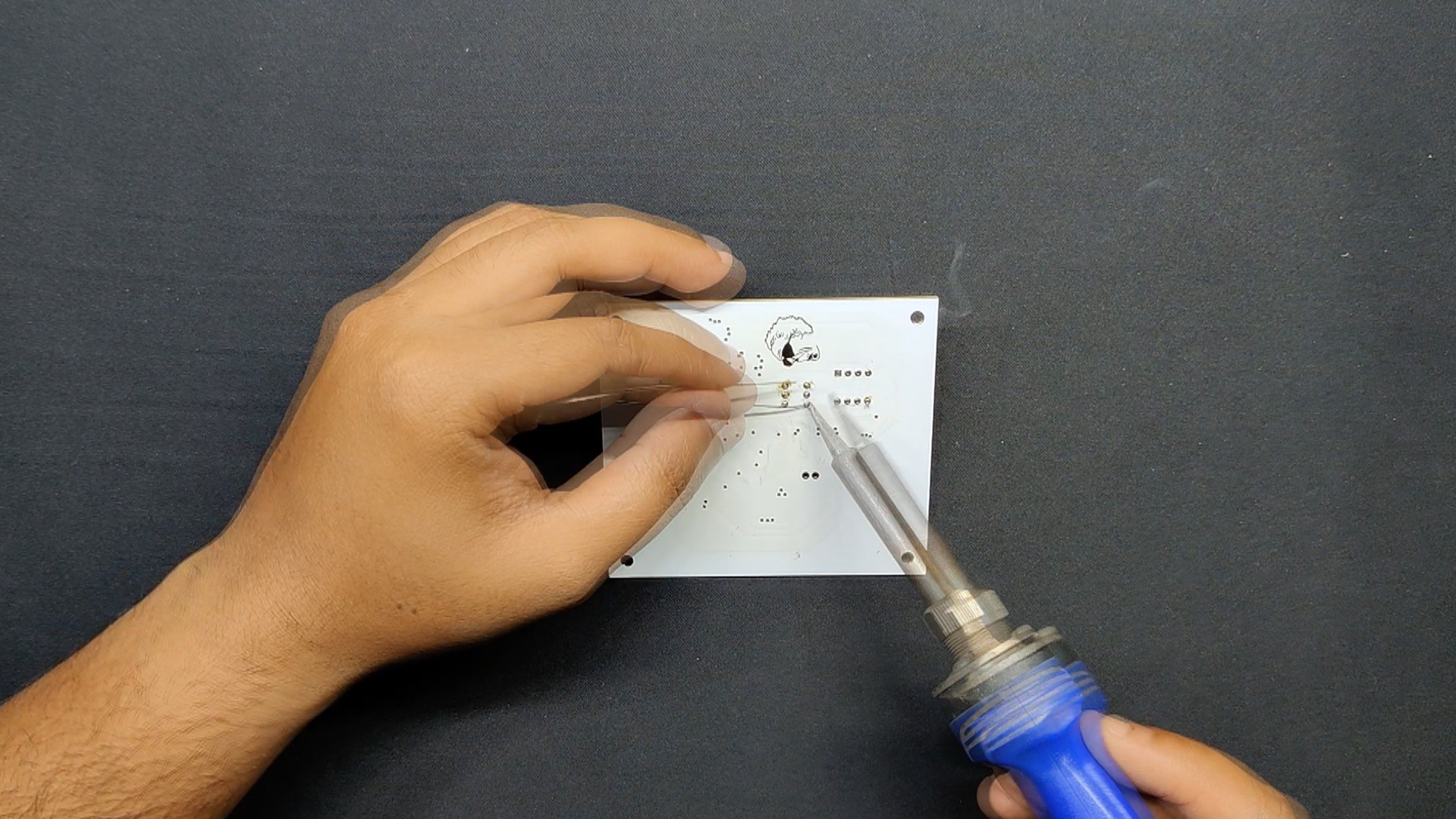
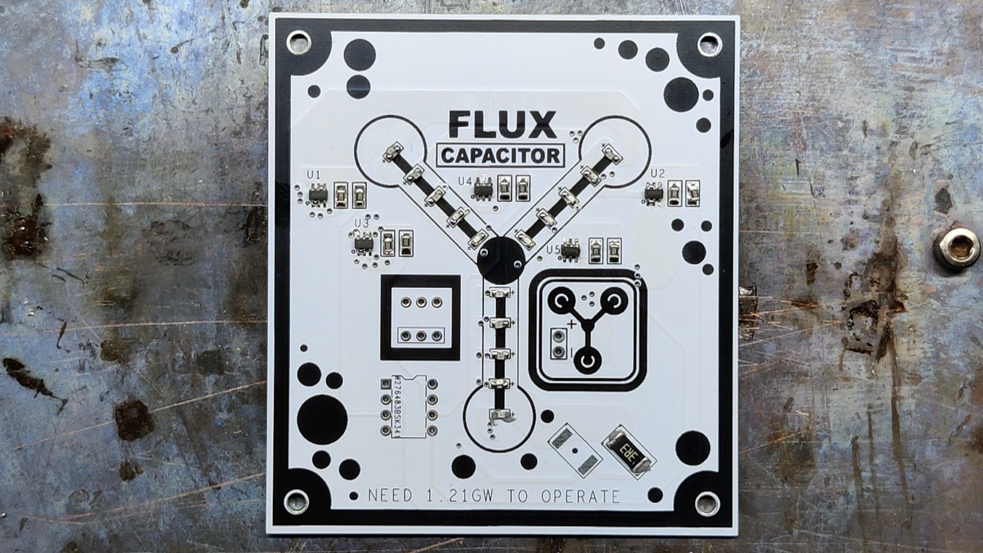
We created a PCB with a Flux Capacitor design to add some visual elements to our project. It has a few SMD LEDs that continuously display an animation like a flux capacitor. The Attiny85 microcontroller drives all of the LEDs, and the SMPS 24V power supply powers this PCB.
We added a Power INLET box with fuse holder, along with a few banana pin connectors and other stuff, which are all clearly explained in this article, so let's get started with the build.
ZK-4KX DC-DC Buck Boost Module
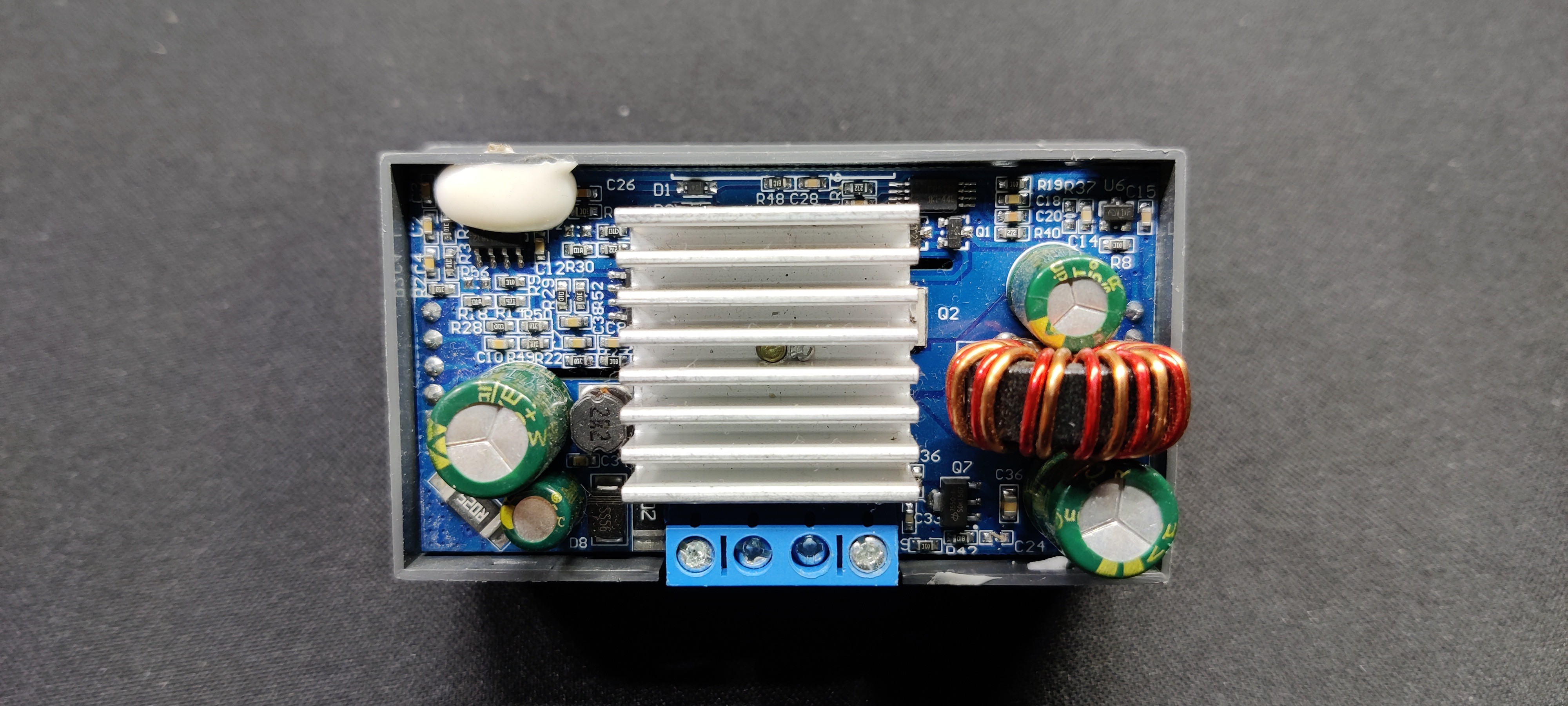
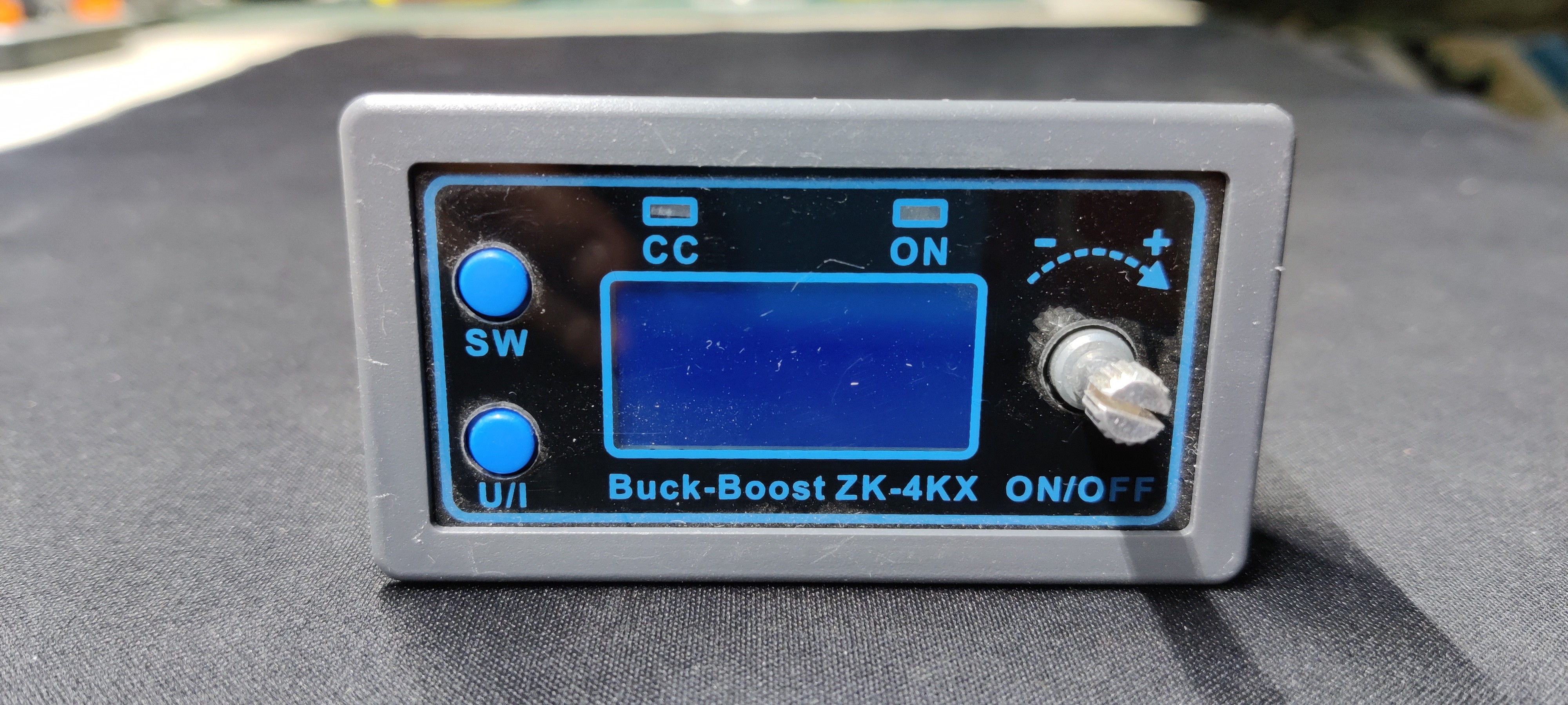
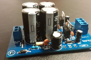
The heart of this project is the ZK-4KX DC DC Buck Boost Converter, which is a 0.5–30V 4A Power Module Adjustable Regulated Power Supply featuring an LCD that can display input/output voltage, output current, output power, output capacity/output time, along with many key features like a good conversion efficiency of 88%, stable 3A output current, input and output reverse protection, and more.
Here's its full manual, which you can checkout for more details.
https://manuals.plus/parts-express/zk-4kx-cnc-dc-dc-buck-boost-converter-manual
SPECIFICATIONS-
- Input voltage: 5.0–30 volts
- Output voltage: 0.5–30 volts
- Output current: can work stably at 3A for a long time, and can reach 4A under enhanced heat dissipation
- Output power: natural heat dissipation, 35W; strengthened heat dissipation, 50W
- Voltage display resolution: 0.01V
- Current display resolution: 0.001A
- Conversion efficiency: about 88>#/li###
- Soft start: yes (with high power, the load module may fail when starting)
- Protection mechanism:
- Input anti-reverse connection
- Output: anti-reverse irrigation
- Input under voltage protection (4.8–30 V adjustable, default 4.8 V)
- Output overvoltage protection (0.5–31 V adjustable, default 31V)
- Output overcurrent protection 0-4.1a (adjustable, default 4.1A)
- Overpower protection (0-50w adjustable, default 50W)
- Overtemperature protection (80-110°C adjustable, default 110℃)
- Timeout protection (0–100 h adjustable, off by default)
- Super capacity protection (0–60 ah adjustable, off by default)
- Operating frequency: 180 kHz
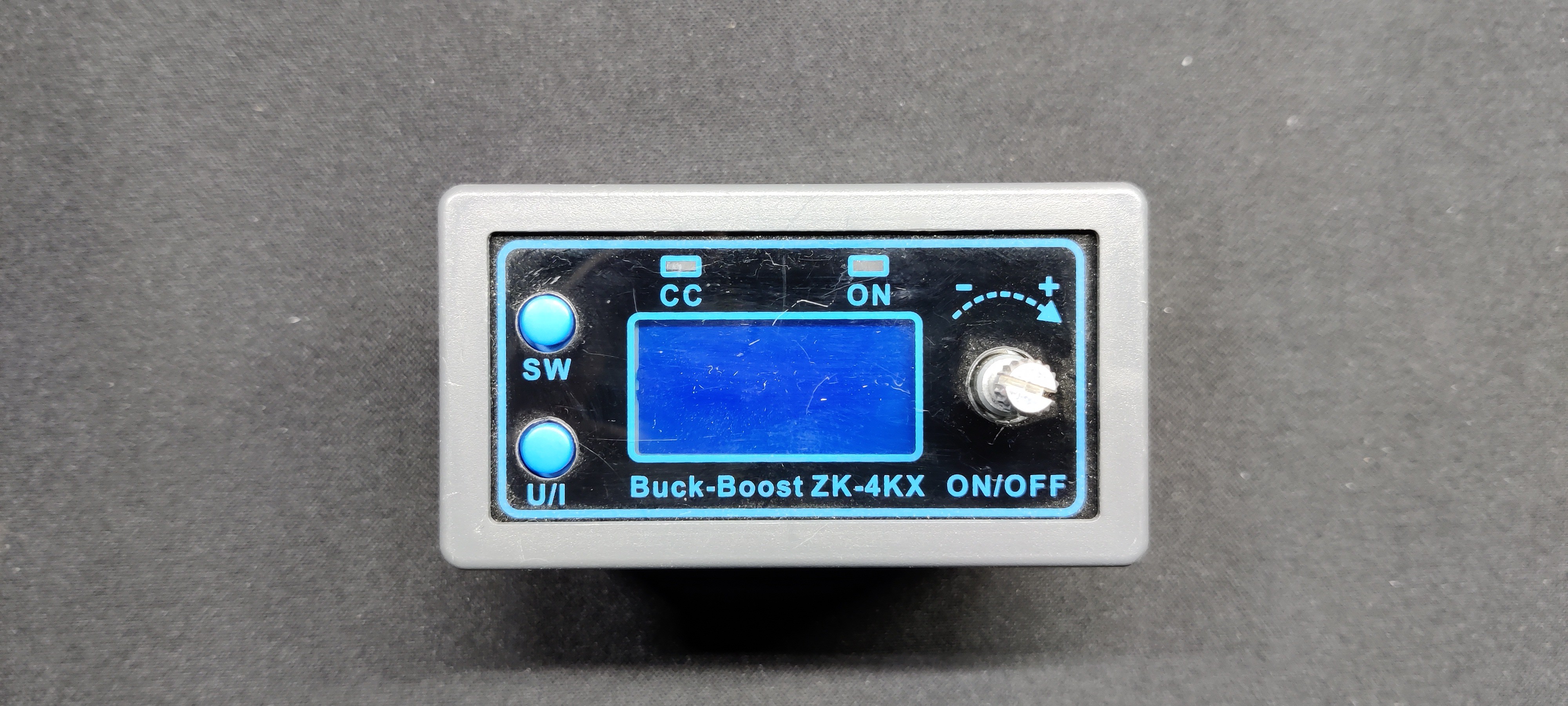
How to use:
The device operates by providing power to its input terminals; however, in order to turn on the output terminal, we must tap the rotary encoder button.
The output terminal's voltage can be set by using the rotary encoder.
The SET button has two main functions that are as follows: when pressed once, it indicates the amount of Ah utilized, and when pressed twice, it shows the amount of A that the load has used. The third tap changes it back to mA consumed by the load, and the fourth tap displays the W consumed by the load.
The U/I button is used for setting voltage and constant current. It can be seen that a certain digit of the output voltage value is flashing. Rotate the encoder left and right to adjust the major and minor.Short-press the rotary encoder to choose which bit of output voltage to set. After setting, press the U/I button 2 times to return to the normal interface. Or automatically return to the normal interface after stopping operation for 10 seconds.
Power Supply

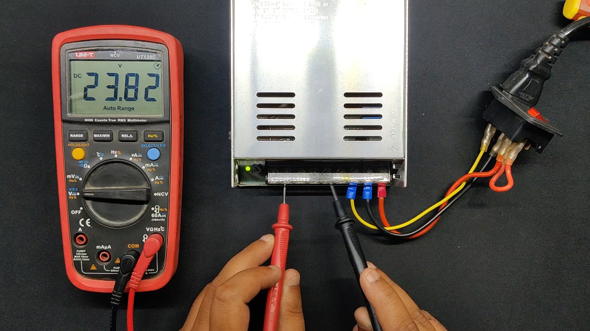
We are using an old 3D printer's 24V/10A power supply, which powers 24V servo motors, as our power source. Given that the ZK-4KX Module only allows voltage up to 30V, a 24V PSU was ideal for...
Read more »


 Denis
Denis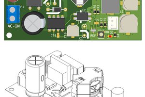
 hesam.moshiri
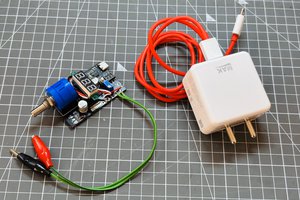
 Lithium ION