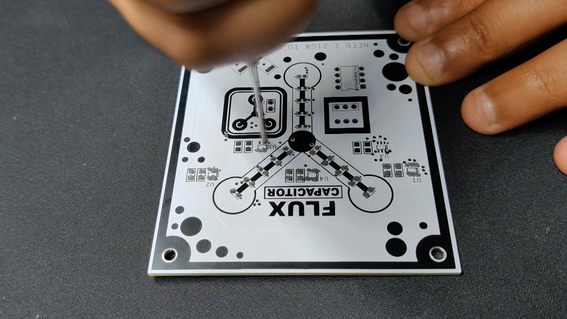
The PCB assembly process begins by first adding solder paste to each component pad.
Next, we pick and organize each SMD component after positioning it in its proper location.
After that, we set the board on our PCB hotplate reflow hotplate, which increases the PCB's temperature from below to the point at which solder paste melts, allowing the components to be soldered to their pads.
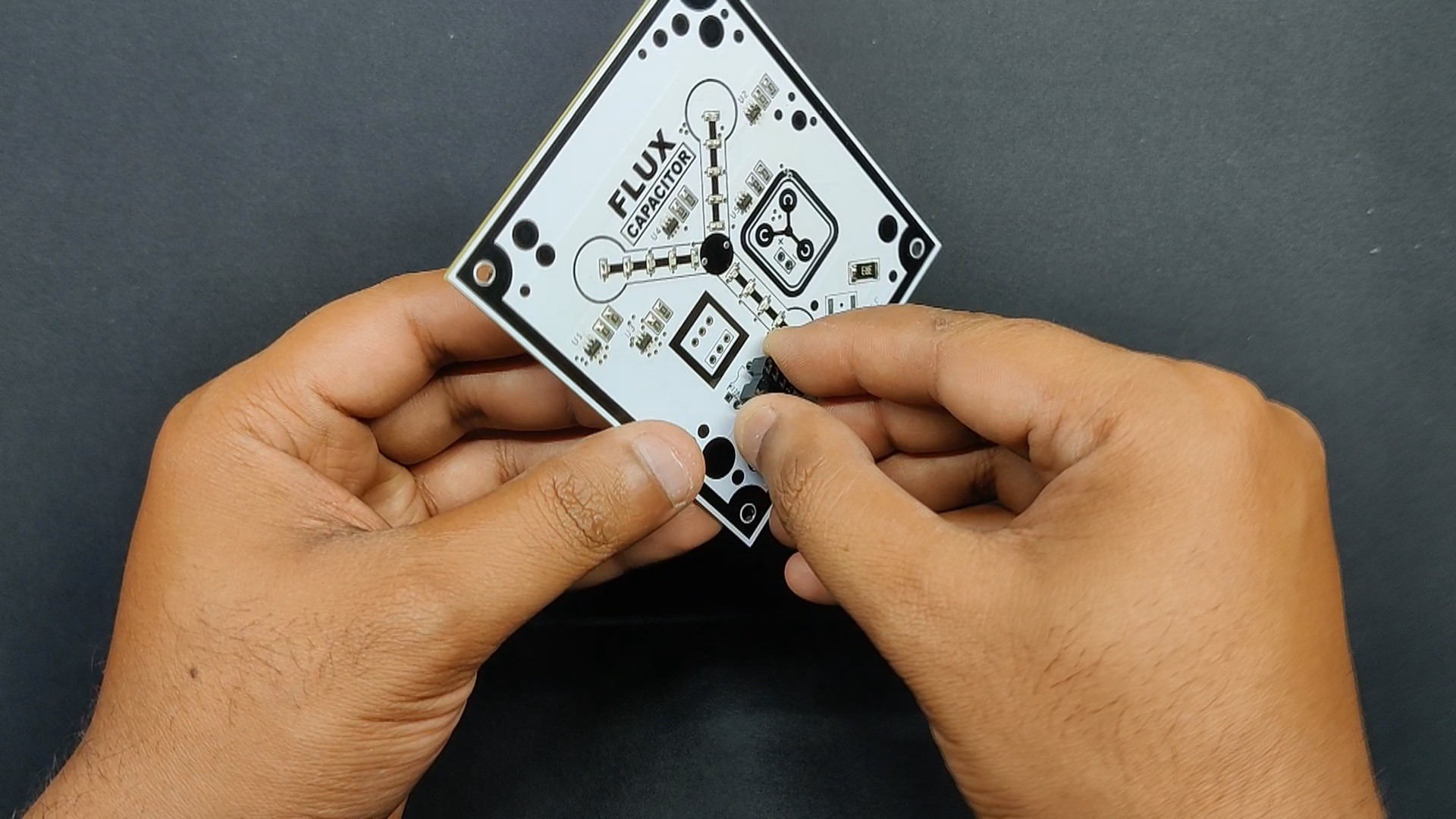
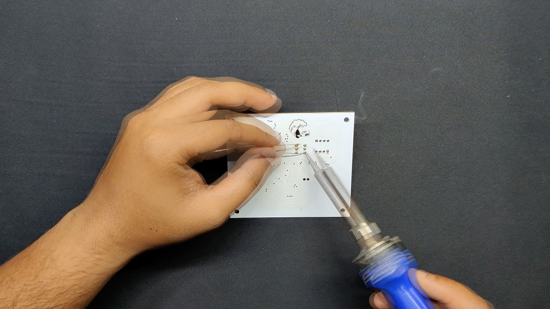
Next, we placed the Push Switch and DIP8 Socket in their proper locations and used a soldering iron to solder the respective pads.
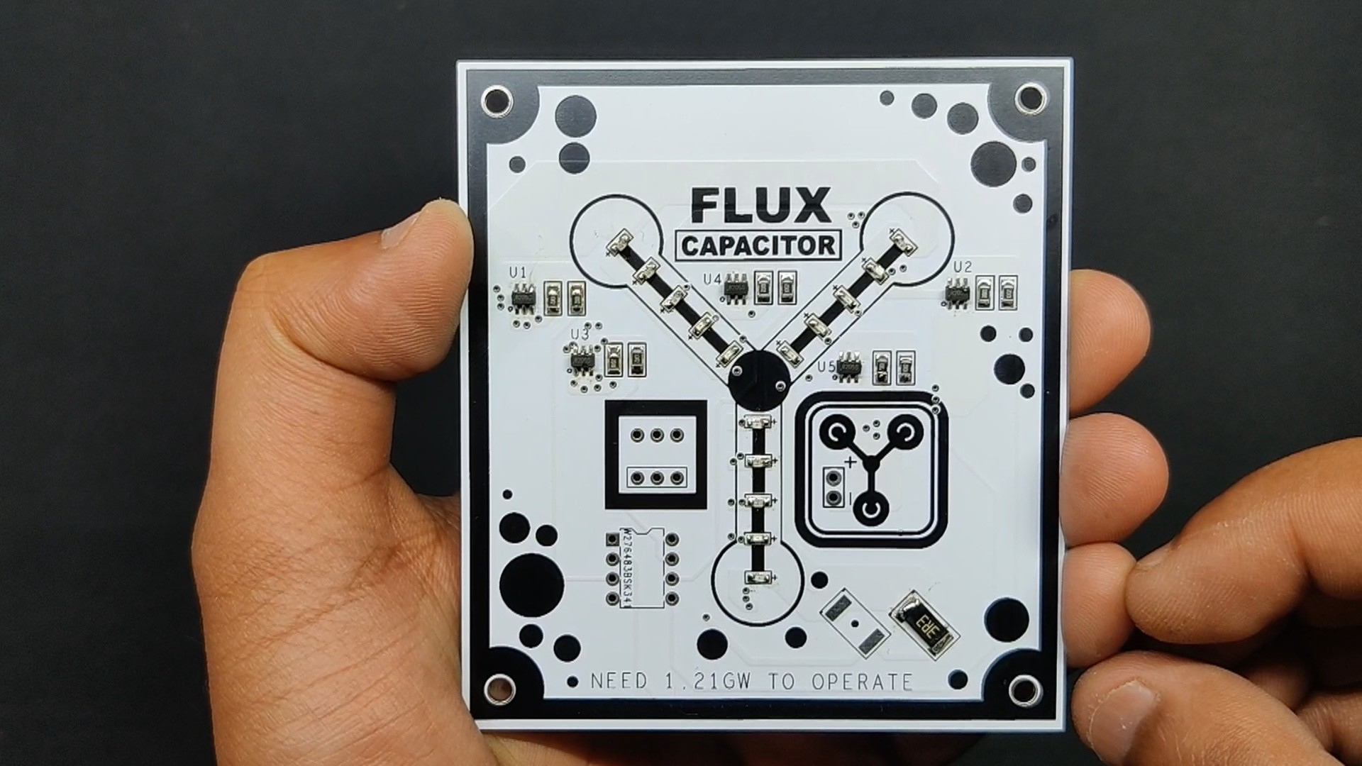
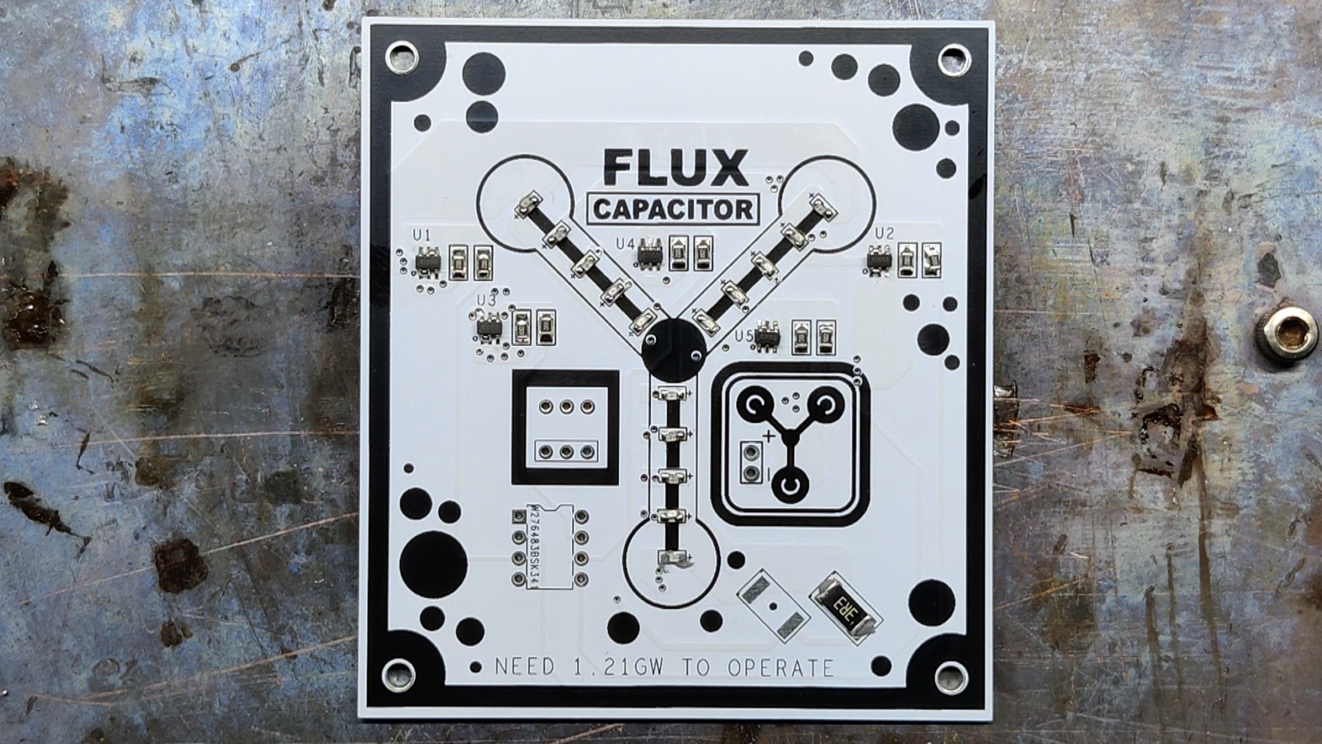
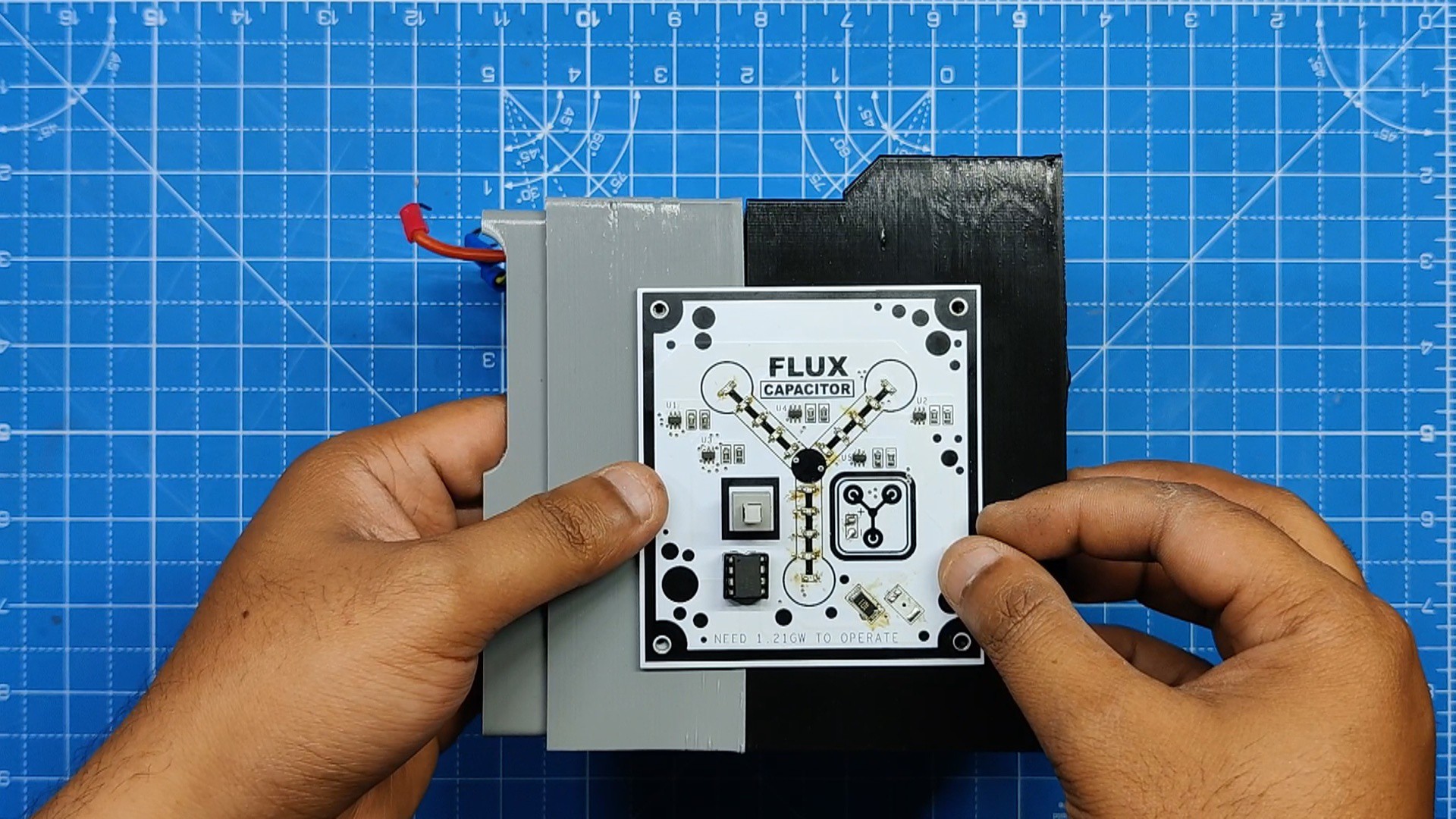
The board is now complete.
2
CODE and Flashing Process
This is the basic code that we utilize for this project. Five I/O Pins of the Attiny85 (D0, D1, D2, D3, D4) are connected to each of the five outputs that we are using.
This is a chaser sketch that exhibits a wave-like motion where light appears to be moving back and forth by sequentially toggling LEDs one after another.
int pinsCount=5; // declaring the integer variable pinsCountint pins[] = {0,1,2,3,4}; // declaring the array pins[]voidsetup() {
pinMode(0, OUTPUT);
pinMode(1, OUTPUT);
pinMode(2, OUTPUT);
pinMode(3, OUTPUT);
pinMode(4, OUTPUT);
}
voidloop() {
for (int i=0; i<pinsCount; i=i+1){ // chasing right
digitalWrite(pins[i], HIGH); // switching the LED at index i on
delay(70); // stopping the program for 100 milliseconds
digitalWrite(pins[i], LOW); // switching the LED at index i off
}
for (int i=pinsCount-1; i>0; i=i-1){ // chasing left (except the outer leds)
digitalWrite(pins[i], HIGH); // switching the LED at index i on
delay(70); // stopping the program for 100 milliseconds
digitalWrite(pins[i], LOW); // switching the LED at index i off
}
}
Flashing Process
Here, we first install the Attiy85 on the DIP8 Socket of the shield. (Note that the Arduino Nano on the ISP Shield has the ISP sketch flashed on it.)
Next, we install the Attiny85 Core files for Arduino by going to the below link.
After installing and setting up the core files, we go to tool menu and select the Attiny85 on board. We set the B.O.D to 1.8V and selected the programmer as "Arduino as ISP".
We then burn the bootloader, which takes up to 30 seconds to burn.
Once the bootloader has been burned, we select "Upload using programmer" from the sketch menu to upload the sketch to the Attiny85. The ISP flashing method does not support the regular upload method.
3
Power Source for Flux Capacitor Board
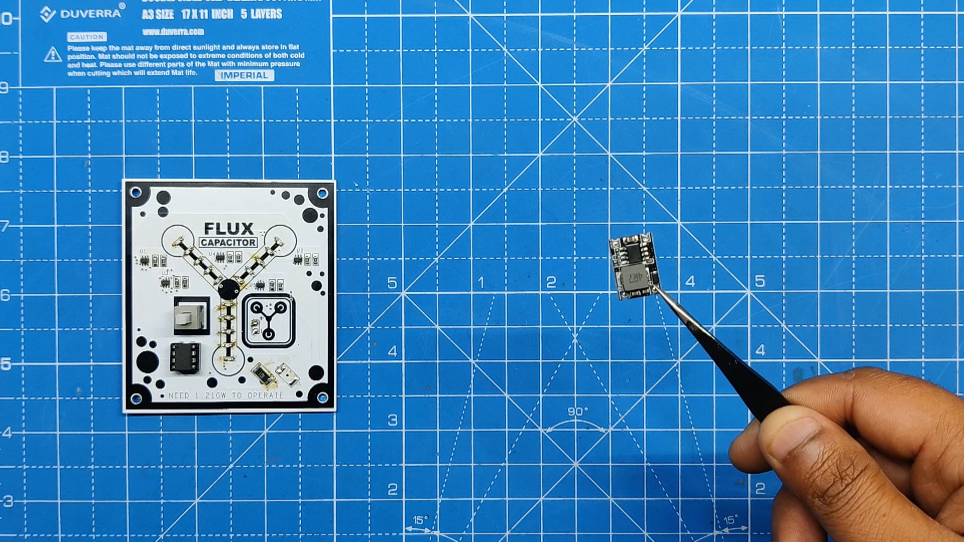
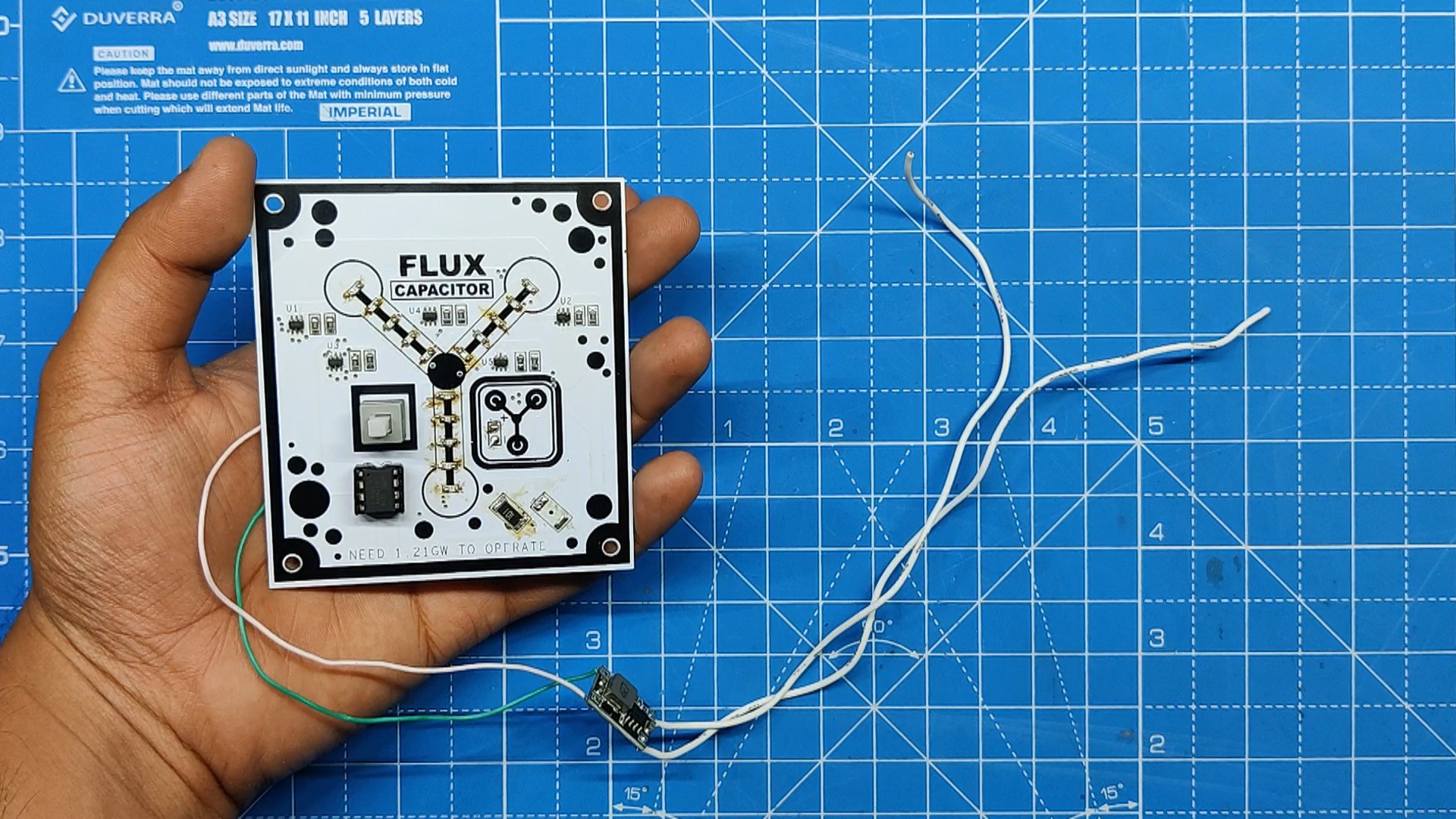
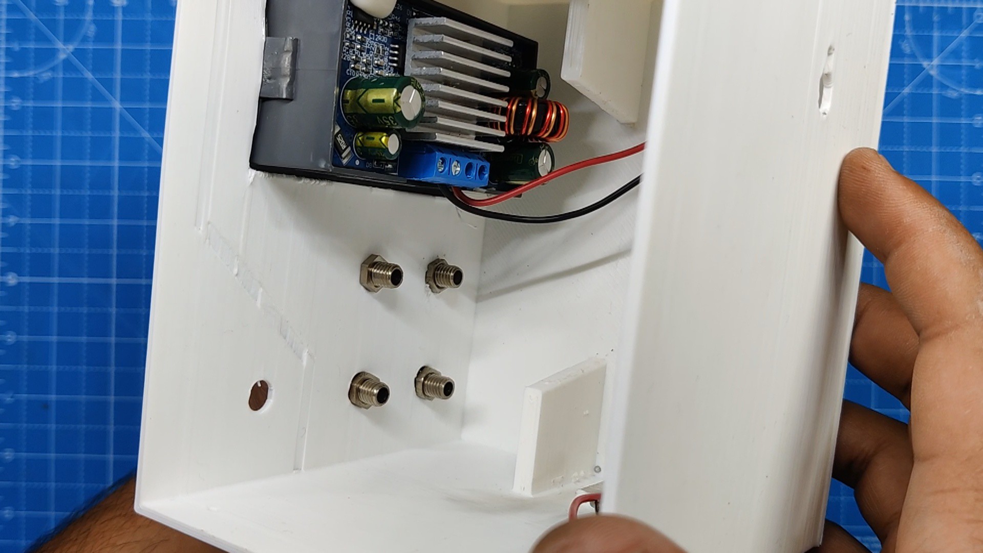
We use a DC-DC Buck converter module, which runs at 7–26V and can provide a constant 5V, to power the flux capacitor, a 5V device, from a 24V supply.
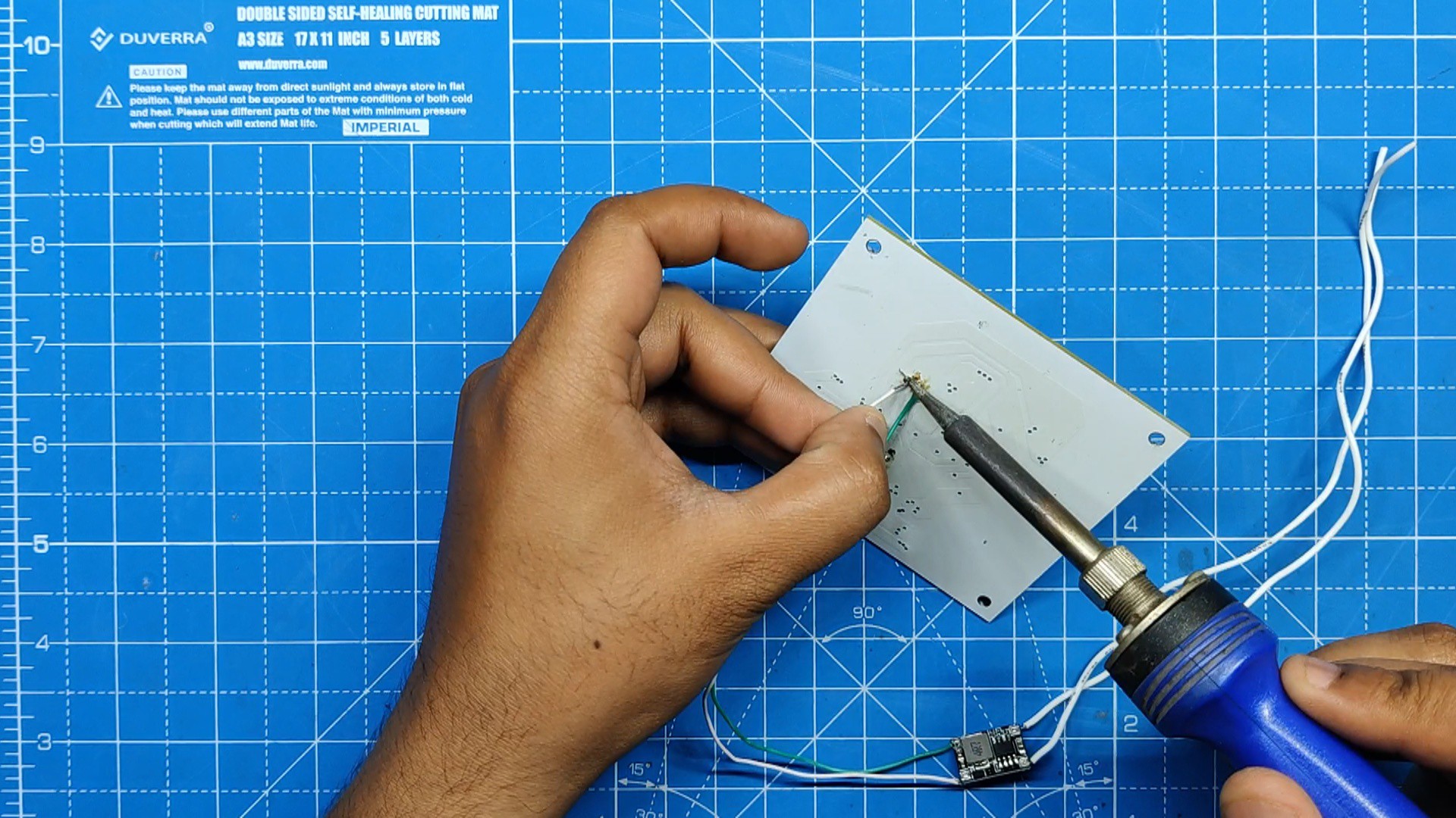
Here, we connected the DC DC Buck module's output wires to the VCC and GND of the flux capacitor board after adding wires for the module's input and output using a soldering iron.
4
Basic Setup
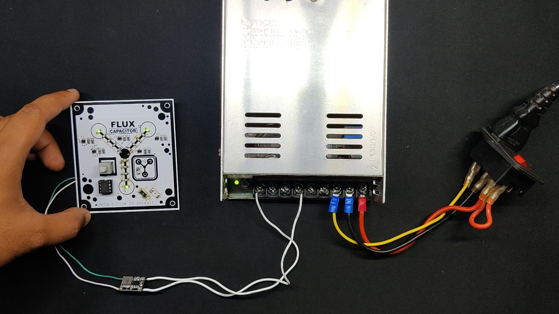
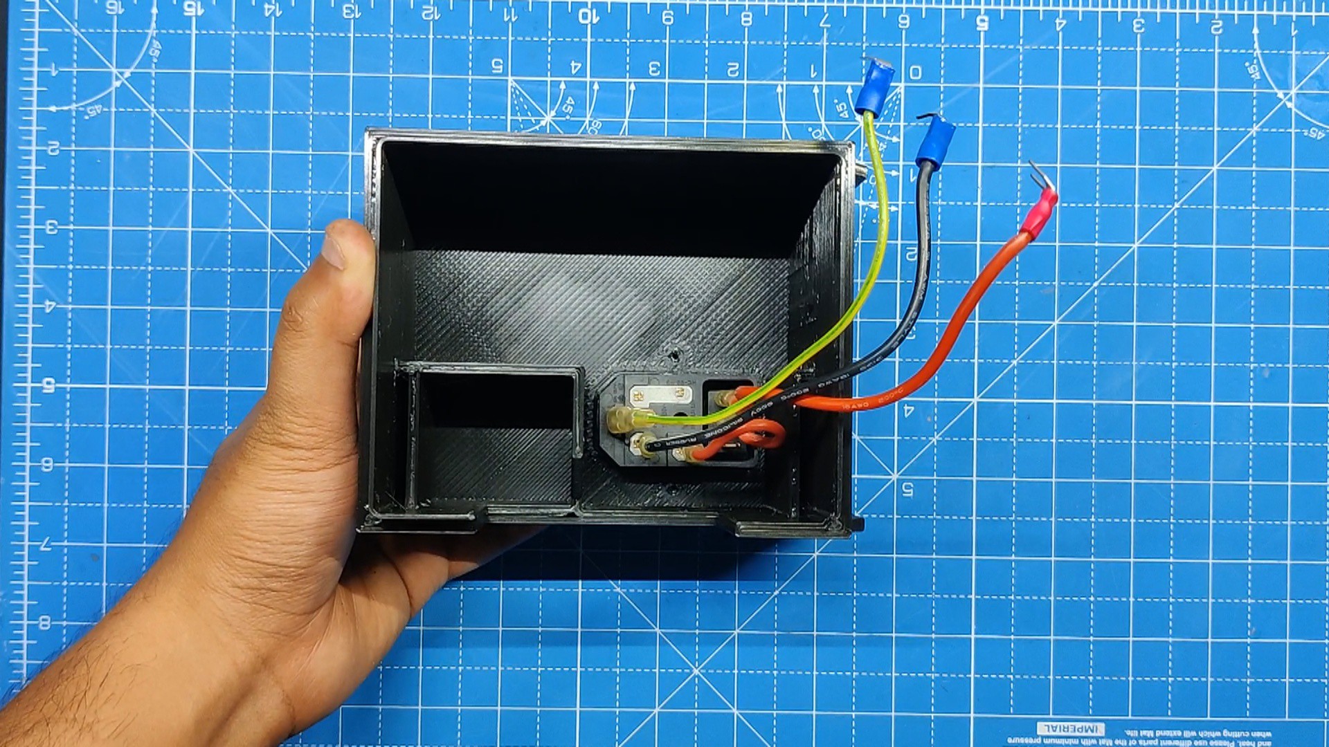
We added the Power Inlet's Live, neutral, and earth wires to the PSU Live neutral and earth port.
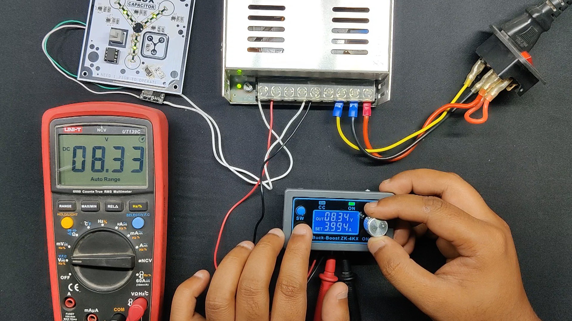
Next, we use a multimeter to measure the SPMS's output to see if the setup is working or not.
Next, we attach the input wire of the DC-DC Module to the power supply's GND and 24V + ports. The flux capacitor board is powered in this way.
We also added the ZK-4KX module's input connections with 24V+ and GND in a similar manner.
We connected the positive and negative probes of a multimeter to the output connector of the ZK-4KX Module in order to measure the output voltage of the ZK-4KX Board.
Both the ZK-4KX and the flux capacitor appear to function when the Power Inlet switch is turned on.
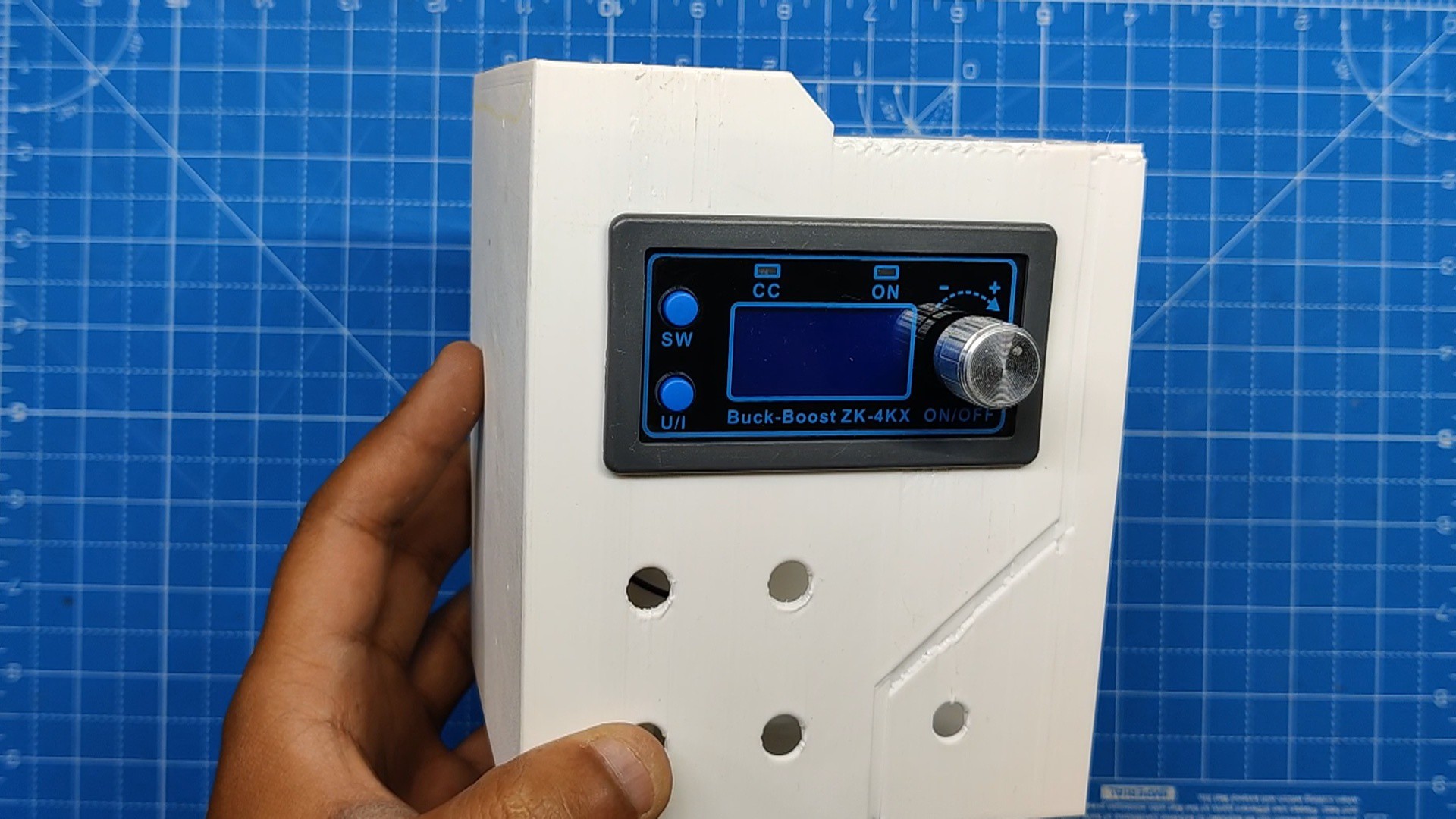
We turn the ZK-4KX Module's knob and see that the multimeter displays the same reading as what is displayed on the module's screen.
Now that the setup is working, we can begin the assembly procedure.
5
Assembly Process: Output Section
The assembly process began with setting up the output section and inserting the ZK-4KX module into the designated body slot.
We next insert the female banana pin connector into the four holes on the body and tighten them firmly with the provided M4 nut.
The banana pin has a washer-like part that we can solder wires to and make connections on. To that end, we connected two washers together by soldering the pads on them. We then added extra wire to link the washer-wire assembly to the ZK-4KX converter module's output terminal.
We create a total of two washer-wire assemblies, each of which is positioned behind the banana pins that have been inserted to the output section body. The banana pin will be connected to the ZK-4KX Module's positive and negative output terminals via these two washer wire assemblies.
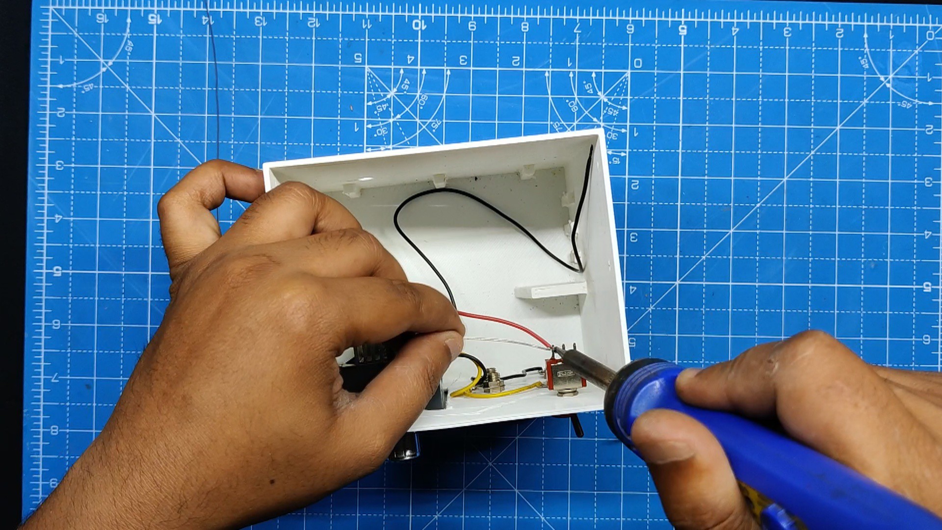
The toggle switch was then inserted and tightened into the body's designated hole.
Next, we connected the toggle switch to the ZK-4KX module. This switch is designed to break the positive line that connects the module's input to the power supply.
6
Assembly Process: Power Input Section
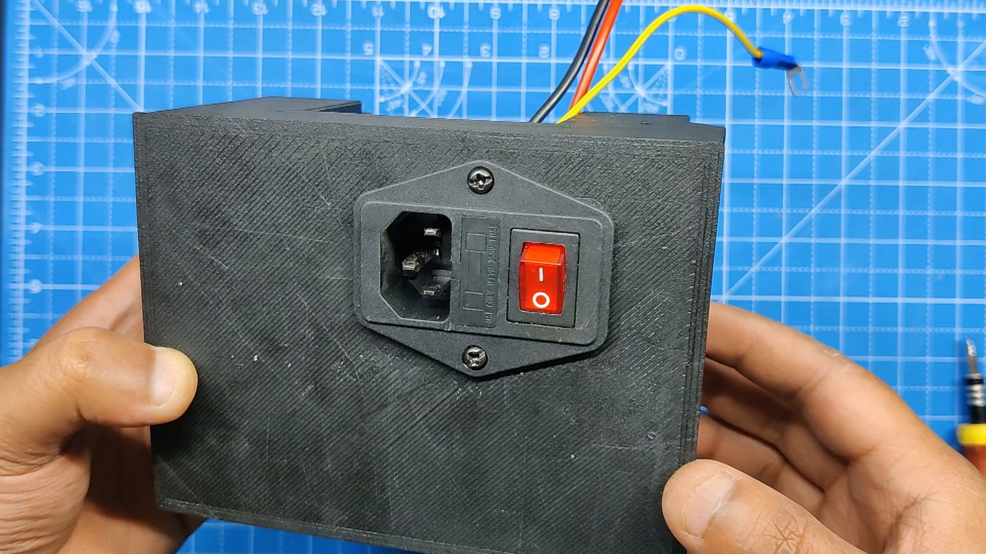
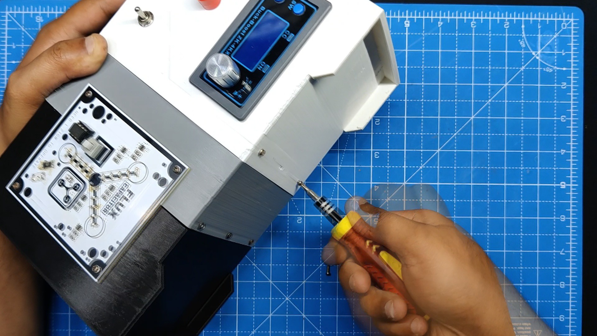
Starting with the Power Inlet and fastening it with two M3 screws, we now begin the assembly of the Power Input Section.
Using six m2 screws—three on the bottom and three on the top—we then joined the middle section and the power input section.
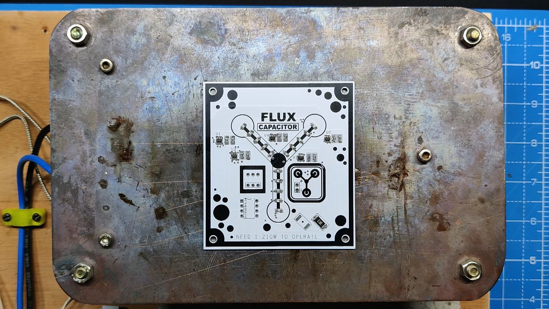
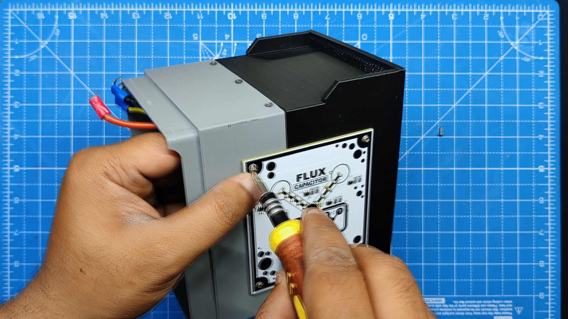
On the front face of the Power Input-middle section assembly part, we then position the flux capacitor PCB in its proper location.
The flux capacitor PCB is fastened to its location using four M2 screws.
7
Final Assembly
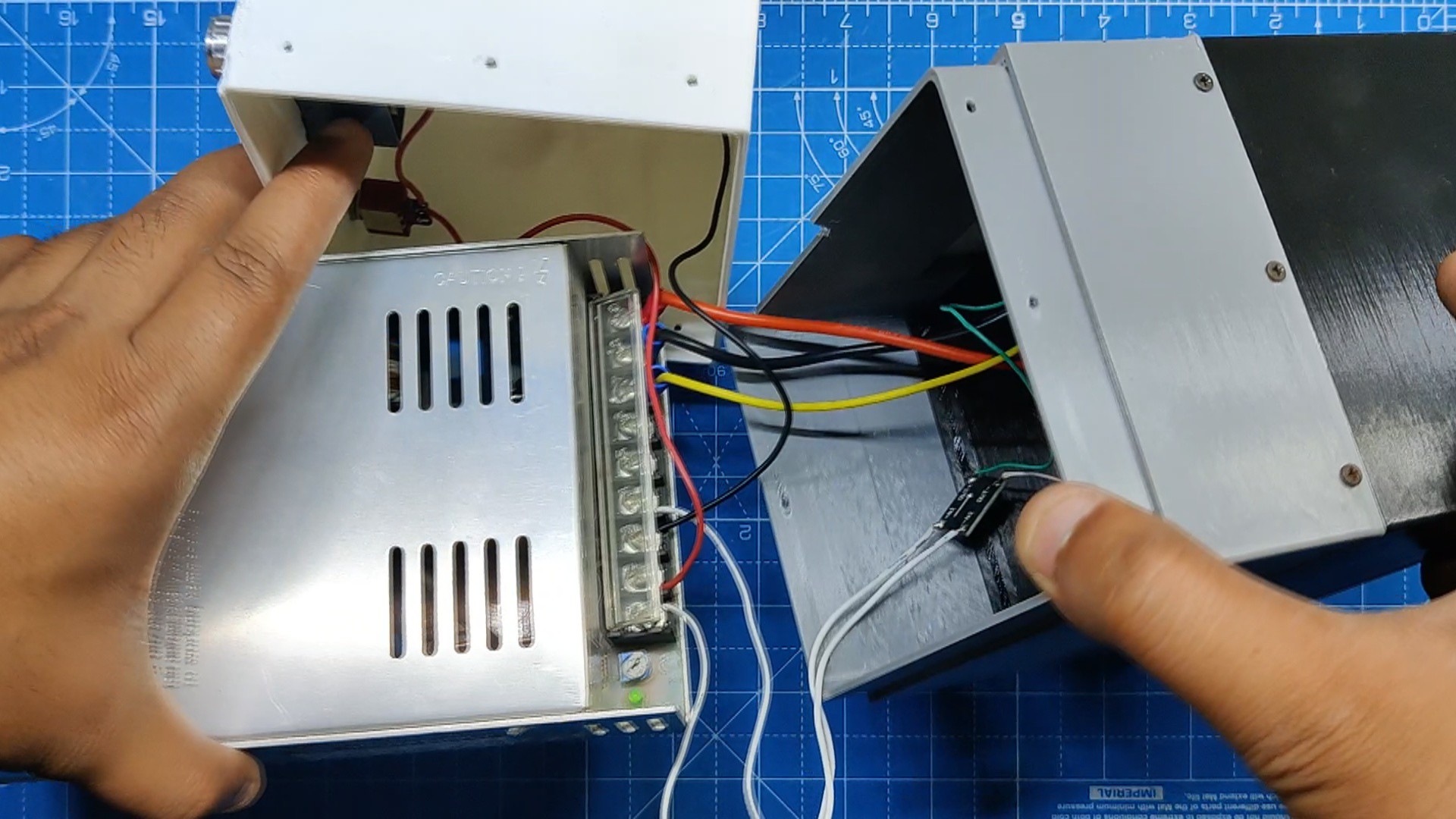
The live neutral and ground wires are connected to the SMPS terminals to initiate the final assembly process, which involves connecting the SMPS to the Power Input section.
The DC-DC buck module's positive and negative were then connected to the SMPS's +24V and GND terminals. (The flux capacitor PCB is powered by the DC-DC Buck converter.)
Next, we connected the ZK-4KX's input terminal to the SMPS's 24V + and GND inputs. The wiring is finished now.
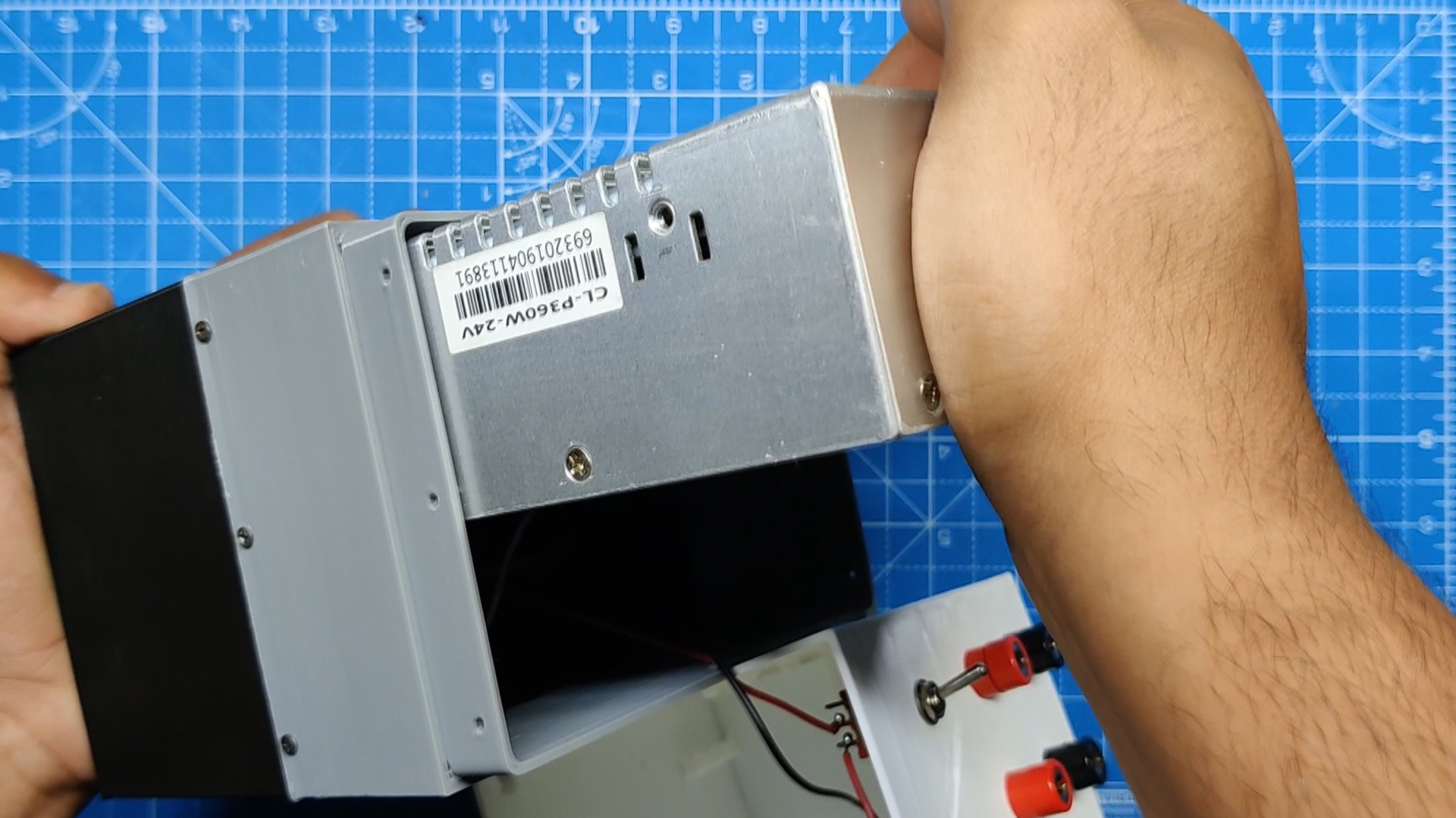
Now, we slide the SMPS into the power input section.
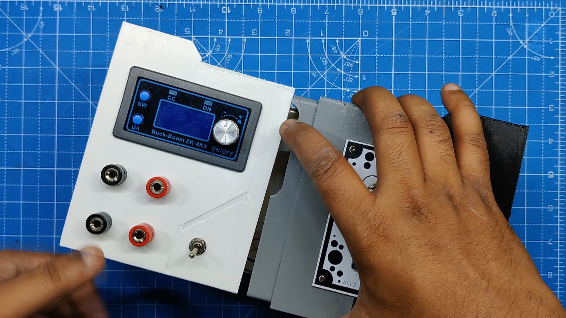
On the opposite side, we added the output section to the power input section. SMPS is now secured between these two sections.
Next, we use six M2 screws to attach both sections together.
The assembly is now complete.
8
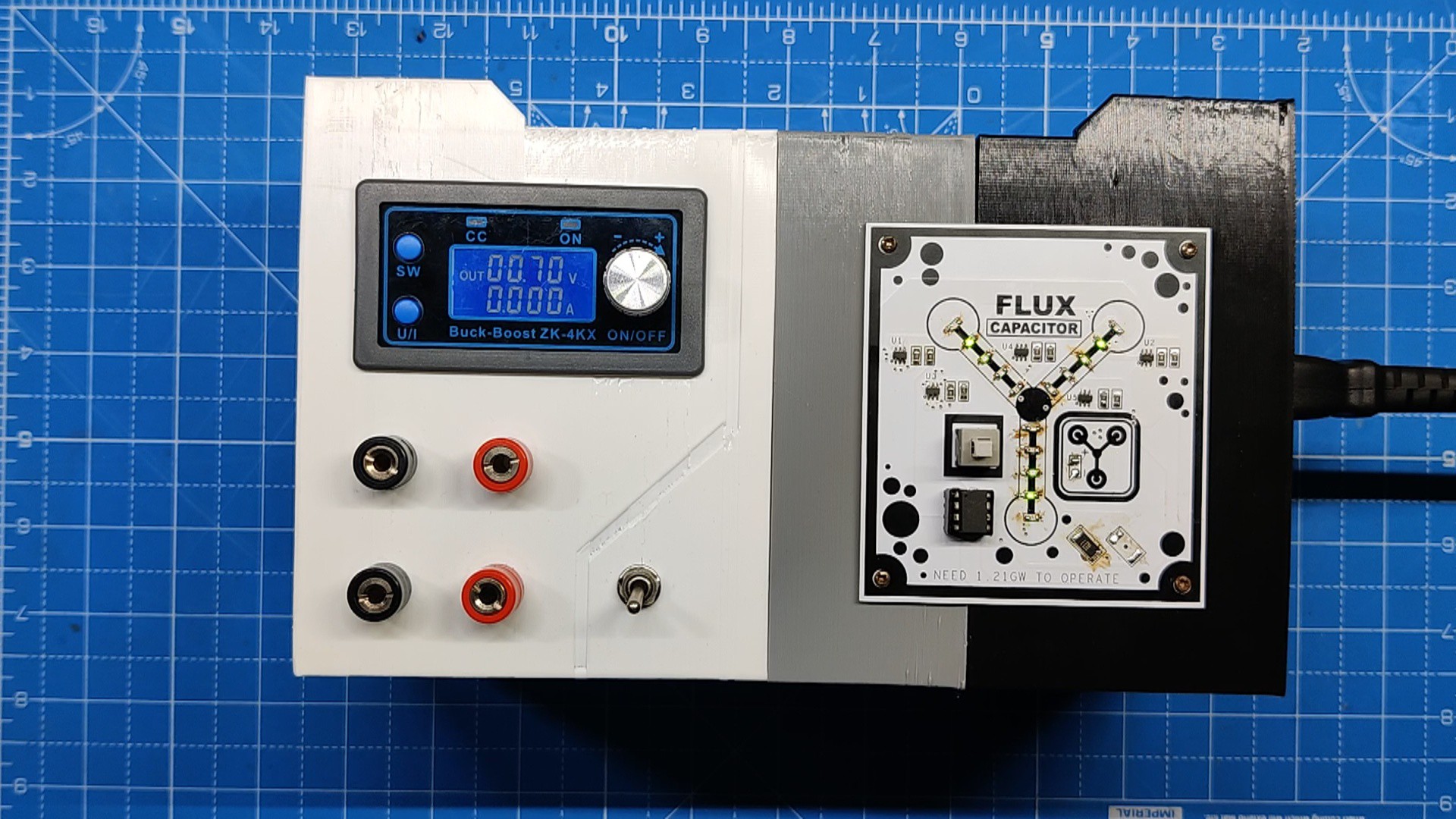
Result
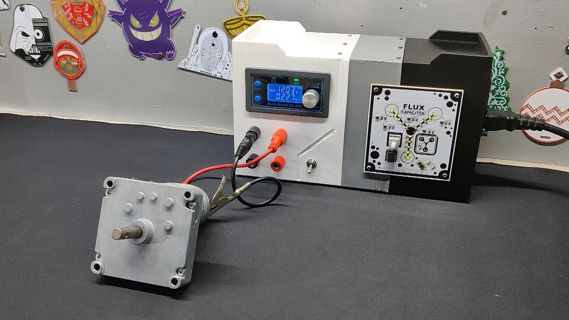
The result of this project is this DIY bench power supply that was put together from scratch using a few components. Here, we used a 3D printer's salvaged SMPS to power both the flux capacitor circuit and the ZK-4KX module.
In order to test this setup, we operate a 12V Gear DC motor by connecting the motor's power terminals using the banana pin that is attached to an alligator clip.
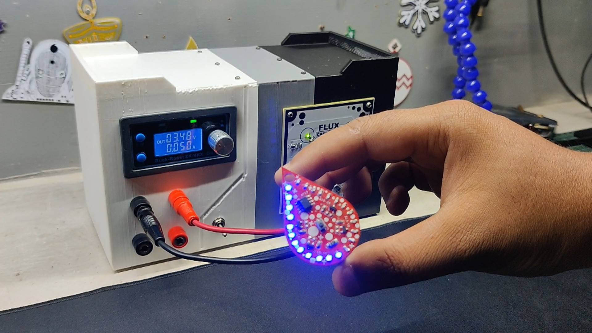
In the same way, we powered on our previous LED badge project, which utilized 3.4 volts. This device's low 50 mA consumption was shown on the ZK-4KX display.
The ZK-4KX Module can be used to drive a variety of loads with constant current or voltage while monitoring a number of parameters, such as power consumption, power, current, and temperature—all of which are quite helpful.
We are utilizing the ZK-4KX BUCK BOOST Module here, but the DPS3003, a well-liked substitute with a colored display and smart interface that is more user-friendly and offers more readings and a few other capabilities, is a similar buck boost module. Since the two modules are the same size, someone with a somewhat larger budget can simply replace the ZK-4KX with a DPS30003.
This bench power supply should last at least five or six years, but we will have to wait and see.
Overall, this project was a success and needs no further revisions.
 Arnov Sharma
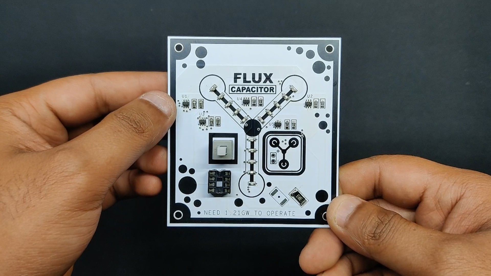

Discussions
Become a Hackaday.io Member
Create an account to leave a comment. Already have an account? Log In.