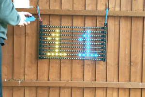
As promised in my YouTube videos, here I present an example of driving a NeoPixel LED strip from the Linux core of the Milk-V Duo.
This example was developed on a Duo-256m but I am quite sure it would work on the Duo-64m as well.
Methodology:
There are several methods to produce the timing pulses required to light the NeoPixels on an LED strip. Because the Duo has more than ample compute power, memory and a flexible SPI peripheral, I chose to highlight the use of the latter.
The basic principle is to select a clock rate of 2.5 MHz to allow for pulse widths in multiples of 400nS. Then transmitting a binary '4' gives the timing needed for a Zero, and a '6' gives us a One. So we end up with what I call "NeoBits" which are actually 3 bits long.
Although these strips are sometimes referred to as addressable LED strips we cannot access individual pixels randomly. They operate more like serial memory. To change a single LED we need to send the entire pixel array every time we make a change. So a serial stream of 24 NeoBits representing the RGB value of each pixel must be sent. This means a minimum of 24 x 3 x 15 = 1080 bits for a 15 pixel strip. In the case of this example, to make calculations and mental visualizations easier I actually used 4 bit NeoBits just by spacing them out in the array. The entire array is developed in memory and transmitted in a single SPI transmission, followed by a minimum 50 uSec delay which indicated to the strip that the serial update is complete.
Some Hardware Considerations:
NeoPixel strips are definitely 5V devices, whereas the Duos output 3V3 at most. So we need some type of level shifting. The NEOs are also sensitive to the signal quality. They do have their own built-in signal conditioning when passing data from one pixel to the next. But you can come across problems of unpredictability with the first pixel. A Level Shifters or a simple transistor with a couple of resistors are some options, but I found that using a Schmitt trigger TTL chip like the 74HC14 does both jobs very well. (74LS14 is even better). We can feed the inverter input of the '14 with 3V3 from the SPI MOSI signal and because the chip is powered from 5V it provides the level shifting. The hysteresis of the Schmitt trigger provides an ideal signal clean-up. We just connect MOSI to pin 1 of the '14', connect pins 2 and 3 together to get the double inversion, then connect pin 4 to the DATA input of the NeoPixel strip.
As I am sure that you are aware, these strips can consume considerable power depending on how many pixels you are lighting up, as well as the brightness of each pixel. So, of course, it is highly advisable to use an external 5V power supply rather than use the 5V pin on the Duo. (although this is what I did in my testing on a 15 LED strip, taking care to use lower brightness).
Software Considerations:
To create this example I used the 1.0.9 boot SDcard image. I had hoped to use the /dev/spidev convention to manage the SPI device but struggled to find easy examples and documentation so I am using the wiringX library instead. This works quite well - the output observed on the logic analyzer did not appear to have any room for improvement. There was one issue though. I started by using 'normal' SPI conventions like beginTransaction and endTransaction, toggling the CS line in each case. This was very helpful for syncing the logic analyzer but revealed a drawback of using wiringX. The digitalWrite call is very slow, typically introducing 40 - 60 uSec of delay. These delays were a killer - anything over ~ 50 uSec is considered by the strip to signal the end of transmission. So I was getting very unpredictable results with respect to the number of LEDs that lit up. Once I was convinced that my timing was correct I removed the digitalWrites to the CS line and every thing worked reliably.
When setting up wiringX we do...
Read more » CanHobby.ca

 LordGuilly

 Gilhad