Dylan Brophy
-
Text is looking good :)
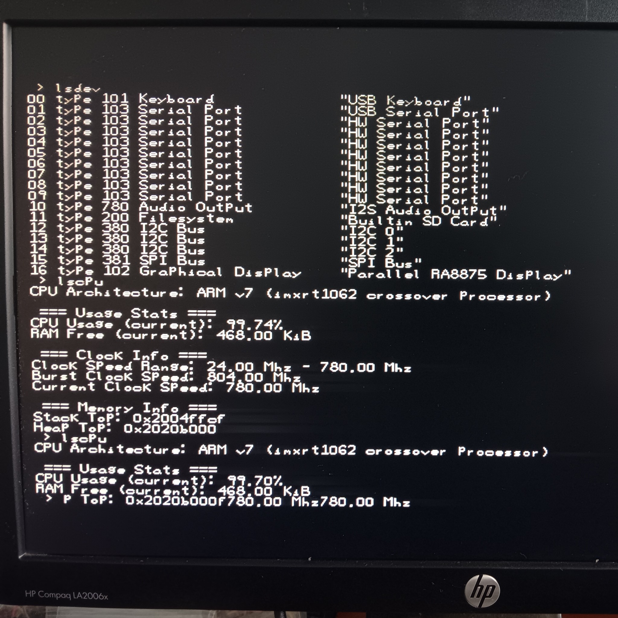
08/15/2024 at 03:36 • 0 commentsI've got the #Arduino Desktop running the card and a keyboard, so I have an actual interface/prompt now. The text is looking pretty good, but there are streaks from the text so there must be something messed up in the video signal.
![]()
There is some trailing white blur after the text, so I wonder if the voltage on the RGB lines is not dropping as fast as it should or something. Here I ran some commands to test out the text.
Just last night or so I didn't even have the pixels working right, and to be completely honest, I have no idea exactly what made the pixels want to show up. My theory is that adding a software reset before initialization fixes it, but I don't really know, and due to the nature of resets it's not the easiest thing to test. Whatever, it works, and it seems to work consistently. Here's the reset code:
writeCommand(RA8875_PWRR);
writeData(RA8875_PWRR_SOFTRESET);
writeData(RA8875_PWRR_NORMAL);
bootloader_delay(1);
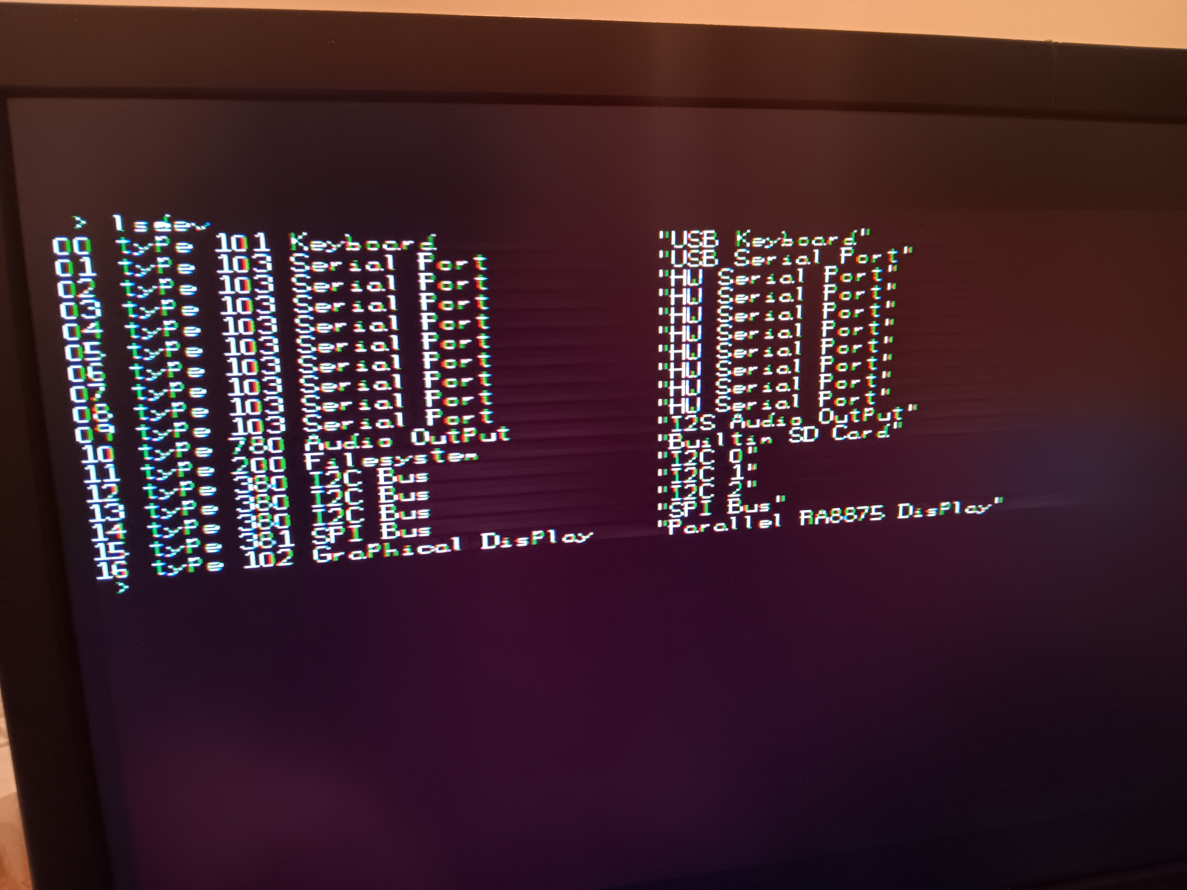
Now, when I did get the pixels working, it was still messed up:
![]()
It's hard to tell in the picture, but the pixels are not exact and kinda messed up. The video quality also changed when I touched the back of the board, which would seem to indicate a signal integrity issue. In fact, it seemed that many of the pixels were dropped completely, but there was a pattern to it, so the text was still somewhat legible. I thought the RA8875's connections to the PCB must have been bad, which made *some* sense, since I had replaced the RA8875 chip twice and there wasn't much solder left on the pins. I checked this, and the video did look a little better, but it still was wrong. I decided to try changing the pixel clock polarity, and this fixed the problem. Again, the relevant code:
GraphicsDisplayDevice* initVideoCard(ParallelBusDevice* bus) {
  timing_params_t timing;

  timing.pixclk = RA8875_PCSR_PDATR;
  timing.hsync_nondisp = 88;
  timing.hsync_start = 40;
  timing.hsync_pw = 128;
  timing.hsync_finetune = 0;
  timing.vsync_nondisp = 23 + (600 - 480) / 2;
  timing.vsync_start = 1 + (600 - 480) / 2;
  timing.vsync_pw = 4;
  timing.voffset = 0;
  timing.width = 800;
  timing.height = 480;

  // SYSCLK = ((PLLC1 & 15) + 1) * 20Mhz / 4
  // For PLLC1 = 7, SYSCLK = 40Mhz
  timing.PLLC1 = RA8875_PLLC1_PLLDIV1 + 7;

  return new RA8875Parallel(bus, &timing);
}
This is the correct code to make the RA8875 output a valid 800x480 VGA signal. I based it on my experimentation, and on the tinyvga site, which is a great resource by the way: http://tinyvga.com/vga-timing/800x600@60Hz
The timing I'm using is for 800x600, but I lengthened the vertical porches to make up the difference in y resolution.
-
Drawing (badly) to VGA Monitor!
08/14/2024 at 04:01 • 0 commentsSo, my design idea WILL work! I did have my doubts, but it turns out it will actually work. Here is what it's drawing, which should be text, but clearly isn't:
![]()
There is this white strip, which is basically a rectangle where the text should be - like it's filling it. I don't know exactly why it's doing this yet, but it probably has to do with my setPixel routine, which is used for drawing the font:
void RA8875::setPixel(int x, int y, uint16_t color) {
	// The actual pixel write code doesn't draw anything at all
	/*writeReg16(RA8875_CURH0, x);
	writeReg16(RA8875_CURV0, y);
	writeCommand(RA8875_MRWC);
	writeBytes((char*)&color, 2);*/

	// At least this draws *something*
	fillRect(x, y, x, y, color);
}
The setPixel should write directly to the display memory, but for some reason the direct write to memory is not working. So I decided I would try just drawing rectangles to temporarily solve this issue, which clearly didn't work either. I'm still investigating it, but from the looks of it, the corner of the rectangle is probably always starting at coordinates 0, 0 for some reason. Here's the related code:
void RA8875::fillRect(int x1, int y1, int x2, int y2, uint16_t color) {

	int x = min(x1, x2);
	int y = min(y1, y2);
	int w = abs(x2 - x1) + 1;
	int h = abs(y2 - y1) + 1;

	// I'm suspicious of 16-bit register numbers not divisible by zero...
	writeReg16(0x91, x);
	writeReg16(0x93, y);
	writeReg16(0x95, w);
	writeReg16(0x97, h);
	writeColor24(color);

	writeReg(RA8875_DCR, 0xB0); // Use 0x90 if you just want to draw the edges

	// Wait for the command to finish
	waitPoll(RA8875_DCR, RA8875_DCR_LINESQUTRI_STATUS);
}
Really, none of this seems out of the ordinary other than the odd register numbers. I'll need to study the datasheet a bit more.
The important part, is that the design fundamentally can work.
The main thing I was missing since last log, was that I didn't turn on the display in my code. I thought this was just for the LCD backlight driver, but turns out there won't be any color without turning the display "on" either. I guess that sorta makes sense, although it is strange that it would still send the sync signals without the color data. Again, here is the relevant code:
writeReg(RA8875_PWRR, RA8875_PWRR_NORMAL | RA8875_PWRR_DISPON);
This code was based on Adafruit's RA8875 library, which works great if you are using a SPI interface. This code also seems related to this repository, and I am not sure how they are related, but it is another good repository to look at for RA8875 driver code, and really any LCD driver - there are a LOT of drivers supported: https://github.com/ZinggJM/GxTFT/blob/master/src/GxCTRL/GxCTRL_RA8875P/GxCTRL_RA8875P.cpp
I integrated ideas from both of these sources, as well as added/modified some of my own. I felt they both deserve credit, and also are just good reference points for anyone else. If you are interested in the driver I am writing, the source is here: https://git.nuclaer-servers.com/Nuclaer/ntios-2020/-/blob/cb48037977205ada23a78f7c474f36f2d2665fa2/drivers/graphics/ra8875.cpp
The commit, as of this log, is 14837b6.
-
It's Alive!
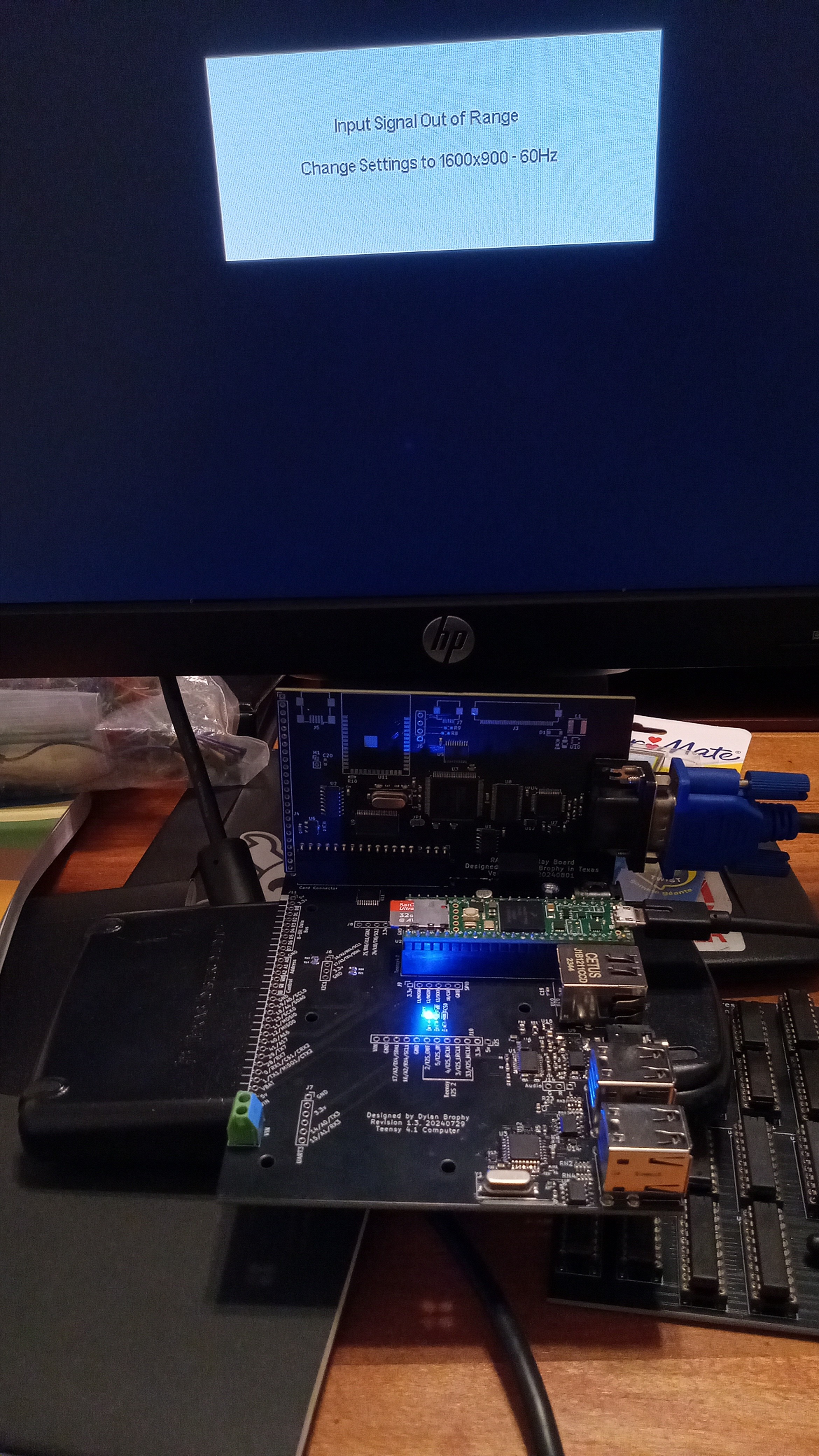
08/13/2024 at 03:43 • 0 commentsI have successfully connected the new board to the new Teensy-based #Arduino Desktop, and although I do not have a *valid* signal yet, I do have a signal, and the data exchange is working :-)
![]()
Obviously, at this point, I have assembled the PCB. There was a PCB bug, screwing up the direction of the level translator, but after fixing this I was able to communicate with the RA8875.
Based on the Adafruit RA8875 library (https://github.com/adafruit/Adafruit_RA8875), it seems we can query register 0 and should expect 0x75 to be returned, to confirm proper connection. Sure enough, this worked exactly. After this, we can initialize the video registers. I just used Adafruit's settings for their 480x800 displays. At some point while loading the registers, the attached monitor woke up and told me the signal was invalid - which indicates that I am actually sending at least the sync data over the wire, even if incorrectly!
This all was after connecting the RA8875 IC backwards, of course. Well, it still worked after I flipped it despite this abuse, so I'm grateful.
The next thing for me to do is write a small library for talking to it, or perhaps a library for #NTIOS. The initialization sequence doesn't look too complex, if anything it will just be difficult to get the right settings.
-
Board Assembly
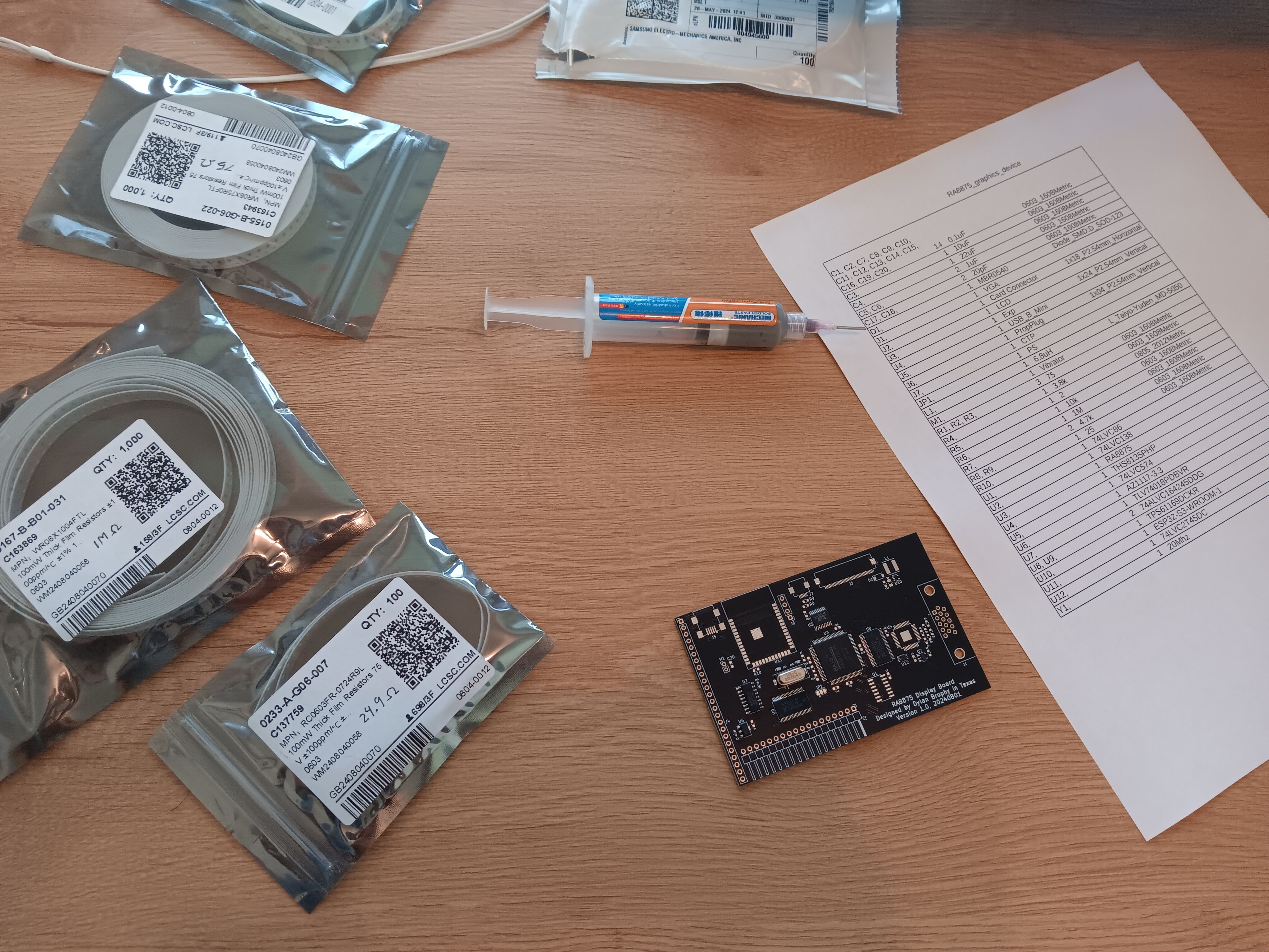
08/09/2024 at 21:53 • 0 commentsI'm assembling a prototype for this board, which *hopefully* will provide working VGA output:
![]()
Circuit board assembly on my kitchen table I'm missing just three components, which includes the video DAC, so sadly I will not be able to test until tomorrow. I just want to get it rather close to assembled today, to get ahead of it. I created my cart on mouser, and forgot to check out, until I realized I was missing something; you know how it goes.
I'm configuring this one for VGA only, so I'm not installing any of the LCD circuitry, like the backlight driver or LCD/CTP connectors. I'm going to connect it to my #Arduino Desktop, so the ESP32 will not be needed either. Altogether, this assembly will be rather simple. Soon I'll also assemble one for LCD only; hopefully everything works perfectly.
RA8875 VGA
Let's use a LCD driver to drive a VGA monitor. It sounds fun.