 zakqwy
Z-axis design has reached the lead screws! The gantry frame will constrain one end of the the X-axis lead screw in all degrees but rotation, and the opposite side will probably just include some axial preload for the lead screw support bearings. To avoid overconstraining the carriage, the lead screw nut needs a bit of radial compliance. I also want to preload the nut axially, so on the far side of the radial compliance I also need to support a second nut and add axial compliance with some means to adjust force. And it all has to be quite small!
Here's a first test:
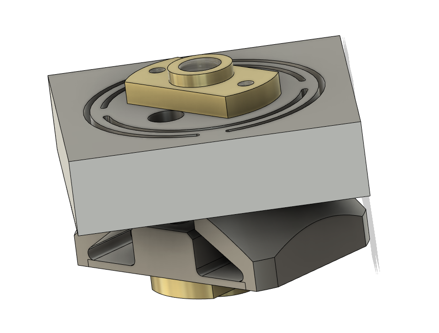
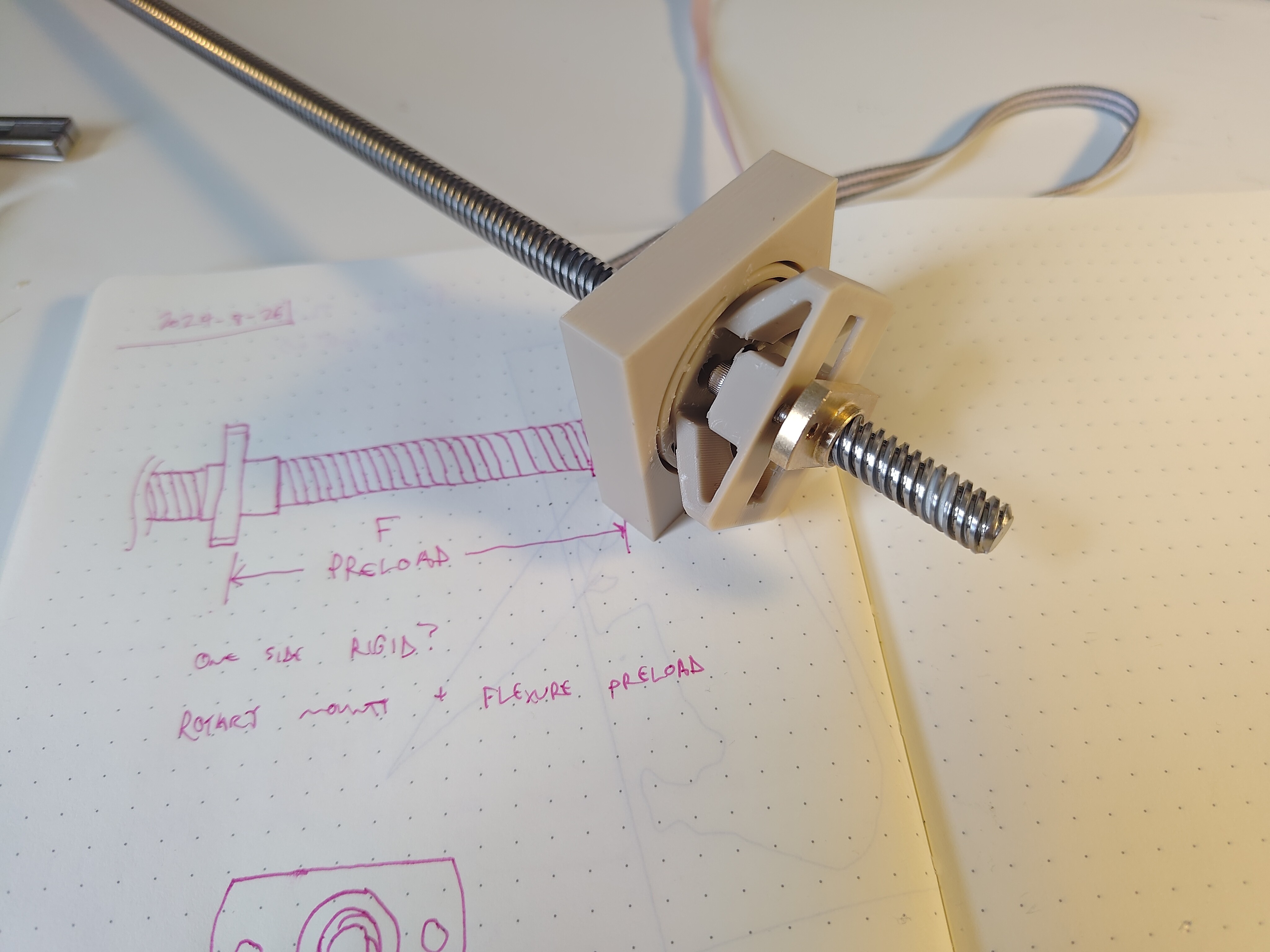
This worked pretty well! The extra space between the base of the preload nut and its support didn't matter, since all that nut needs to do is exert axial force against the lead screw. This could be simplified and shrunk down quite a bit since I really don't need to rigidly mount the preload nut to PLA. I like being able to adjust the preload with a hex driver, and could always add a jam nut to keep the setting.
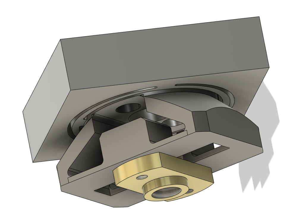
I added a bit of lithium grease and was able to make backlash quite difficult to detect by manually pulling the lead screw out, but this required quite a bit of tightening. I was able to snug the preload bolts down two full turns and could still rotate the lead screw (albeit with some difficulty), so I may try thickening up the flexures a bit so the preload is stiffer. I need to add a bit of clearance to the bores that hold the nut bosses, perhaps a few hundred microns. And generally shrinking will be important, as it's too big for the Z-axis right now:
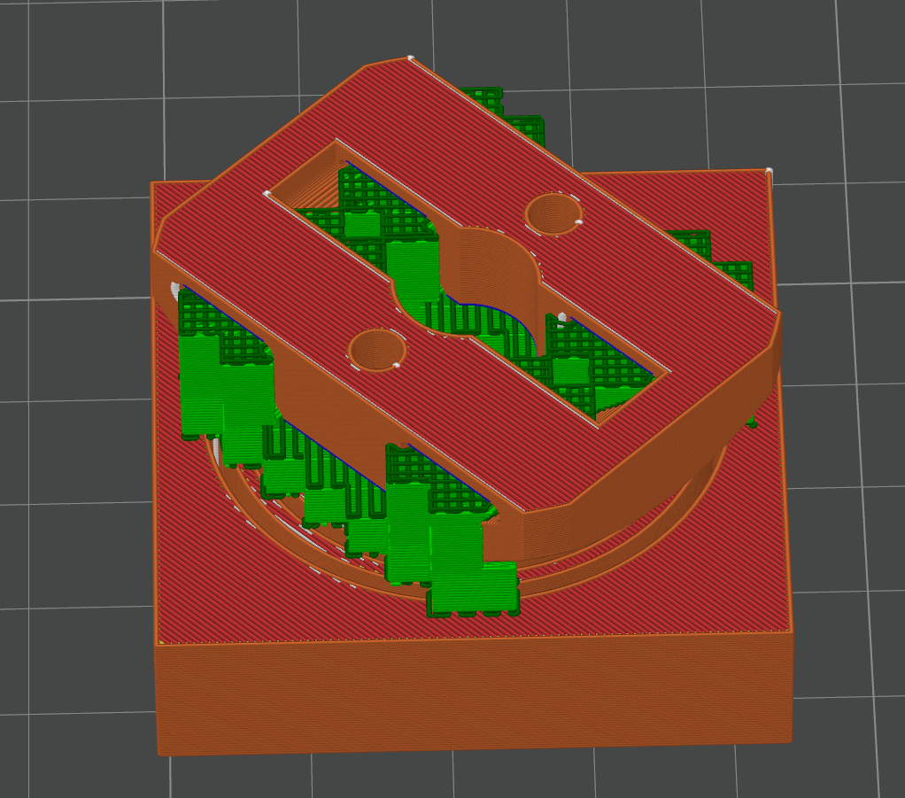
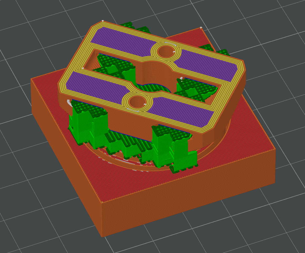
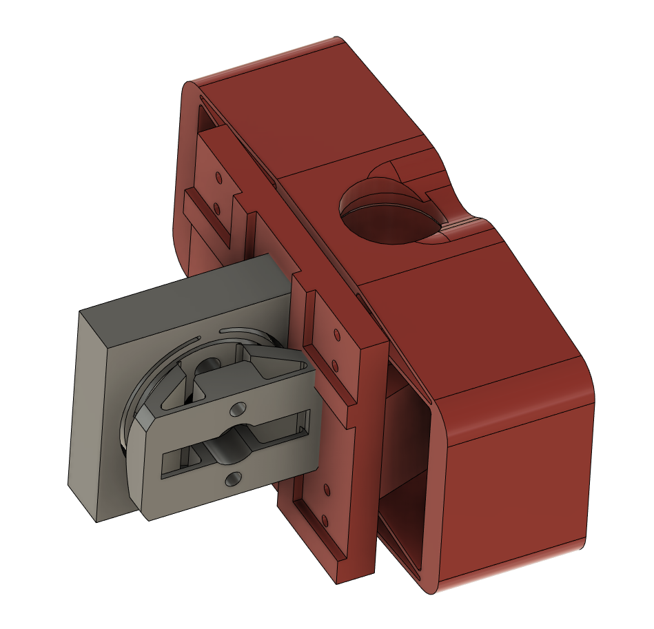 Given flexure directions and assembly challenges, this part will bolt onto the back of the Z-axis using a few bolts from the front and maybe with some locating features. That helps with eventual Y-axis design too, of course, since I can re-use the part on the bottom of the machine!
 Other unrelated minor update: I ordered a pile of 40x40 ENIG-coated FR4 coupons.
Discussions
Become a Hackaday.io Member
Create an account to leave a comment. Already have an account? Log In.