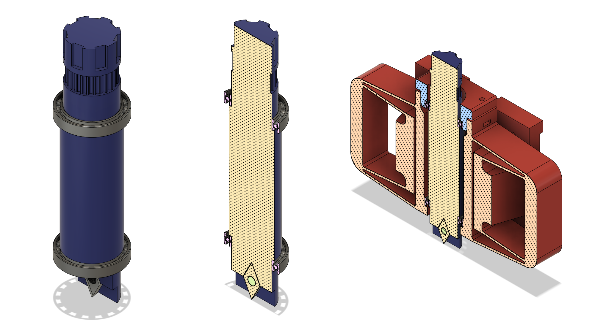
There are conflicting forces pushing me towards different print orientations on a few parts. The rotating part that holds the carbide insert which I call "tool-holder" is located using two 17x23 mm bearings which fit on either end, sitting on ledges:

I've gotten used to naively designing 3D printed parts to "just work", since nominal printing often yields a slight interference fit against precision metal parts and many things I do don't require a great deal of precision. Here, I'm relying on the bearing sitting perfectly against the ledges on the tool holder. Even though this isn't a high-speed rotary spindle, I don't want the bearings and mount to have to deal with a lot of angular misalignment. Ideally I would print the entire thing upright, so the critical round part of the tool holder that fits in the bearing is as accurate as possible. However, I'd also like to print the part with the layer lines orthogonal to the main cutting force, meaning flat on the bed with a bit of support material. Every time I ignore the anisotropy inherent to fused filament fabrication it bites me! Not to mention the Z-axis itself, of course; the flexures really have to be printed flat, meaning the internal bearing surfaces span layers and require support material as well.
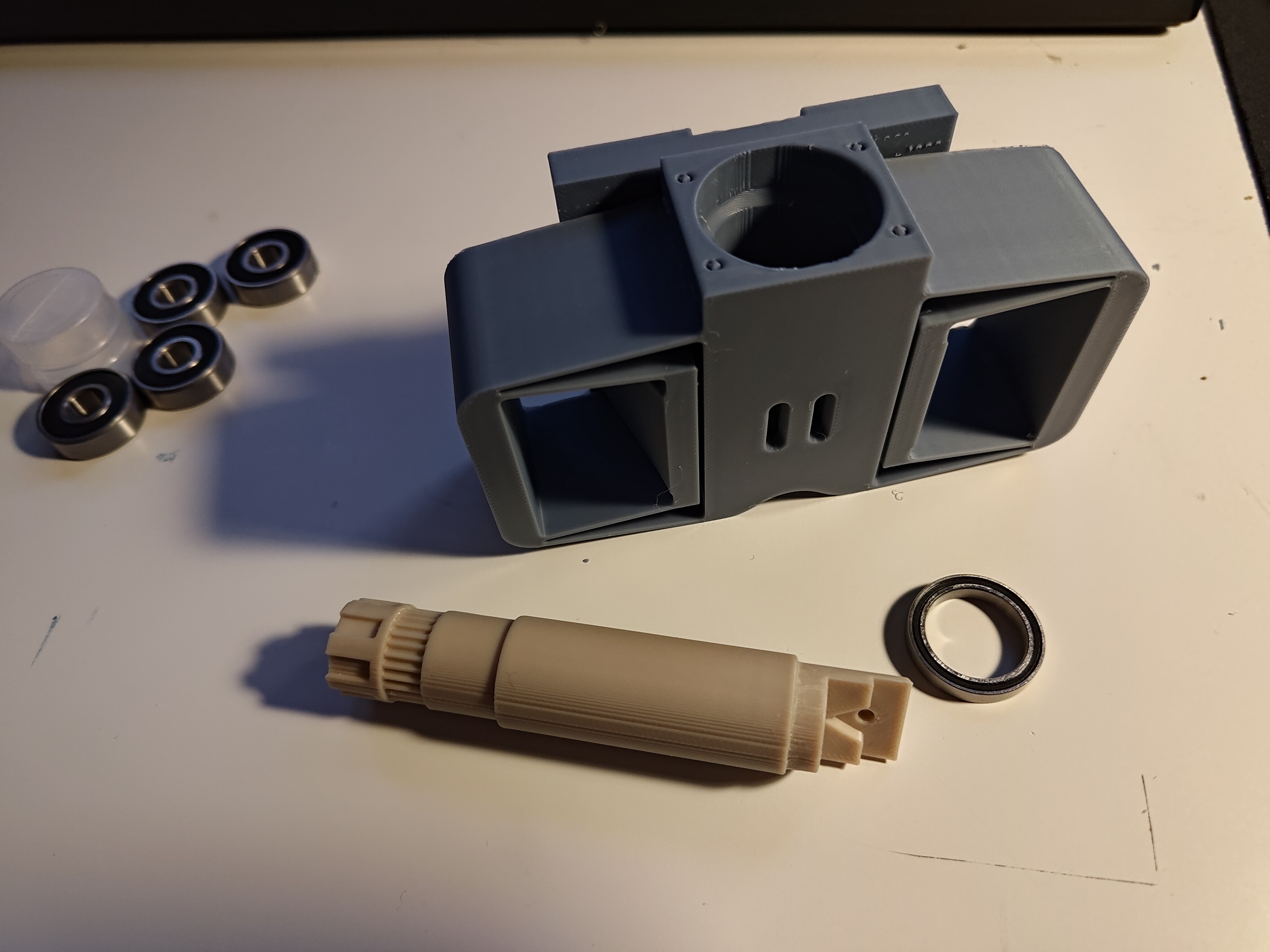
I have access to equipment that could true up the bearing races pretty easily, but I really want to keep this project as simple as possible fabrication-wise; requiring builders to post-process the parts off their commodity 3D printers using a big mill isn't great for apartment dwellers or smaller fab labs. So once the bearings showed up (along with a few extras, so I could be a bit forceful assembling one or two), I printed the parts shown above:

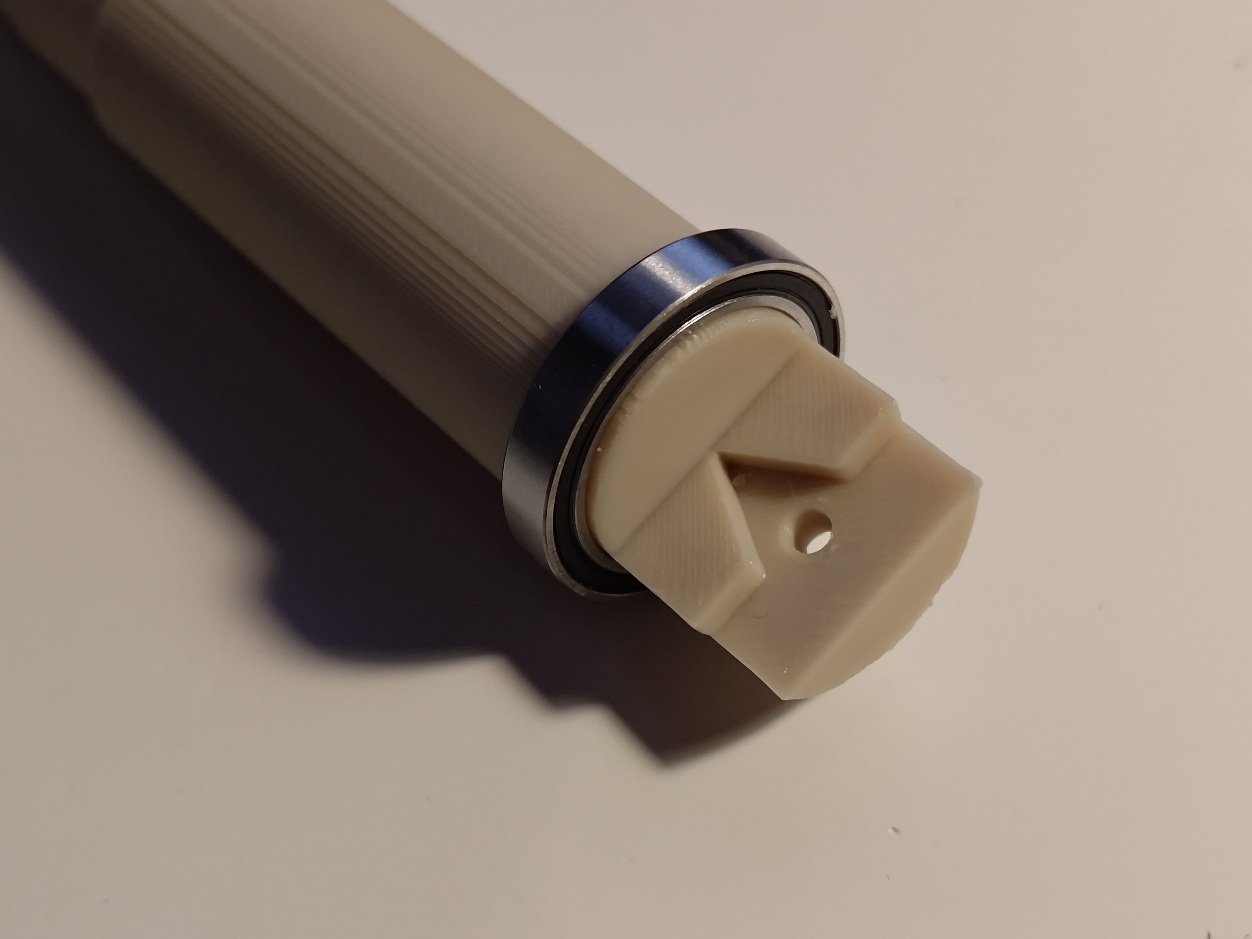
Round parts are usually a bit big when printed in this orientation to nominal size because of the irregular printed edge, particularly where the support material sits. After playing around with the tool holder a bit a clear update beyond this came out, too: the hand knob and area below the GT2 teeth doesn't neck down at all, so the bearing gets stuck pretty much immediately. On the tool side, I was able to trim the excess material off enough to seat the bearing without too much force:

I tried inserting the bearing and tool holder into the Z-axis print but the fit was too tight, and I didn't want to immediately destroy one of my new bearings (even though they were pretty cheap). I don't have easy access to the mount for the inner bearing, certainly not good enough to trim it with simple hand tools.
I held the bearing flat to the table and the tool holder by hand. I didn't visually notice any angular misalignment, but it could be sitting at a few degrees and I would probably not notice. A better metrology setup, even by just clamping the bearing down and measuring the displacement of the end of the tool holder, would go a long way.
Fixing this perfectly is another rabbit hole. Assembly precision past 3D printer capabilities could be important, but my intuition says it's not, at least versus the essential goals of the machine: demonstrate PCB carving with combined X/Y/R motion. As long as the rotary axis is stiff, angular misalignment up to a point will probably just cause premature wear and maybe a bit of heating for longer runs. I think the right move is to run a few off-axis print tests to determine the right over/undersize (depending on which part I'm trying to fit) for a nice press-fit with minimal post-processing. It may be the case that a good bit of angular misalignment comes from inconsistent round inner corners where the bearing sits, which I could avoid with a tiny corner relief dogbone of some sort.
 zakqwy
Discussions
Become a Hackaday.io Member
Create an account to leave a comment. Already have an account? Log In.