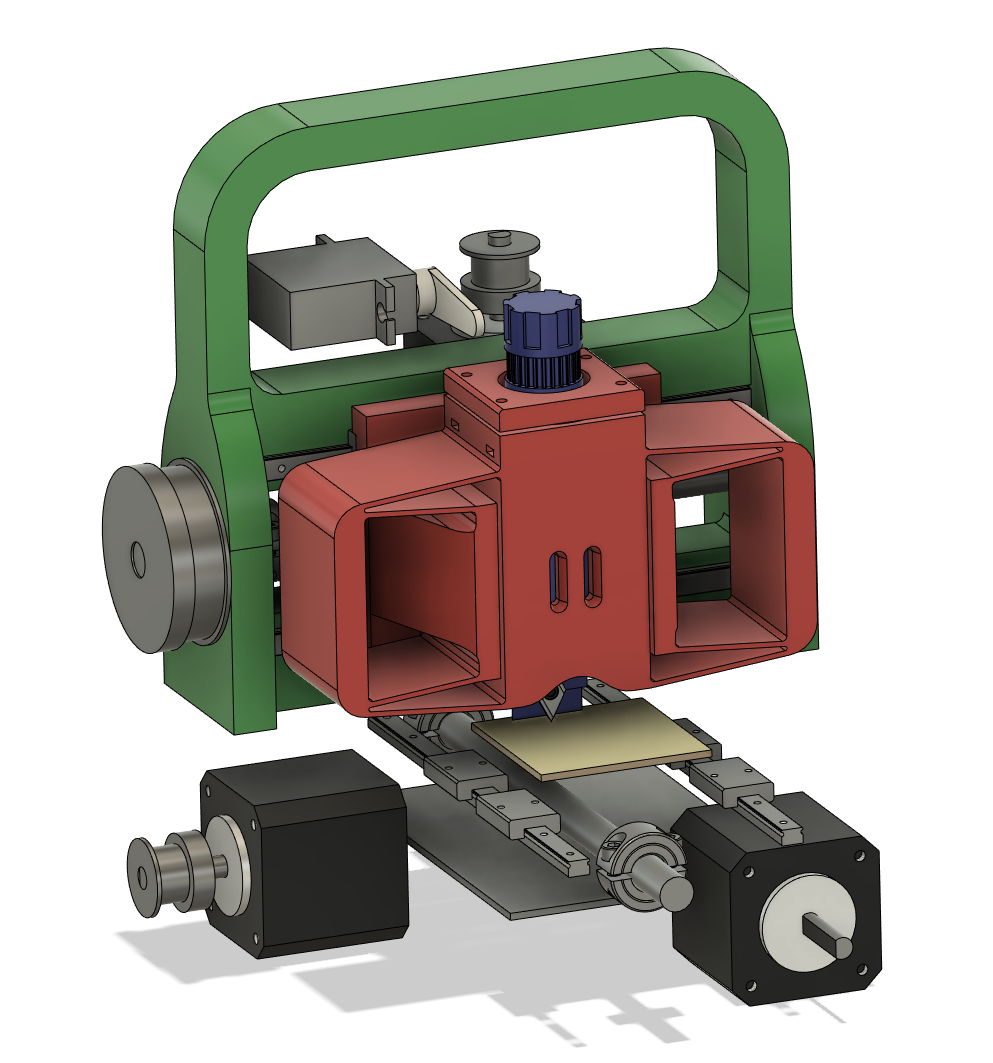
Maybe the gantry has a cute lil handle?
 Sans microstepping, the 2-mm-lead lead screw yields (2 / 200) = 0.01 mm resolution for a typical 1.8 degree stepper. So the 60-tooth gear on the lead screw really isn't needed given the feature size I'm trying to hit, but here it is; I might grab a few different belts and gears and experiment with different ratios. The large gear hides a 608 bearing press-fit into a flanged hole. I haven't added the opposite side support bearing which will get some sort of flexural overconstraint relief.
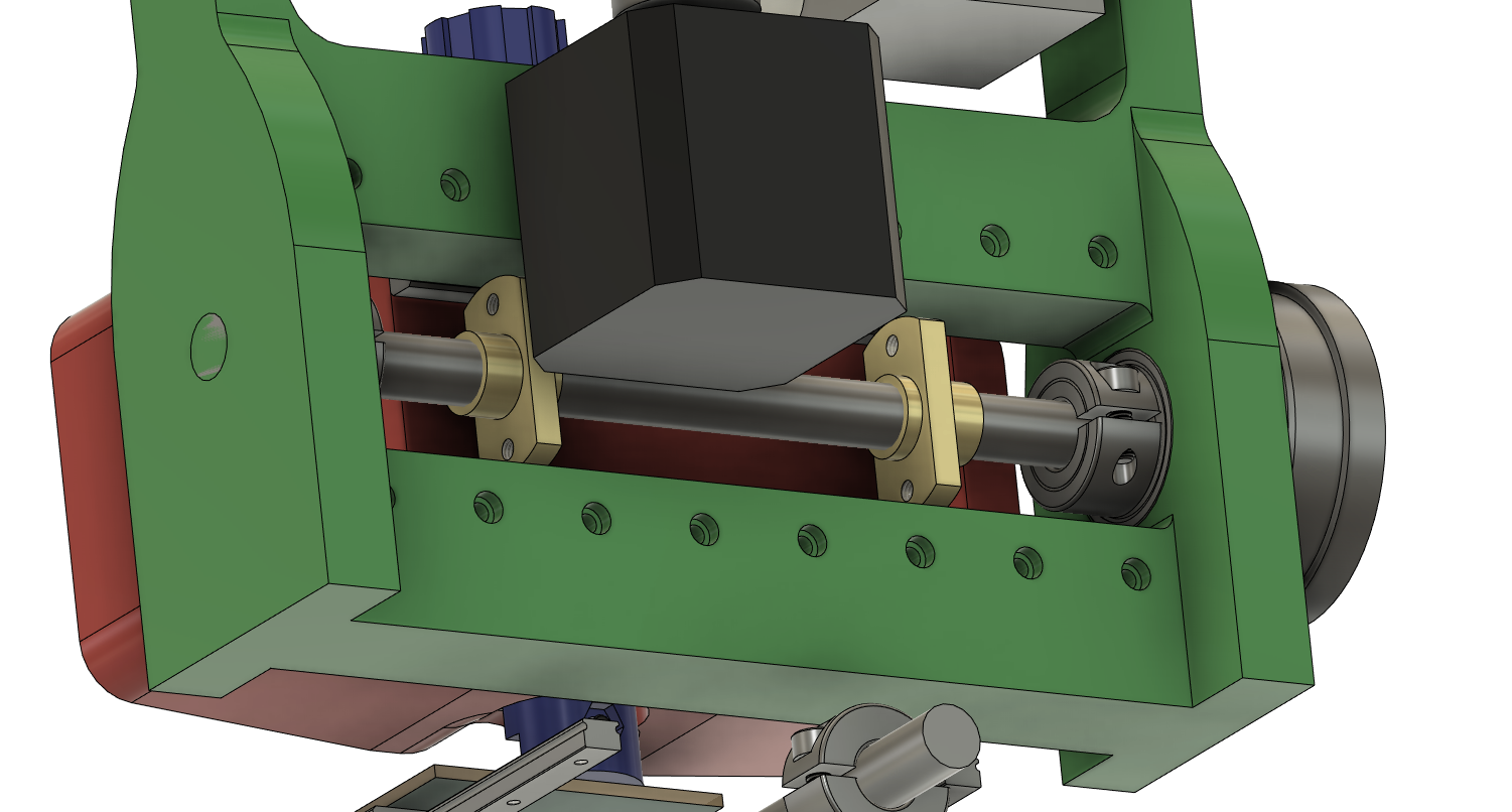
  The spring-loaded anti-backlash lead screw nut became two much smaller 2-bolt lead screw nuts with tapped M3 mounting holes. One will mount to the Z-axis with a bit of radial compliance, while the other will get this plus an adjustable axial preload. I picked up some lithium grease for the lead screws, along with a light PTFE-based oil for the linear guides. The image above also shows the row of countersunk holes for M2 socket head cap screws. The rails are 4 mm high and tapped through, so I'll allow for 3 mm of screw engagement from behind; as such, the main gantry is 13 mm wide to accommodate 16 mm screws.
 The bottom of the gantry will probably bolt to the base plate with beefy screws, and may have some alignment features as well. I'll want to include at least a bit of adjustment here so I can tram the axes square to each other with the test indicator. Up next, I want to finish the Z-axis; I think it will get a growth that extends back to the lead screw nuts, and then a removable piece that connects to the top and the lead screw nut extension (forming a loop over the top rail) which carries the servo and stepper motors. I'm going to sketch some ideas for the Z-axis tensioning system but may make this bit removable too, so it's easy to play around with different flexures and such.
 zakqwy
Discussions
Become a Hackaday.io Member
Create an account to leave a comment. Already have an account? Log In.