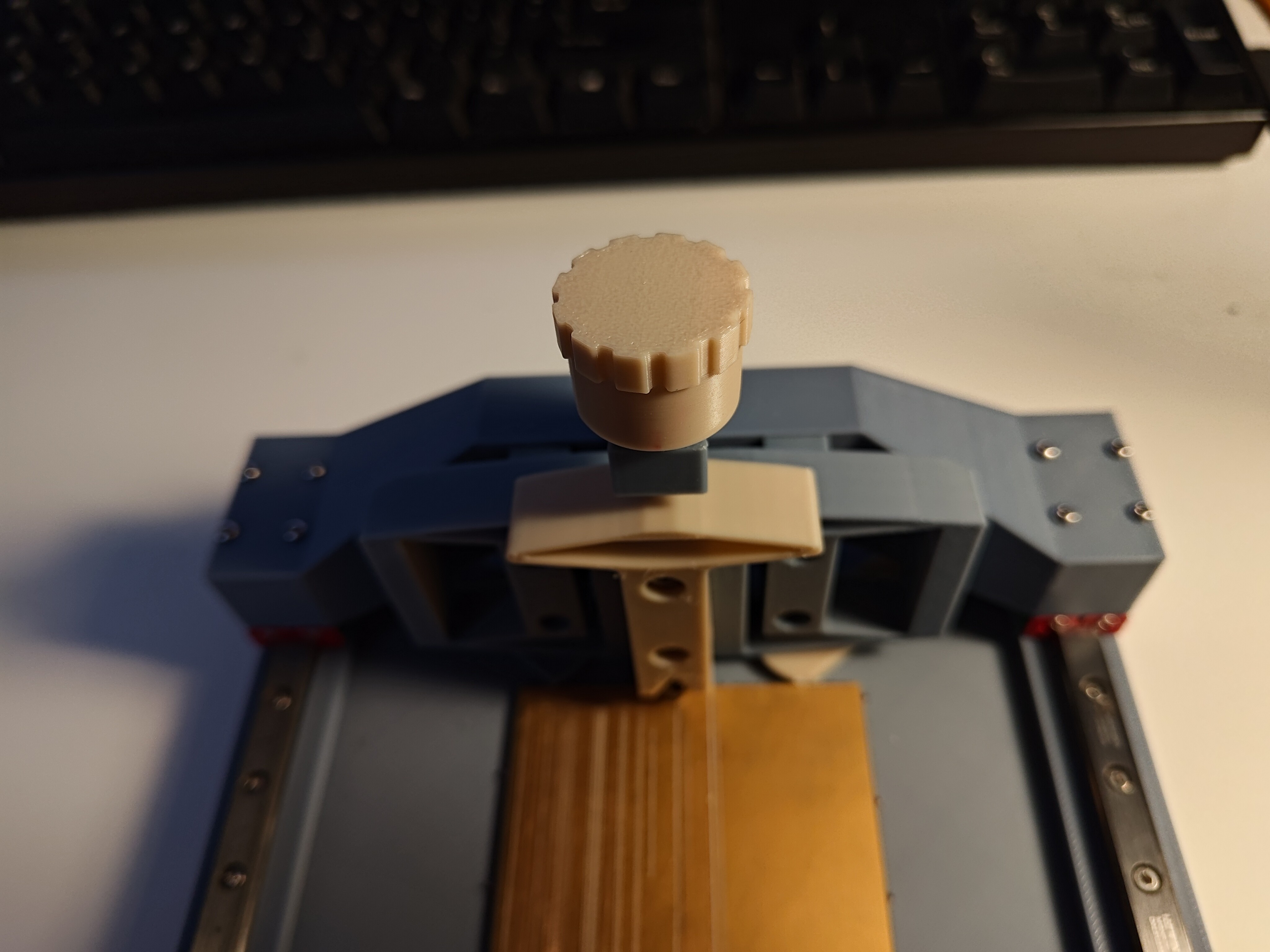
I added a little knob to the top of the test jig's adjustment screw, so I could keep track of rotations:

I also made a new clamp that bites a tiny bit more and has a longer arm. At some point I stopped changing my spools after printing other things in bone white, so there are now three such parts on the test rig. I suppose this helps me keep track of iterations!
I loaded up a bit of ENIG-coated FR4 and hand-tightened the loading screw until it touched the top of the flexure. I then advanced it one full turn and pulled a few test trenches; some of them weren't open fully, so I turned the screw another half-turn. That makes 540 degrees total, which for a 0.5 mm pitch M3 bolt is 0.75 mm. Note that this is just compression of the top springy flexure, of course, not Z-axis displacement!
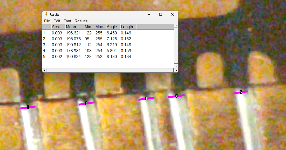
I pulled five more trenches at the same pressure setting, using my thumb to manually lift the Z-axis up on up-strokes. I used the same 0.5 mm QFN measurement method as before to estimate the trench widths using ImageJ, this time with the chip standing up on its side so the reference would be as close to the measurement point as possible:

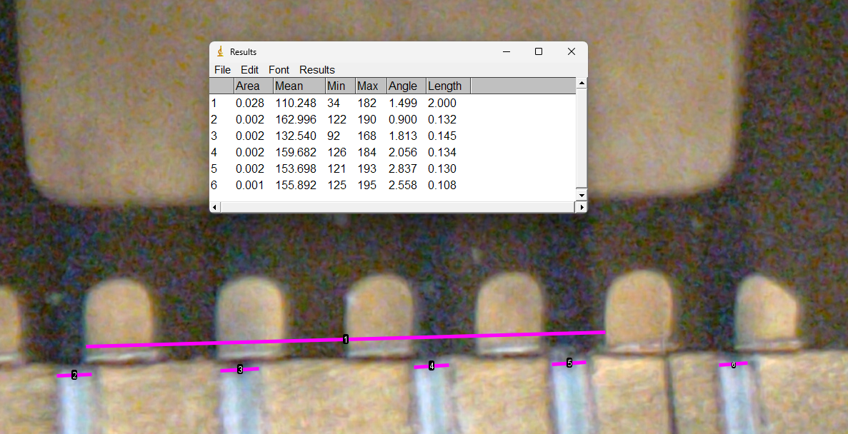
Perhaps call that 0.14 +/- 0.02 mm, noting that I'm at the limit of reasonable optical metrology with my current setup (a 10x hand loupe and a cell phone camera). It is definitely time to use a microscope with a calibration slide. I think the magenta bars above are reasonably well-placed, but the measurement for trench 5 in particular is questionable due to the poor photo quality. But that is still a great result: < 6 mil spaces! I split the different for another test by backing the knob off by a quarter turn, for ~0.63 of flexure top displacement:

A slightly better photo with more not great measurements, but perhaps encouraging results. It's a judgement call where the trenches start and end in the picture because there is definitely distortion of material on either side of the actual cut line which reflects light in weird ways. This set is definitely smaller which tracks since I dropped the pressure a bit, but I don't think I can really quantify the improvement or consistency yet.
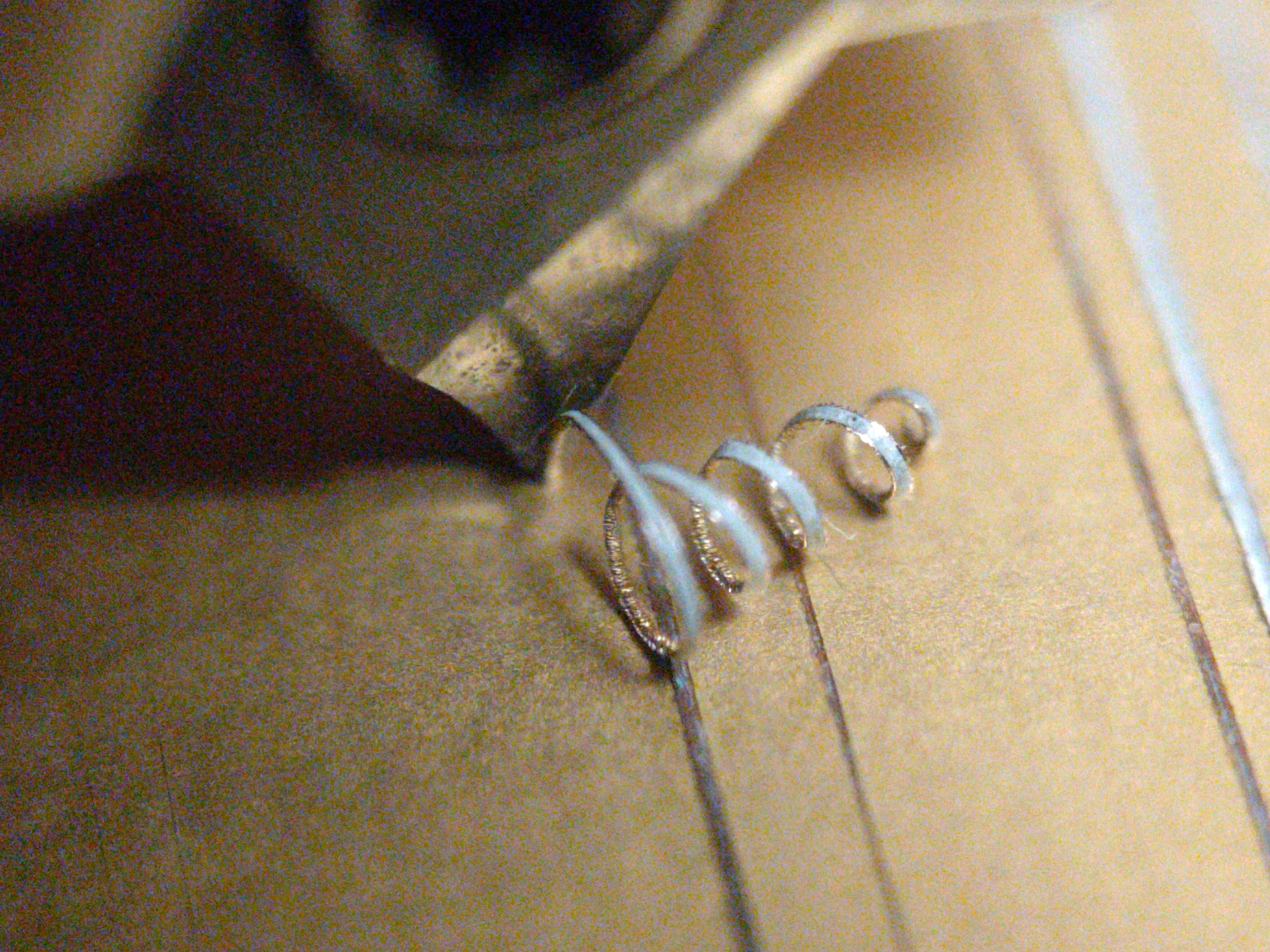
I also got some nice close-ups (well, not really nice, note noise and poor depth of field) of a ~0.15 mm chip being produced during the first test:

Pressure control! Like a record, where the grooves are perhaps 25 μm deep and the pickups resolve high fidelity micron-scale data, but the disk itself might have a fraction of a millimeter of warp. Record players use precisely weighted tonearms to ride the waves and discern the ripples. Is that the best strategy for this machine, since I care more about trench size than cut surface finish?
I'd like to revisit depth-based control by using a fixed cutter once I can automate axes, but the early tests really suggested that I got better results by allowing for compliance in the vertical axis. But this means the cuts feel somewhat uncontrolled: for example, I've noticed that when a cut doesn't quite make it through the copper I can re-run the gantry another time and sometimes hit fiberglass. Each pass produces a fresh chip from deeper in the PCB, and since the triangular cutter profile means depth controls width, I need to watch how depth changes as the machine runs. There is definitely an interesting rabbit hole here: how stiff does the Z-axis need to be? Do I start to run into chatter and resonance issues at lower feed rates if it's too compliant? Can I rely on the spring-back of the Z-axis flexure itself, or do I need to pull the cutter back after cuts? How much can the pressure vary with displacement vs the typical variability of FR4? Do I need to go as far as using a real constant force spring or a weight, rather than a simple flexure? Is none of this a big deal, since I can just take every cut once? How much does cut geometry depend on the cutter's grind, and how the sharp carbide dulls over time?
This does inform machine design, at least to a point. With the current Z-axis loading flexure configuration and stiffness, I saw a significant change when I advanced the loading screw by <100 um. The cheap-o "Power HD LF-13MG" servos I bought on eBay don't have an advertised deadband, but an ambitious value might be 1 μs with 0.1 μs/deg travel. Since I'm swinging the servo back up between cuts I'll easily exceed this, so it might be reasonable (or perhaps ambitious) to suggest I can hit +/- 1 degree accuracy with each stroke. With a 30 mm horn, that gives me around +/- 0.5 mm control of the end of the arm, roughly four times the difference in pressure between the first and second tests above. When the servo arrives I'll test it for repeatability, but a result like that would mean I need to reduce Z-axis stiffness significantly so the servo displacement has less of an affect on pressure, or include some kind of mechanical reduction linkage. Or I could keep using a screw with a servo, or change the servo out for a stepper motor, or hand-set the pressure and just use the servo to lift the carriage against the preload flexure as I did in these tests, or...
 zakqwy
Discussions
Become a Hackaday.io Member
Create an account to leave a comment. Already have an account? Log In.