 zakqwy
I think it is time to build a little machine. I want to test combined axis movement and see if I can build a machine stiff enough to perform well, using off-the-shelf motion components and 3D printed parts of various sorts. Generally, the machine should be:
- something I can build quickly, so I can make adjustments and spin another iteration before the conference
- not too expensive, so avoiding Misumi and Mcmaster in favor of eBay
- sufficient to fabricate a circuit board, so it should have sufficient axes and range
- an evolution of the test rig I built to test the cutting stroke
Keeping everything small and stocky will make the machine as stiff as possible given its PLA-based construction. I started by sourcing a set of linear rails; after perusing eBay for a bit, I found a set of four surplus Hiwin MGN5-series rails with four blocks each for substantially less than I paid last time. The rails are 110 mm long and 5 vs 7 mm wide, but I think that is okay; I made some rough guesses using an online linear axis sizing tool (I think it was Misumi's) and even with multi-kg loads it seemed like a 5 mm linear guide was more than sufficient. I imported the cutting tool into a new model and created a 40 x 40 mm square PCB target, then started composing bits and pieces outward from there. At this point everything is very much in flux and judged by eye; sizes and shapes of things tend to be driven more by what's available in commodity-machine-components-land rather than any sort of real engineering rigor. I try to keep an eye on the kinematic loop diameter, but cantilevers inevitably get balanced against 3D printed part thickness. Here's where a lot of the parts landed after a few rounds of iteration:
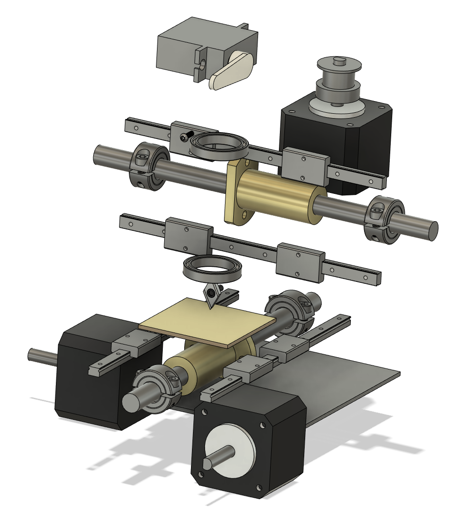 So stocky! I settled on MGN5 5mm-width linear guides; 8 mm lead screws with spring-loaded anti-backlash brass nuts; NEMA 14 stepper motors; 23 mm OD / 17 MM ID thin section bearings for the tool holder; and GT2 belts connecting motors to actuators. One midrange length NEMA 14 I found produces a holding torque of 11 N*cm, which given estimates about efficiency, friction coefficient, whether I want to drive the servos at their holding torque, etc. suggests I should be able to comfortably hit a few kg of cutting force (using T = F * (L / 2 * pi * e), where T is torque, F is axial force, L is pitch, and e is efficiency). So, uh, a few kg seems like it should suffice for a test, given I threw rickety scaffolding over the metrology rabbit hole.
 Like the test jig, this machine will have a flexural Z axis, although this time actuated by a servo through a flexure. The machine is a "bed-slinger" type, with the Y axis mounted to the base and the X axis hung from a bridge gantry. The gantry carriage then carries the Z axis flexure, which in turn carries the rotational (R? A? Probably R) axis spindle. The carriage has to carry the R-axis stepper motor, but I think the belt should be long enough that the motor can be on the other side of the flexure. I suppose tensioning it properly will be an important part of reducing off-axis distortion and actuation force required for the Z-axis. Overall, the machine fits nearly perfectly in a 150 x 150 x 150 mm cube; this will probably grow out a bit when I add manual axis knobs to X and Y, and the spindle keeps growing as I remember to add things, so the height might climb up a bit too. Still should be compact enough for my shoulder bag.
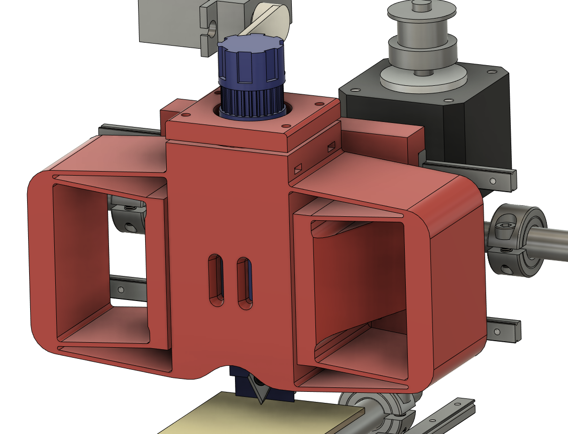 I also made some progress on the Z-axis and spindle, which really need to be designed in tandem with each other. A cutaway at roughly the halfway point shows the tool, bearing stack, bearing retainer, etc:
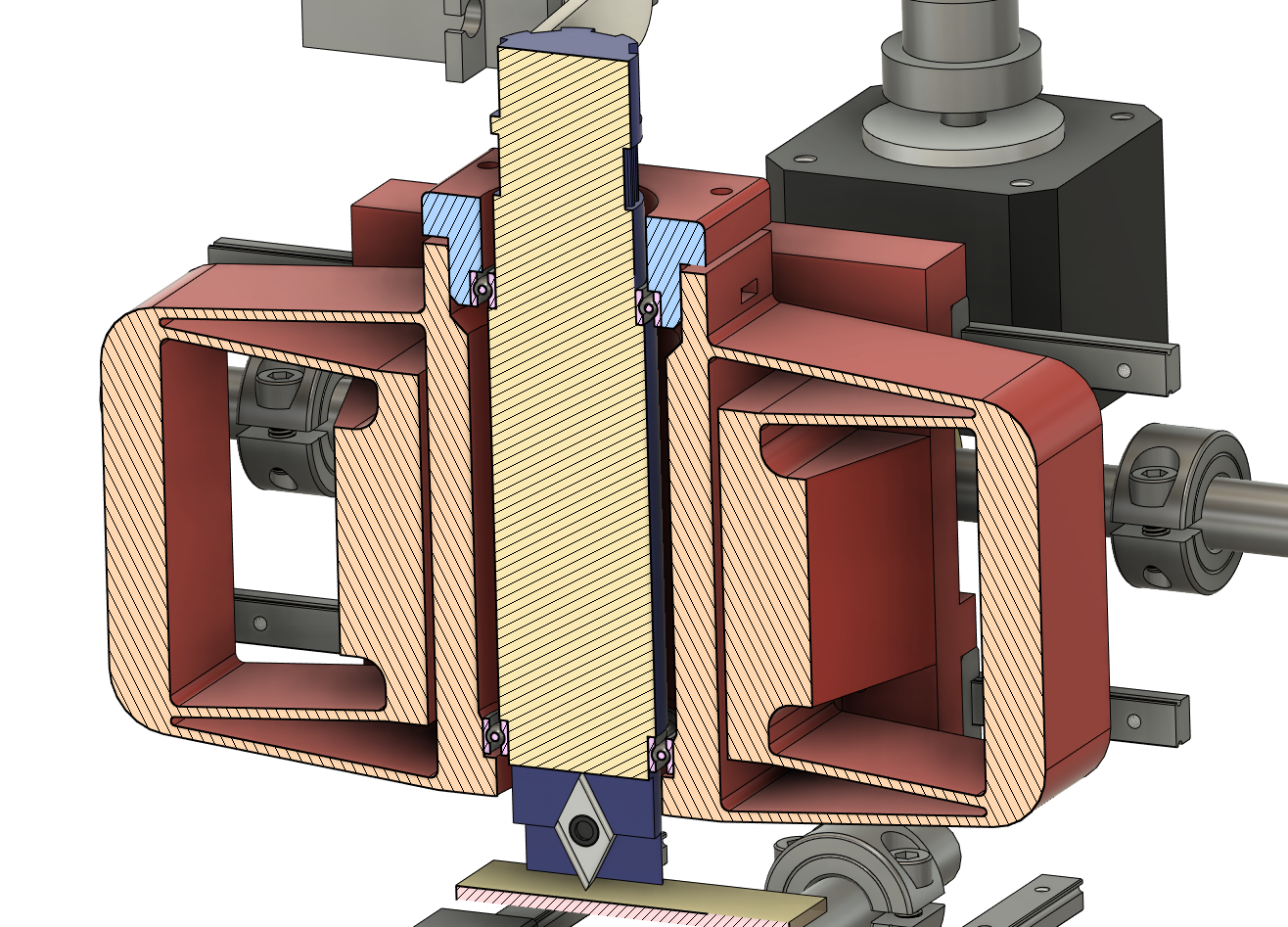 I'm probably over-thinking this a bit, but I wanted to properly pre-load the bearings, and the long distance between them should really help with the stiffness of the spindle. What's the expression -- anyone can design a bridge, but it takes an engineer to design a bridge that barely won't fall down? I'm very much in the former category here, pretty much adding material and reducing moment arms wherever possible to maximize stiffness. In any case, the top bearing is aligned with a cap that fits snugly in the flexure, and then preloaded with four M2 screws. Maybe I'll even include belleville washers!
 The tool holder, which is blue in the image above, holds the cutter rigidly without any means to adjust for concentricity errors. This is one of those things that could be addressed with a few flexures and microadjusters, but that would reduce stiffness and add complexity and cost; or I could shim the tool after installation if a test rotation shows a circle instead of a dot. Or I could just not worry about it, and if it's way off, fix it in the model and re-print. The holder also has an integrated 25-tooth GT2 gear (since that's the largest that could fit through the bearings) along with a little knurled-ish hand knob. I think one of the bigger challenges will be printing, actually; I'd like to print the spindle on its side so layer lines aren't parallel to the cut direction, but that might make the GT2 teeth not great and bearing concentricity will likely suffer. Again! Things to deal with in the future if they end up being problems, probably by splitting the assembly into parts that can be printed in different orientations (looking at you, gear, who wants to be printed flat on the bed) and then assembled.
The flexure kinda looks like a grasshopper. I added a little relief at the bottom so the tool is easier to see and change, and included a pair of nostrils, so I can add patterned tape to the tool holder and see it rotate. Flexure sizing is very much eyeballed, but the ratios are about right given the displacement needed and my desire to maximize stiffness vs off-axis loads. This part might get printed face down on the bed with support material between the flexure and the carriage mounting plate; this keeps layer lines out of the flexure beams and lets the linear guide block locating features be printed last, without support material. I still need to hang the Z-axis servo and R-axis stepper on the back of the carriage, and tie it in with the lead screw nut, but I might make all of that happen via a separate removable block. That will help a lot with printing and assembly, and the compliance I add to the lead screw nut mount should take up any misalignment resulting from the assembly method. Also I'll probably add some locating features. Maybe a cone or two.
Discussions
Become a Hackaday.io Member
Create an account to leave a comment. Already have an account? Log In.