Okay! I am on the hook to build a little machine. Time to study the cutting process a tiny bit more; at bare minimum, I should understand the magnitude of the forces involved so I can properly size actuators. Right?
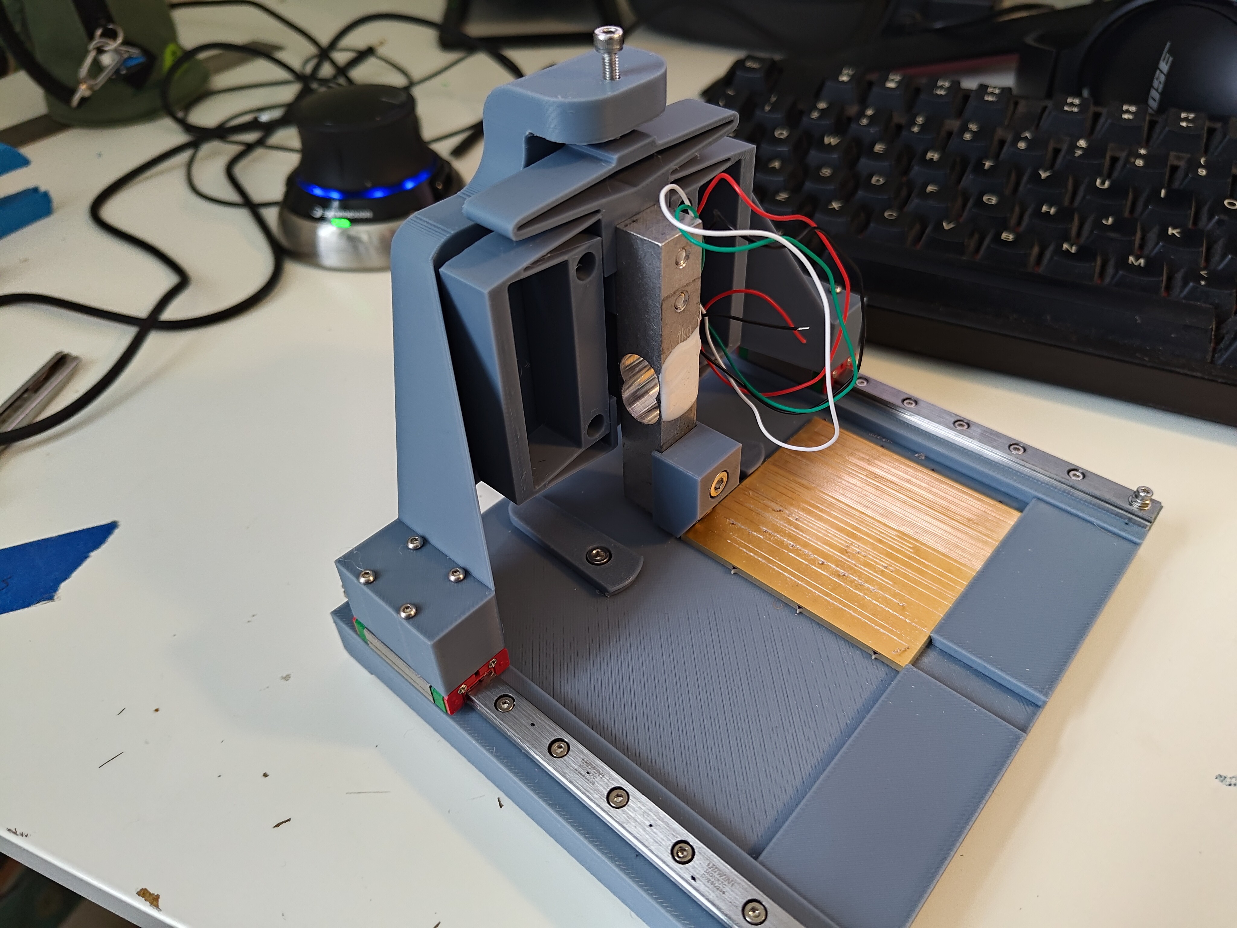
I sourced some cheap 1- and 5-kg load cells and redesigned the gantry and downstream elements to accommodate the sensor in series with the cutter. This adds a pretty significant cantilever to the kinematic loop, but I thought I could get away with it... worth a try for data!

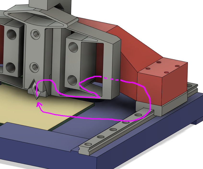
Here is the load path (well, it splits through the flexure, so this is the lowest load path) for the original test apparatus:

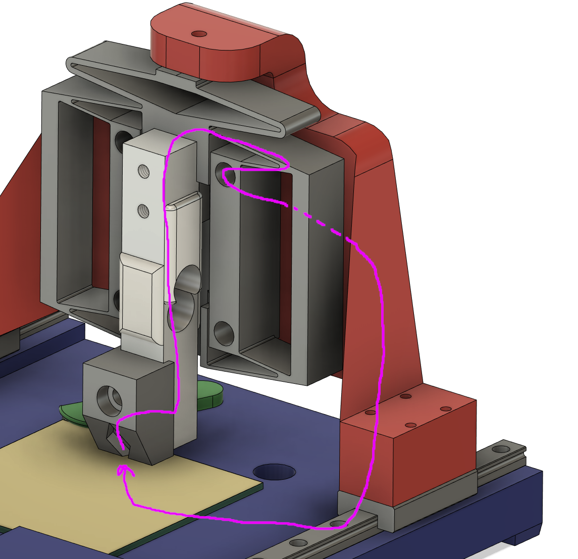
... and here it is for the load-cell-equipped version (again, split from the flexure, but tracing the top path since that's where the load cell connects):

So like... vastly less good. Lots of 3D printed parts holding long cantilevers. And the results bore this out; I wasn't able to get anything resembling a good cut and had a ton of chatter. The results looked a lot like the fixed cutter tests! I could see the cutter visibly rotate under the load, changing its rake angle as it skittered down the FR4. Rather than continuing to go down the metrology rabbit-hole (as fun as metrology rabbit-holes can be), I decided spec conservatively large motors and move forward with a sprint towards a multi-axis machine test. Good idea? We'll see!
 zakqwy
Discussions
Become a Hackaday.io Member
Create an account to leave a comment. Already have an account? Log In.