At some point over the summer of 2024, I got my hands on one of those modern 'input shaping' FDM 3D printers. I have great access to fabrication equipment at the day job, but I decided it was time to start firming up the line between work- and work-adjacent projects and stuff that is really just my own. My apartment is pretty small, but design constraints can drive creativity, and limiting the scope of the fabrication stack means work I eventually open-source is more accessible to a broader range of audiences.
It turns out having a speedier-than-I'm-used-to 3D printer sitting behind me results in a massive improvement in design iteration cycle time. I tend to make pretty small things using parametric feature modeling tools, and often a test design prints in 10 or 15 minutes! That is fast enough that I sometimes start designing assemblies that bolt or pin together and print the parts as I go, and the printer stays a step behind as I build out a given design. I've started to think of my printer as less of an overnight fabrication contractor and more of an on-call prototyping intern; I toss a part over the fence and start working on the next one, and by the time it's ready to print, the last bits are ready to bolt together. Wild.
So that was the context when the call for 2024 Supercon talks landed. I didn't think much about it; I knew I wanted to go to Supercon, having missed 2023 (my first miss of an in-person SC!) due to travel, but didn't think I had a worthwhile talk to give. I think it's important to leave room for new voices whenever possible, recalling the life-changing impact my first Supercon talk had on my journey through life. But then... of course, as always, the submission deadline was pushed back, and I realized that I might be able to squeeze in a sprint towards a real PCB carving experiment to validate the concept and paint the way towards a machine.
The experiment is simple: constrain the carving tool to a single linear axis parallel to a circuit board substrate and manually drag the cutting head through a cutting stroke, then visually examine the resulting trench and estimate the minimum attainable width. Given my experience holding the lathe inserts in a pair of locking pliers, it seemed that I'd likely need to vary the rake angle of the cutter to get a consistent result. I also wanted to test height- vs pressure-control; my instinct was that the latter would be best, since rigid height control would require the substrate to be flat within a few tens of microns. So I designed a simple test jig around a pair of tiny linear rails; following the aforementioned print-design workflow, this came together comfortably in a day or so:

Many things to consider here! First and foremost, stiff machines are almost universally better than floppy machines. Stiffness depends on both the form of the kinematic loop, which is the structural path connecting the cutting tool and the substrate, and the materials used for fabrication. A stiffer machine deflects less under cutting loads, resulting in more predicable performance, less chatter, higher acceleration capability, and a ton of other lovely perks. A floppy machine with a big cantilever on the Z axis may result in a gantry that twists too much under load, effectively changing the rake angle of the cutter.
But time is precious, and frankly, I'm not a great machine designer let alone mechanical engineer. Understanding the stiffness of a machine design is a critical part of creating a reliable and effective platform for performing useful work, but in this case, I just need to constrain the cutter well enough to justify the next iteration. I no longer have access to world-class FEA tools and the best thing for me to do is to carefully scaffold over tempting rabbit holes as I race towards the talk submission deadline. Because if I can show a good result here, I think that sufficiently de-risks the whole project enough to justify a submission and the ensuing machine-building sprint to Supercon.
I started this design by sourcing a pair of nice Hiwin linear rails from a reasonable-seeming but non-authorized distributor. I designed a base in Fusion360 (all of this work is in Fusion360, ugh) and mounted rails and blocks, then attached a 0.01 mm resolution test indicator to one using an articulated arm and a 3D printed adapter. I used this to sweep the opposing rail for parallelism; with both rails butted against 3D printed stops I showed around +/- 70 um of skew, but was able to tap the rail under test to within a fraction of a tick mark (< 10 um) of parallel. I tightened the bolts and tested again, and then a few weeks later after using the machine for many dozens of tests, and found that the alignment hadn't shifted. So far so good, at least for a no-load case!
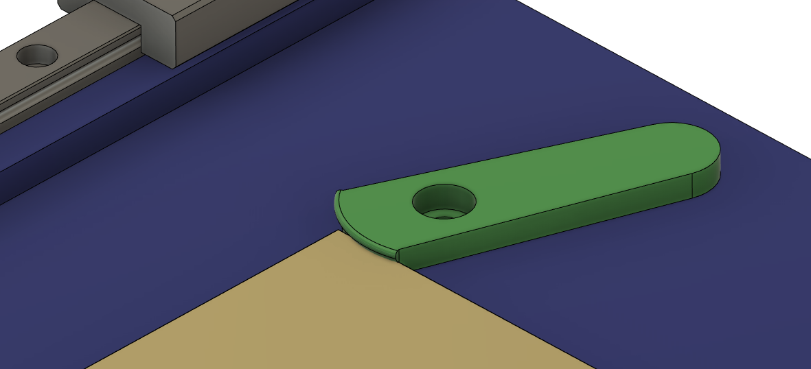
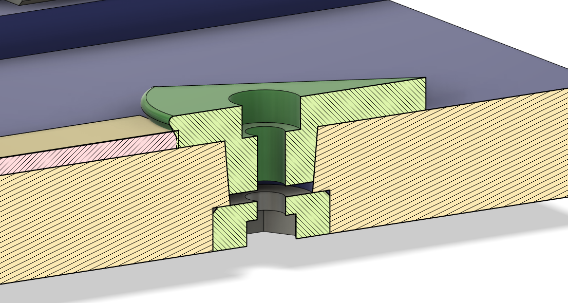
The design has a lot of interesting details, like a pair of logarithmic clamps to hold the 60x60 mm ENIG-coated FR4 panels:

I initially used a fixed tool holder with slots to mount to the gantry, and just pushed it into the material before securing; however, I found that the tool chattered a ton and generally produced inconsistent cuts, sometimes diving far too deep and sometimes skipping over the surface. This seemed consistent regardless of rake angle; however, rake angle is also a bit weird with this insert since it's got an angled chip breaker.

above on the right side of the coupon, mostly barf results using a fixed tool holder regardless of cutter angle. insert no longer mounted to holder.
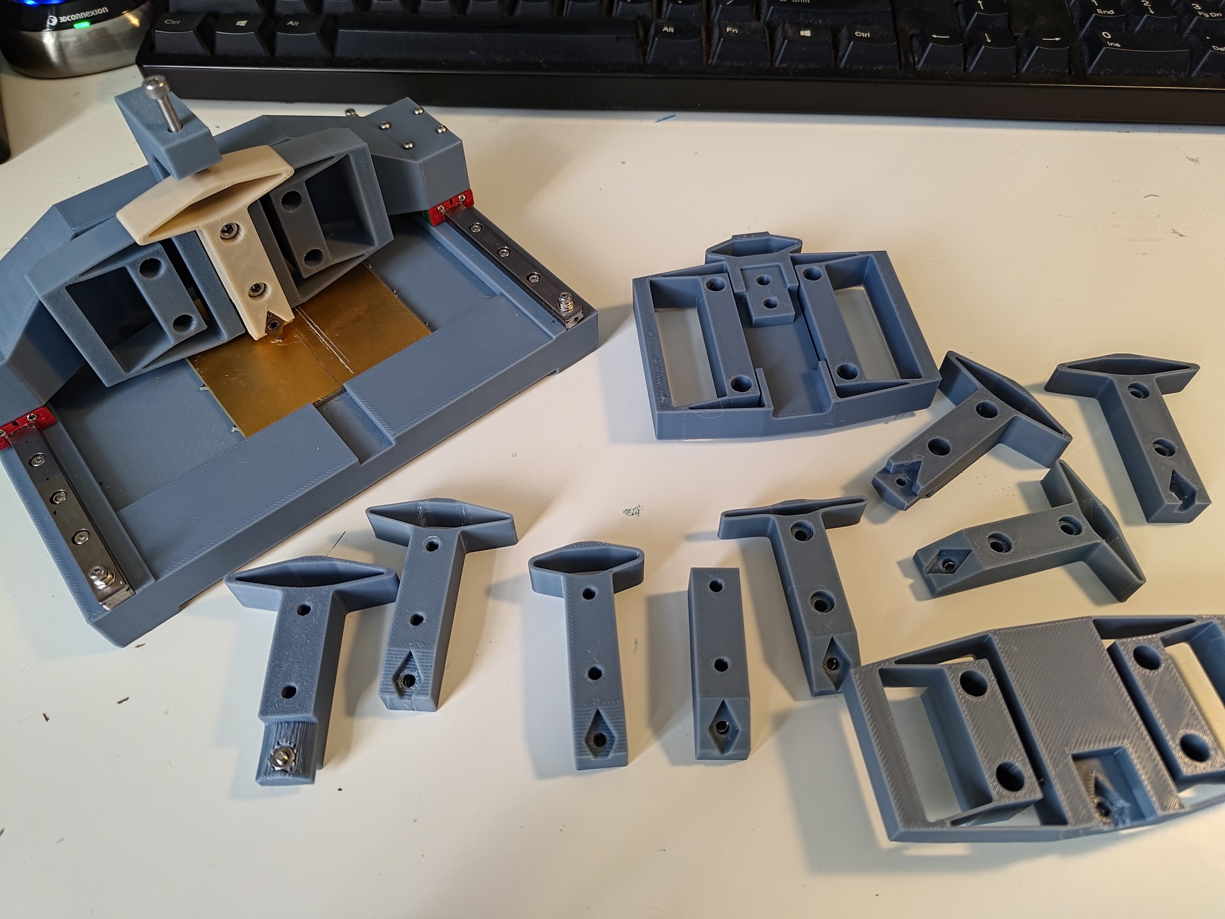
To add adjustable pressure to the tool, I added a small-displacement Z-axis to the gantry using a parallel beam flexure, which does a pretty good job of constraining the tool in all axes other than vertical. I included an additional flexure at the top for a screw to compress so I could adjust the pressure on the cutter.

above, a few flexural axes and a bunch of tool inserts with different angles and springiness, including a mounted one whose color I forgot to swap before printing.
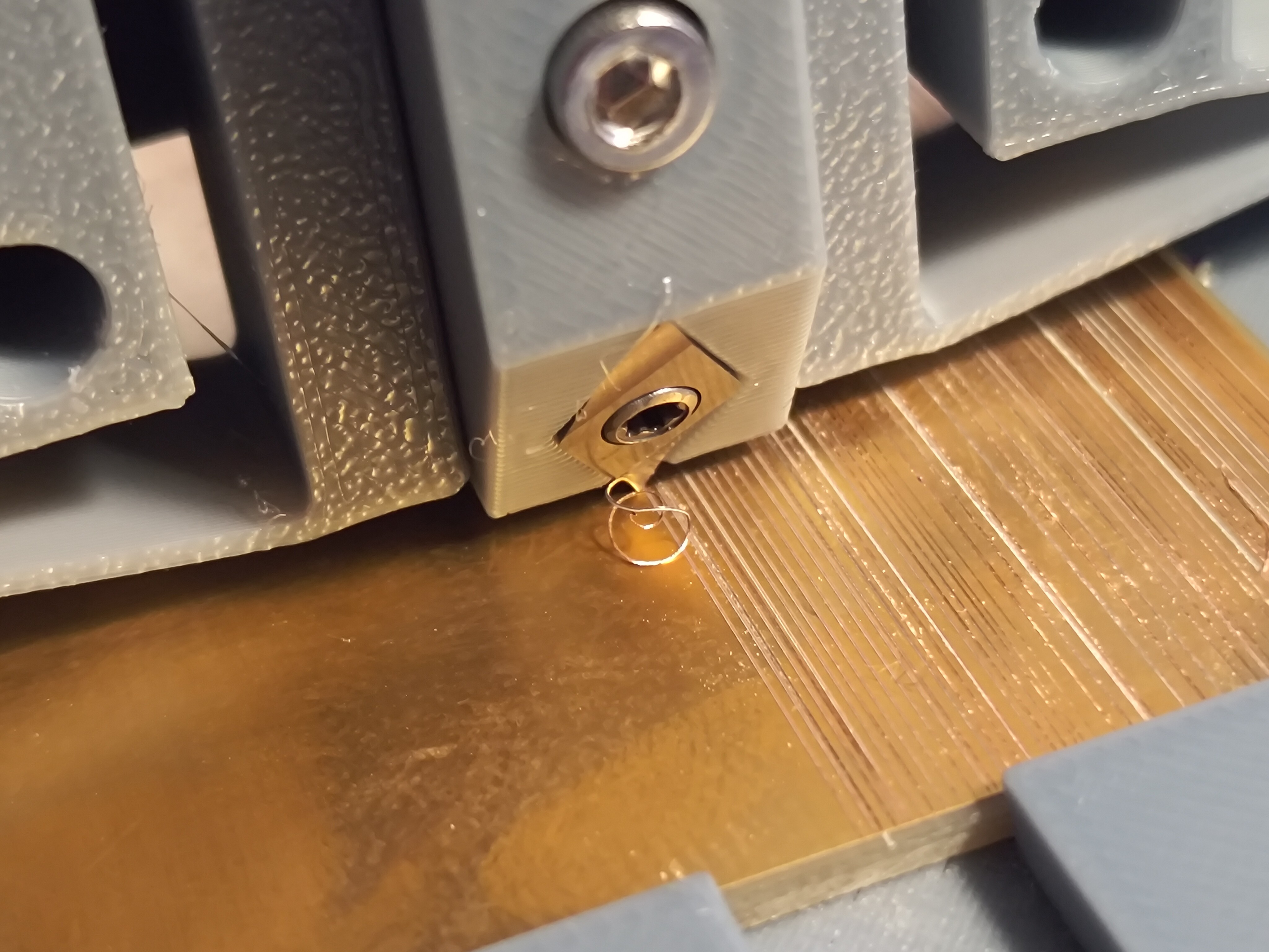
Rigor! Quantify cutting forces! Simulate flexures! Math! Do it right! Ah, but again, I'm impatient, and this isn't an engineering project; it's a sprint towards proof-of-concept, and sometimes it's funner and faster to just throw things at the wall and see what sticks. After a few experiments I managed to get some great (if a bit screechy) results:

Using a 0.5 mm QFN for scale and ImageJ, I estimate that I'm hitting 100 um (4 mil) spaces and traces using a gently sharpened cutter

... and that's where I got to around 10 PM on the night of the talk submission deadline! A worthwhile proof-of-concept for the core cutting mechanic, with a ton of unknowns and details to flesh out. I quickly mapped out a few months worth of ambitious machine-building plans and hit the submit button.
 zakqwy
Discussions
Become a Hackaday.io Member
Create an account to leave a comment. Already have an account? Log In.