The Circuit Graver is a project I have worked on, lightly at most times, for the past eight years or so. Around then I started prototyping a lot of circuits quickly, and needed a cheap, simple, high-performance method to mash parts together such that the resulting circuits would survive living in my bag. Perfboards, like the lovely Perma-Protos from Adafruit, fit the bill for gluing breakout boards together, but many of my projects end up needing certain physical characteristics early on: LEDs belong in specific spots, small form factors are nice, stuff needs close integration with existing parts, that sort of thing. I tend to build projects that are light on the code and heavy on the other bits.
Existing methods for fabricating circuits at home are quite advanced. Photoresist and etch can achieve quite fine detail using cheap printers and a reasonably small place to do messy work. Milling is a lot cleaner, quite reliable, and means you have a tiny CNC router to make other things, which is great. If you have a laser cutter with a 1064 nm source, you can laser engrave fantastic circuits once you dial in the cut parameters. And other methods, like those using conductive ink, seem to have come a long way too.
But! For my circumstances, none of those methods were really ideal. I only tried playing with ferric chloride when I was much younger, but the messiness really was a problem for me, or at least my parents and their reasonable wish to maintain a clean laundry tub. Milling machines have historically been too expensive for me to justify (and now, in the age of 3018s, too loud for my apartment); additionally, milling the really tiny features needed to access the most interesting parts in Digi-Key's catalog is quite difficult and delicate work. And never mind the cost of a milling machine next to a laser cutter! Instead, I started using a box cutter to trench long gaps blank copper-clad FR4, creating isolated conductive islands that I could then top with parts. Here are a few examples from early years: auto dice, simon suggests, phonetroller I, neuroscope. I also gave a talk on the method at Sketching in Hardware in 2017; you can find the slides for that here.
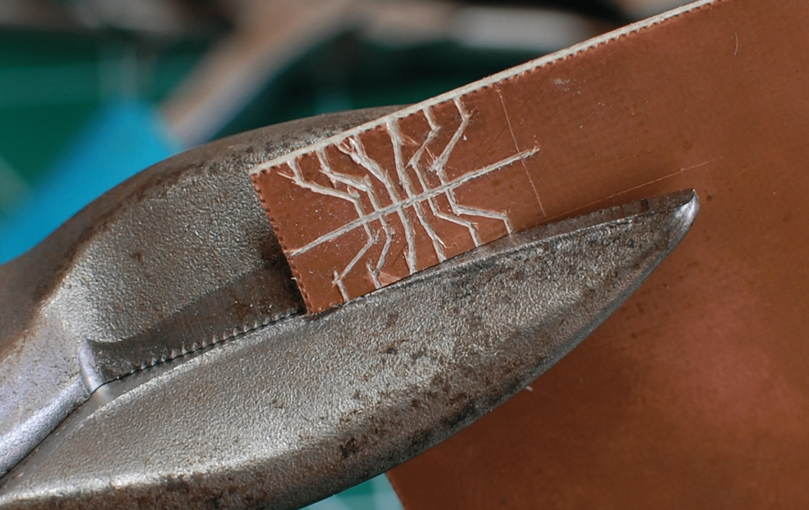 Later, I ended up as a grad student in a lab with plenty of interesting fabrication tools. I milled PCBs for classes, for fun projects, and for research, spending a great deal of time with a lovely Roland SRM-20 driven by mods. I generally used a 1/64" flat end mill, and limited my design rules to 0.5 mm (20 mil) spaces and traces. That usually meant SOICs, breakout boards, and 0805 and 1206 components, for which I made do, or just ordered lovely commercial boards and waited a week or two. Milling is a lot of fun, but it does have its drawbacks! Accessing smaller components and tighter design rules means using angled engraving bits or awful 0.01" end mills; it makes a ton of dust, so FR1 is a better choice if you don't have good dust management; most mills are a bit on the loud side for a home or shared workspace; and even simple boards often take half an hour or more to produce.
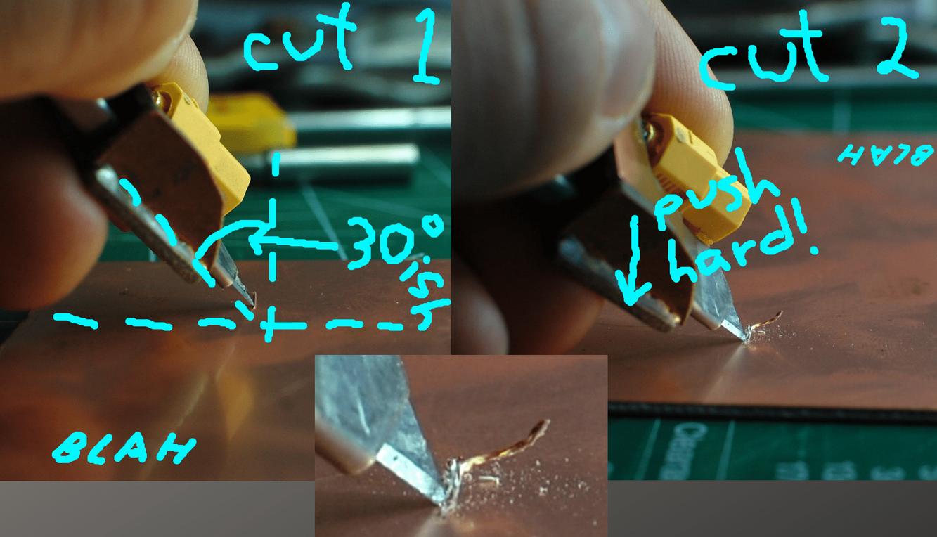
 Later still, I started mulling over whether the carving process could be automated. My normal method is to use a sharp Olfa box cutter, often with a custom-built (out of FR4, of course) finger rest, to cut a pair of angled slots next to each other, lifting up a nice V-shaped wedge of fiberglass and copper. The quality of the cuts varies a lot; FR4 is inconsistent so it is easy to gouge wider tracks, and complicated net outlines are often simply split into square-ish blocks that can later be joined together with fine magnet wire. Getting rid of the two-step knife cut seemed like a good idea; the amount of pressure needed is quite substantial, and blade wear is a real issue.
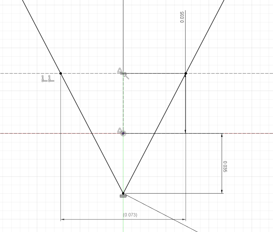
I found inspiration (and a project name) in gravers, the simple square-fronted tools that engravers push through metal to produce tiny precise grooves. Rather than using long steel graving blanks, I eventually found a super-sharp carbide lathe insert: the Mitsubishi BCET070201R-SRHTi10. I figured carbide would help with blade wear against fiberglass, and the 55 degree included angle and 0.1 mm tip radius seemed like a good starting point for experimentation. Given the ~35 um depth of a 1 oz copper pour, a minimum cut would yield a ~150 um (~6 mil) trench:
 Or, assuming I need a 1x overcut due to inconsistency of material and to reduce the chance of pushing the copper out of the way, perhaps a ~200 um (~8 mil) trench:
 That still seems worth pursuing; I've designed plenty of simple boards with modern QFN and 0402 parts with 8/8 design rules. And I could always sharpen the tip to a point with a diamond hone, which would probably make it more prone to chipping but could theoretically yield 75 um (3 mil) trenches:
Seems ambitious! But still -- shoot for 3/3 or 4/4, and if it lands at 6/6 or 8/8 it still expands the addressable part catalog by a mile.
So I bought a pack of inserts, held them with a set of locking pliers and dragged them across a bit of copper-clad a few dozen times, varying the angle and pressure as much as I could. Many of the cuts turned out quite poorly, with the insert catching periodically in the work and producing a ragged edge. However, I did find a sweet spot eventually, and managed to measure one ~125 um (~5 mil) trench. Huzzah!
I put the pack of inserts in my bag and carried it around for a few years.
 zakqwy
Discussions
Become a Hackaday.io Member
Create an account to leave a comment. Already have an account? Log In.