 zakqwy
I simplified the preload mechanism, noting that this doesn't include any accommodation for radial movement:
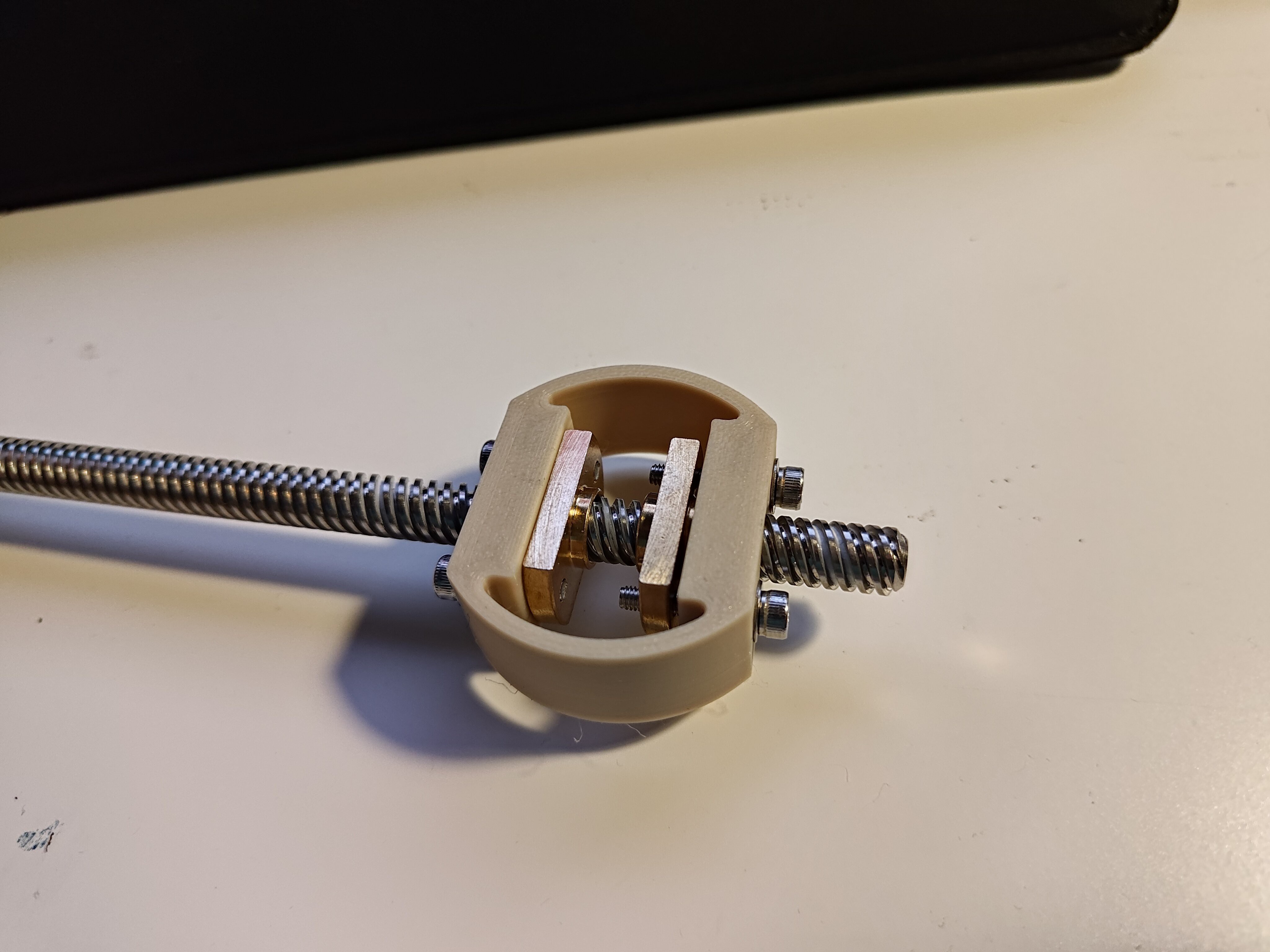 The two longer M3 screws put a lot of compressive force on the flexure, which has a thick 2.4 mm cross section and not a ton of length, so it's quite stiff. I got this nicely adjusted so it's fairly easy to turn by hand but impossible to push into backlash-land (or at least, the tiny movement isn't detectable like it was previously since I have to push so much harder). I think it might make sense to split the radial flexure mechanism between this part and a mating receiver on the Z-axis, since that would allow me to print both of those flexures in the preferred print orientation.
But! This machine is too small. Not by a huge amount, but a number of spaces I left to fill with "stuff" are just requiring too many sacrifices to avoid interference. I tried to do this to minimize lever arm length and maximize machine stiffness, but it's having all sorts of annoying follow-on effects. For example, there isn't enough room between the X-axis rails to fit the lead screw nuts, so they end up really far out anyway. Why not move the rails apart a few centimeters, and deal with the machine being a tiny bit taller?
Another place this pops up is in the spindle. Increasing its size slightly would allow me to use 6803 bearings rather than 6703s; same 17 mm ID, but increasing the OD (and corresponding space for balls and grooves) from 23 mm to 26 mm. I bet the axial loads I'm expecting would be okay with 6703s, especially just for testing, but why not bump it up a bit to a non-super-thing-section bearing?
I've also been printing test holders for the bearing, since the nominal 17 mm OD / 23 mm ID really didn't work given the spindle print orientation. It's nearly impossible to scrape out all of the support material in the base of the spindle, and even with it gone, the top layer is still a bit out of round. With a bit more space, I could split the spindle bearing mount and have a removable cap for installation! I'm less worried about the upper cap since I can just print it flat on the bed, since it doesn't have to integrate the print-direction-mandating Z-axis flexure. It's a bit easier to trim and sand the spindle down to size, so that will probably be okay for the ID parts. I guess this is why folks are interested in >3 axis printing.
Or, and maybe this is radical, but what about separating the spindle holder from the Z-axis entirely, so I can print the spindle holder upright? Ugh the bearings would fit so much better, and I could just bolt it together and include some locating features of some kind. Maybe the flexure could get split into left and right sides which just bolt through the spindle holder without requiring a thing wrapping around the back. This might call for some notebook sketching.
Discussions
Become a Hackaday.io Member
Create an account to leave a comment. Already have an account? Log In.