I'm worried that the machine isn't stiff enough! I don't know enough about the cutting forces to really judge this. The test jig seemed to work under hand actuation, but it did make screetchy noises sometimes when dragged quickly. I think the gantry was flexing and vibrating under load. But I was able to get great results across a range of cuts, so perhaps it's not a big deal. Either way, the Circuit Graver has a longer kinematic chain as compared to the single-axis test jig, so there are more chances for the machine to flop about.
I decided to design a test gantry that probably isn't too far off the finished piece, but is intended mainly to sprint towards a clamped-on-the-table test. That means it needs to hold the X-axis rails and lead screw bearings, and lift the spindle to the correct height so it can grave a bit of FR4 taped to the table. Thus: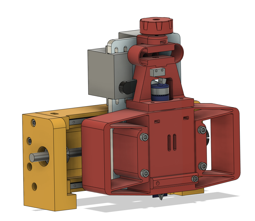
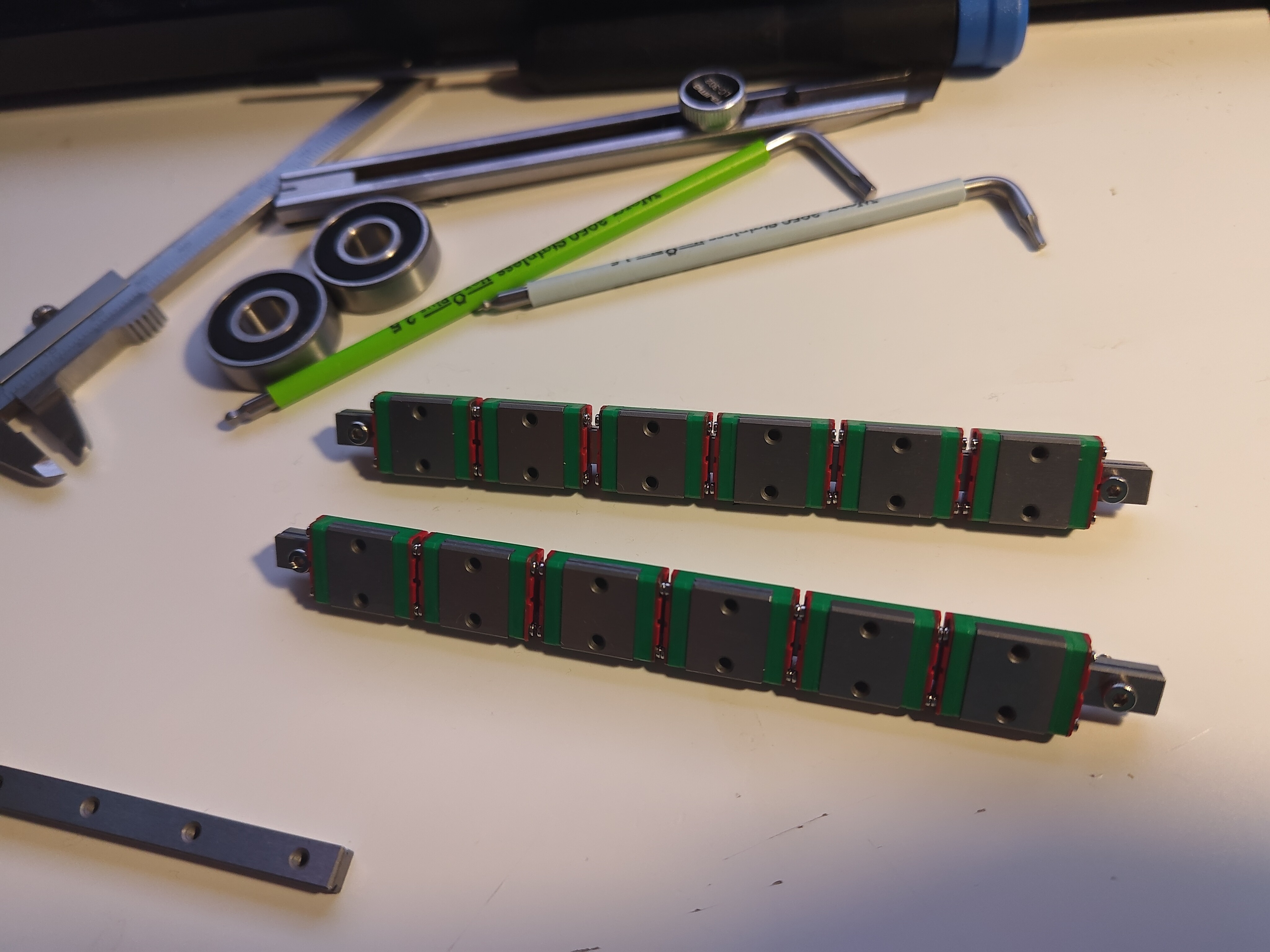
The MGN5 rails I sourced (via eBay) each had four carriages, so I transferred a bunch onto two storage rails. I'll need to fabricate storage blocks at some point, but this is fine for now:
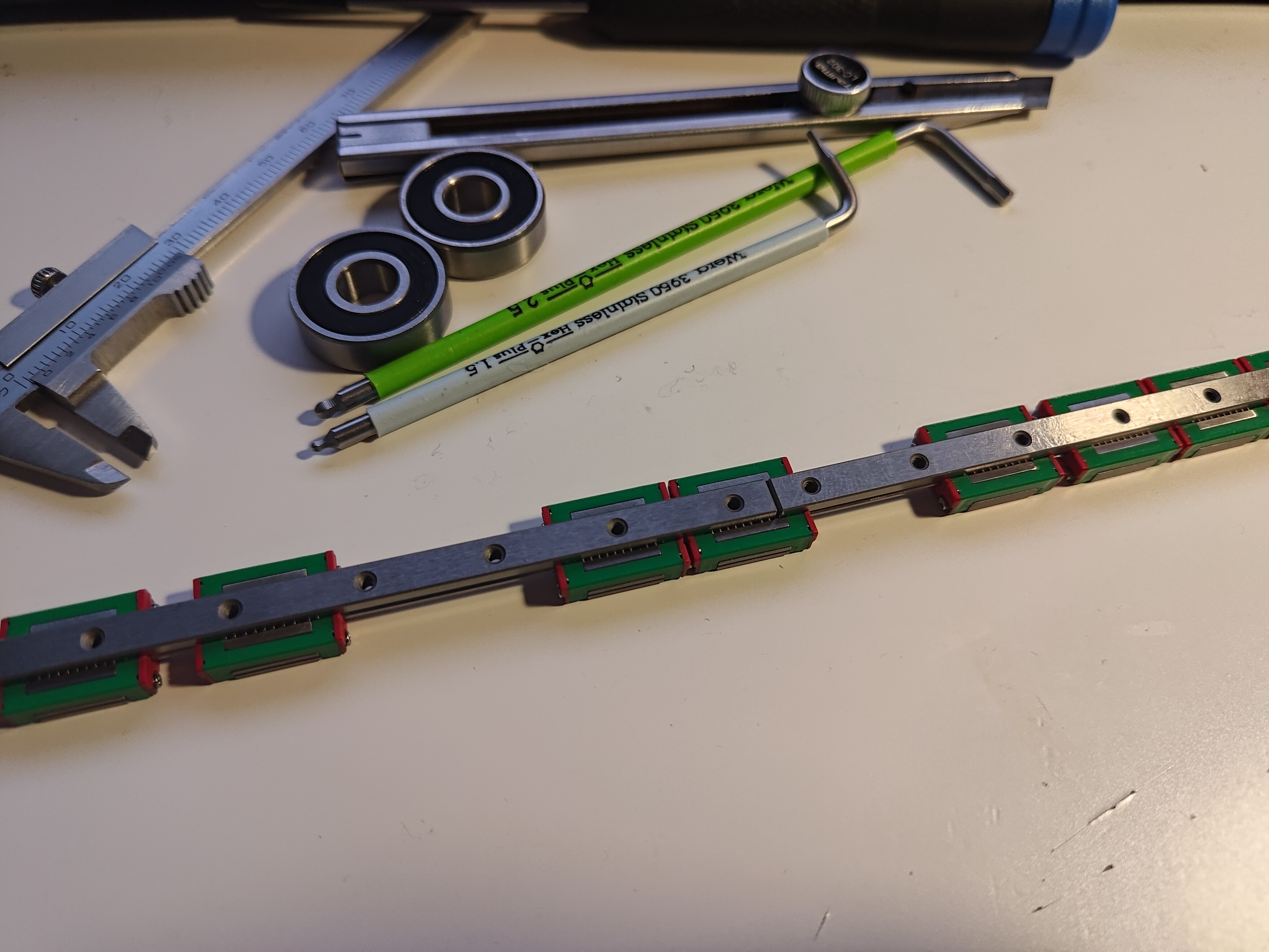
I designed and fabricated a dial indicator mount which spans a pair of MGN5 carriages, and used this to tram the top rail in against the bottom one. The mounting parallelism tolerance in the datasheet is an unlikely 2 μm, but I was still able to get within a tick (10 μm) of the indicator, so perhaps I'm only off by a factor of 2 or 3:
After tightening the rails and re-checking alignment, I mounted the plate, installed the bearings, and slid the leadscrew into place. I added a bit of lithium grease to the lead screw, and some thin synthetic PTFE-based oil to the linear guides. The lead screw is low as compared to the far bearing, suggesting I mis-measured an offset somewhere (which isn't surprising):
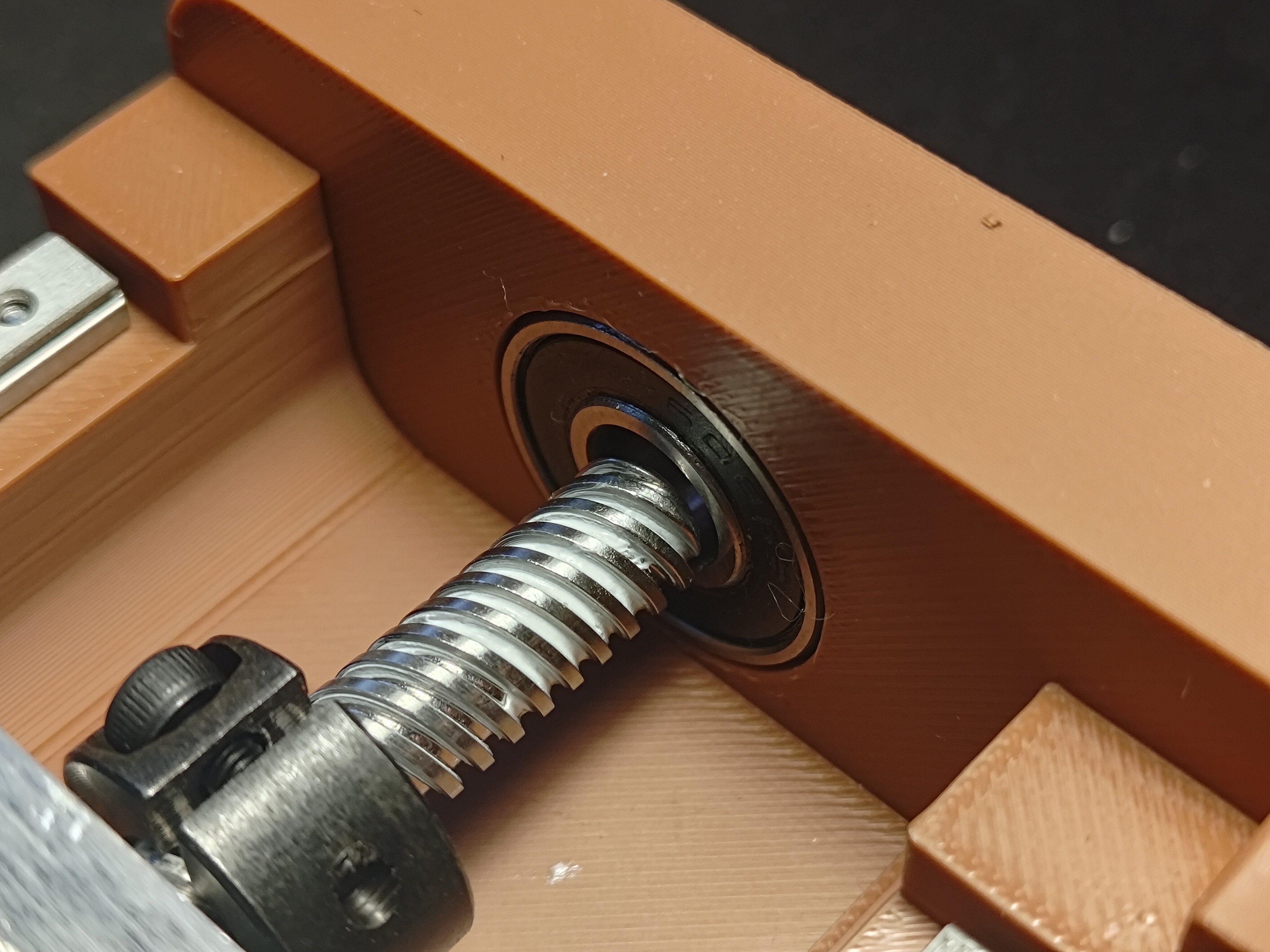
But this isn't a huge problem; there is enough compliance in the other bearing mount that the lead screw still works smoothly after applying a bit of preload. I replaced the far bearing with a blanking plate and then tightened the nearer locking collar with some manually applied axial preload on the screw itself:
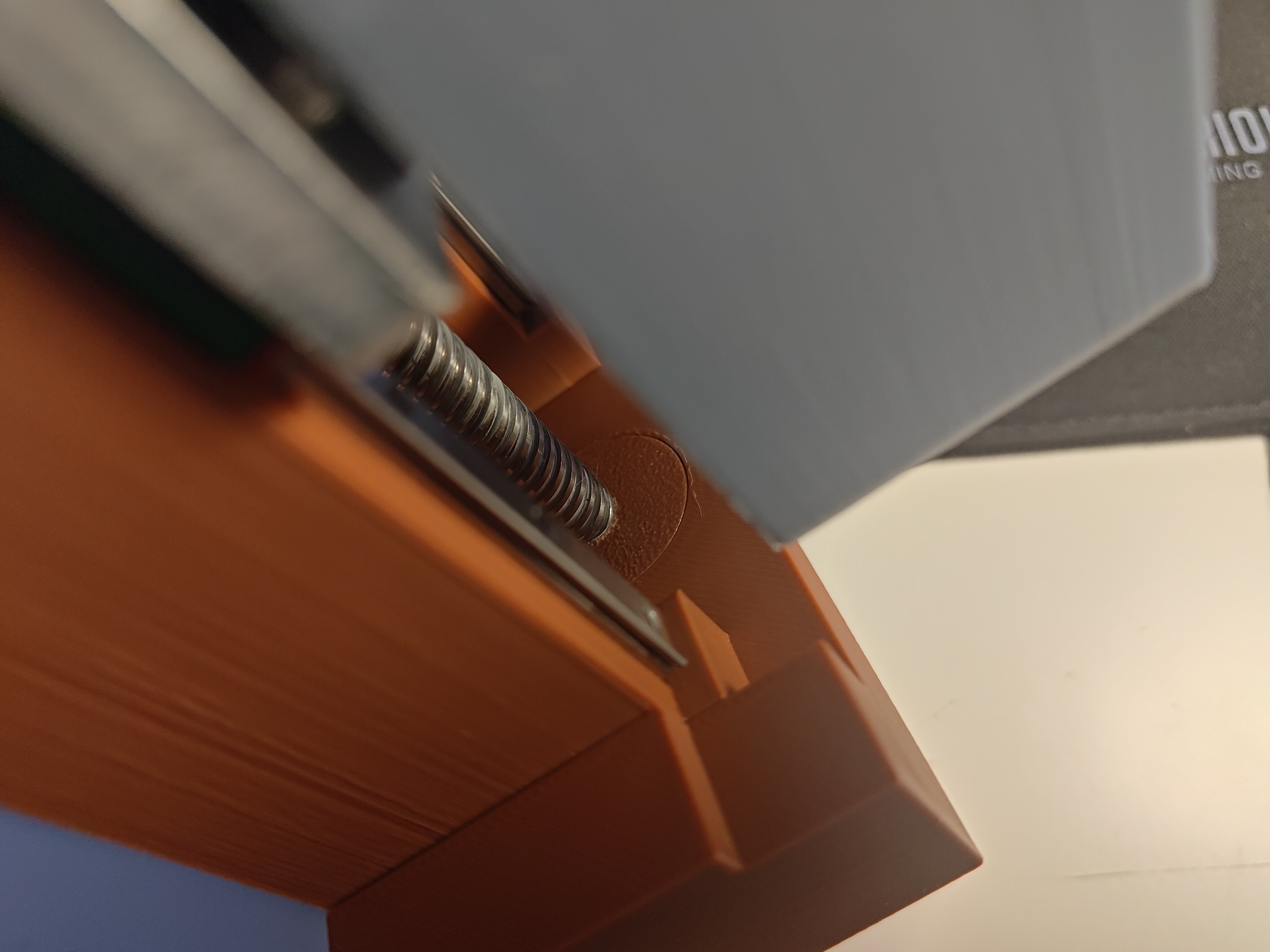
The servo got in the way so I removed it, and then installed the Z-axis flexure assembly (actually attached in the image above; I'd just forgotten to photograph the blanking plug before reassembly):
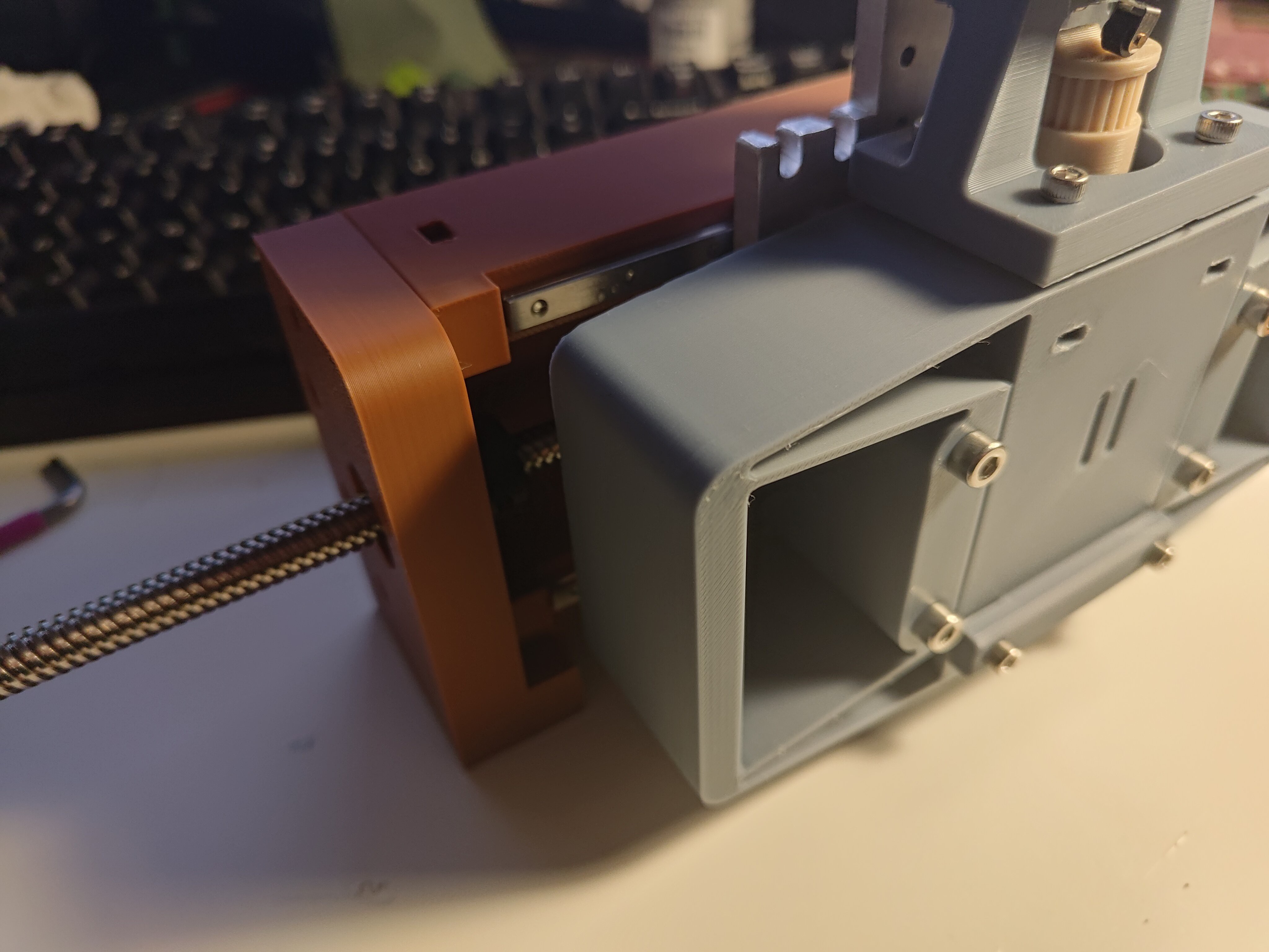
I kept the test lead screw preload flexure assembly on the far side of the lead screw, and just cranked its preload screws up so it turned into a convenient handle. I opened my recently-arrived box of PCB blanks:
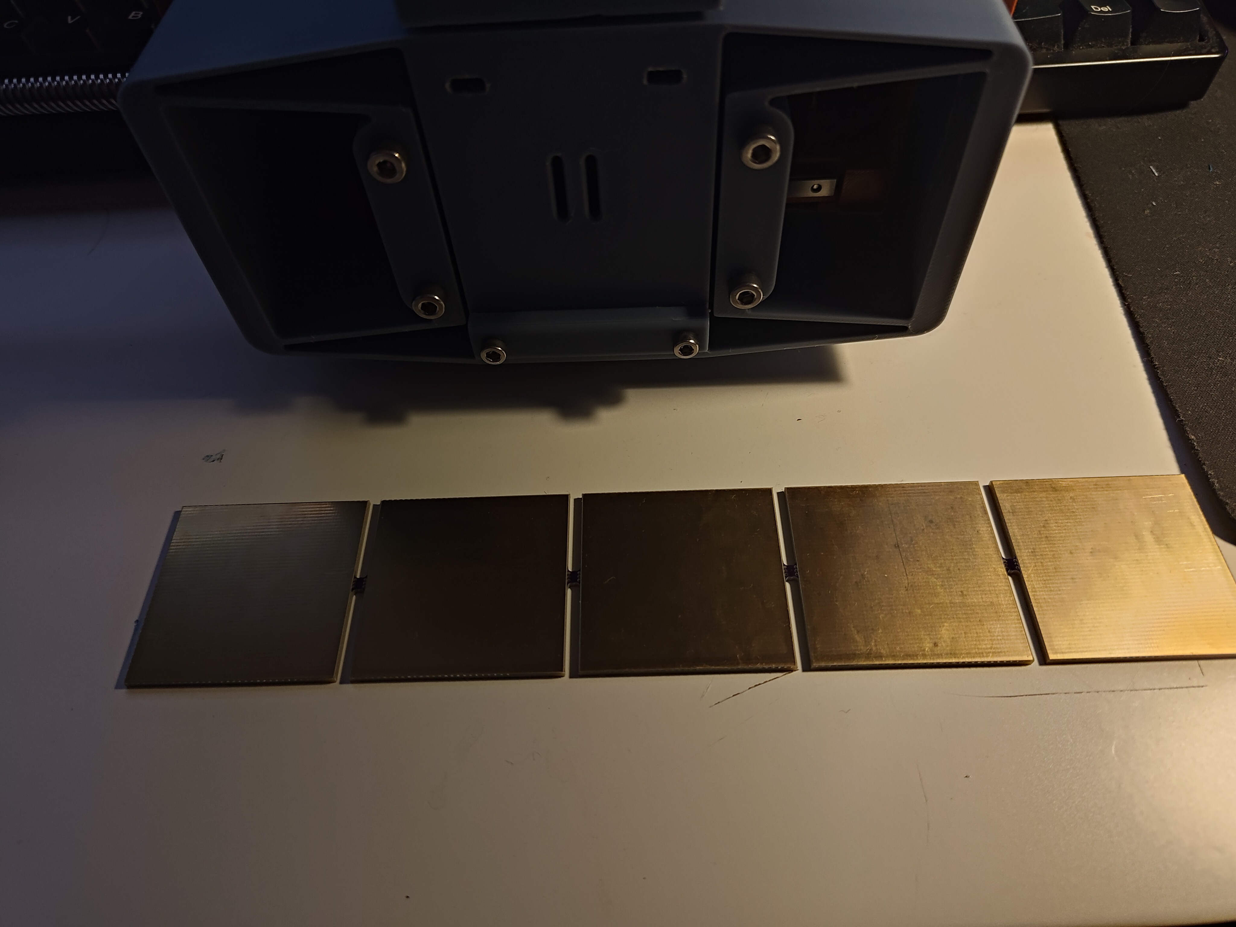
... singulated one, and secured it to the table with double-sided tape. I installed a cutter on the spindle, taped the gantry down above the PCB, and adjusted the cutting force to what seemed like a reasonable value. I advanced the lead screw to pull the cutter across the board and saw a good result on the first try:
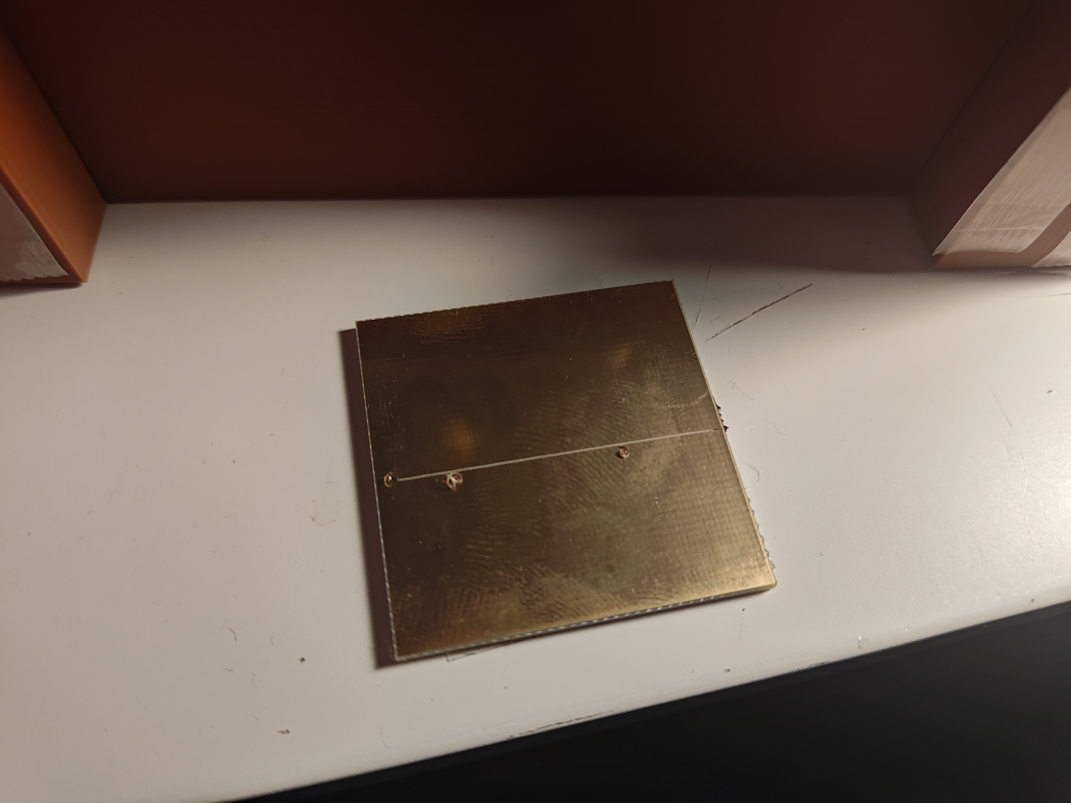
A few subsequent cuts were pretty good, and then I started futzing with preload and got some less good cuts. I think the fixturing moved a bit, or maybe the tape started bunching up and changed the height of the cutter enough to start getting worse results; in any case, later cuts weren't as great. But I think that might be related to the test setup; it's certainly not caused by the machine not being stiff enough. So the test was good! I think a reasonable next step is to design the rest of the machine: updated gantry towers (with a corrected bearing location), a static base which connects the towers, and the Y-axis assembly. One slight concern is that the machine may be quite sensitive to height, despite using pressure control for cuts; since the gantry towers will bolt in place, I may want to include some kind of precise tramming adjustment to level the table if needed.
 zakqwy
Discussions
Become a Hackaday.io Member
Create an account to leave a comment. Already have an account? Log In.