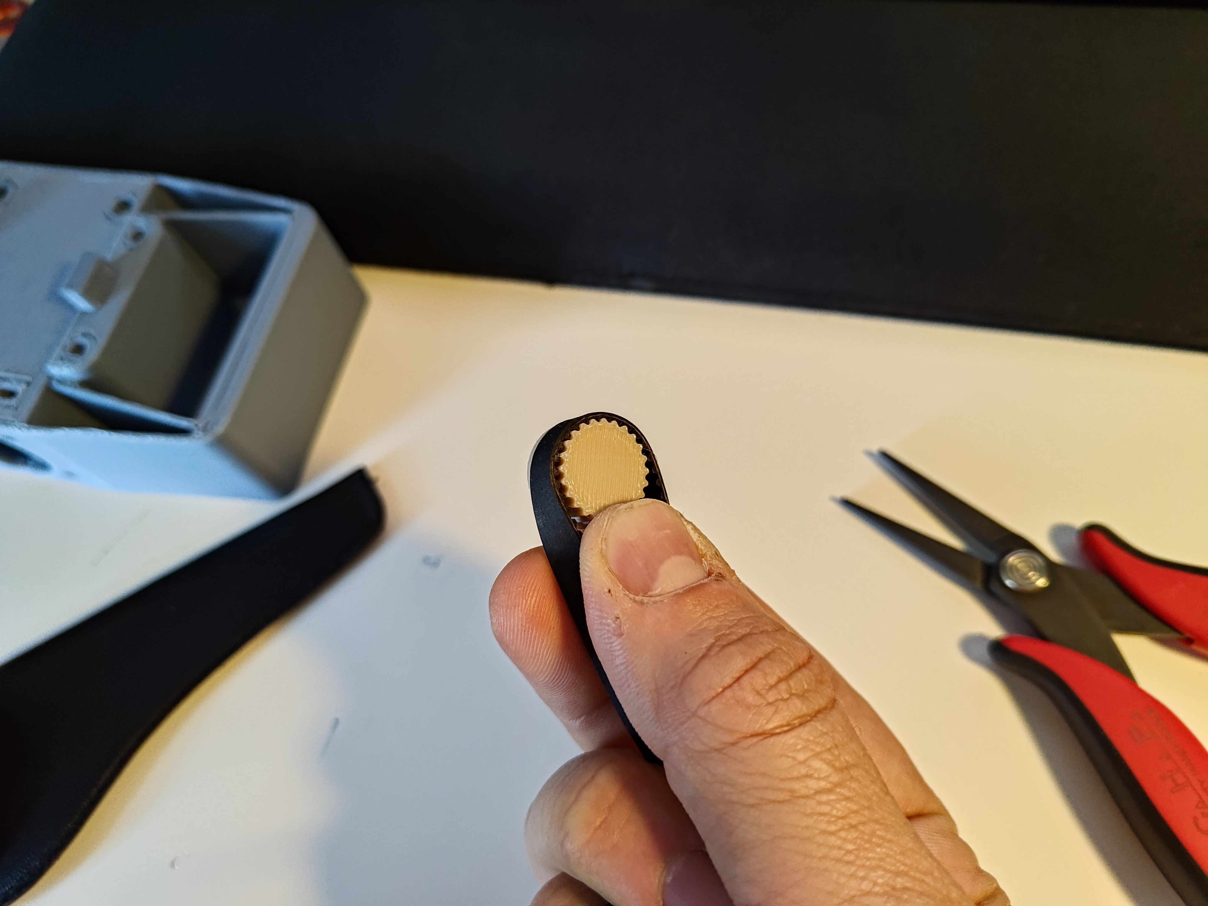
The day has arrived! I am back in town (I was here, for the 2024 edition of this), and the plate is here, so I spent a bit of time deburring the edges and holes as the aluminum was quite sharp from the fabricator. I guess I forgot to check the "deburr" box; sharp parts are annoying and dangerous, so this was time well spent, but perhaps time I'd like to hire out next time. Then I wrapped up a few design loose ends, like making some slight modifications to the GT2 tooth design for a better fit; note the slight offset on the test pinion:
... and adding a limit switch to the rotary axis. Then printing! And support material removal.
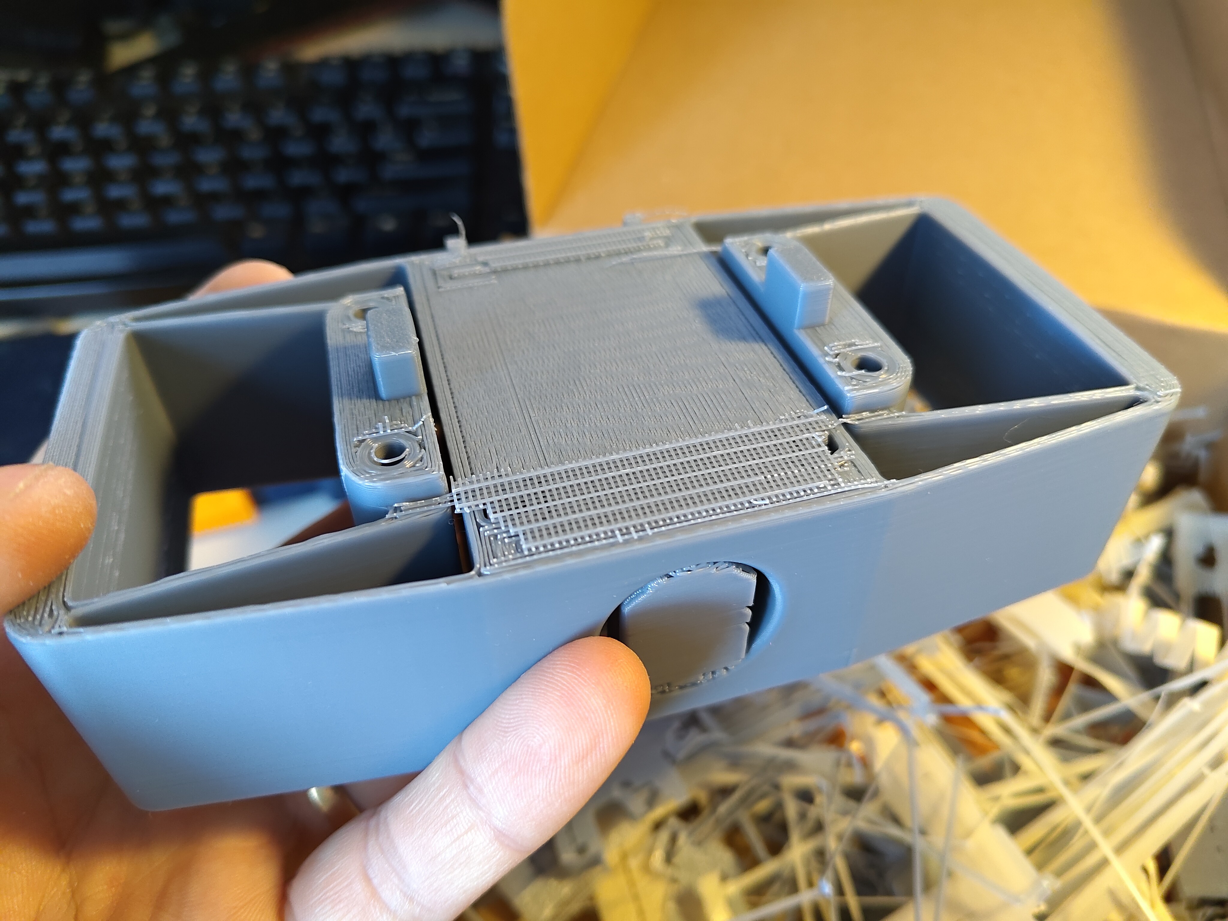
Support material isn't great, but I use it pretty liberally when I need to. It's 3D printing! If you spend all your time worrying about not using support material, it starts to feel more like 2.x-D printing. The image above is a bit extreme; the entire Z-axis flexure was printed atop a bit of support material just so I could have locating pegs sticking down (and, of course, the flexures care deeply about print orientation). But it was worth it! Locating features are so useful during assembly, and support material removal only really took a few minutes:
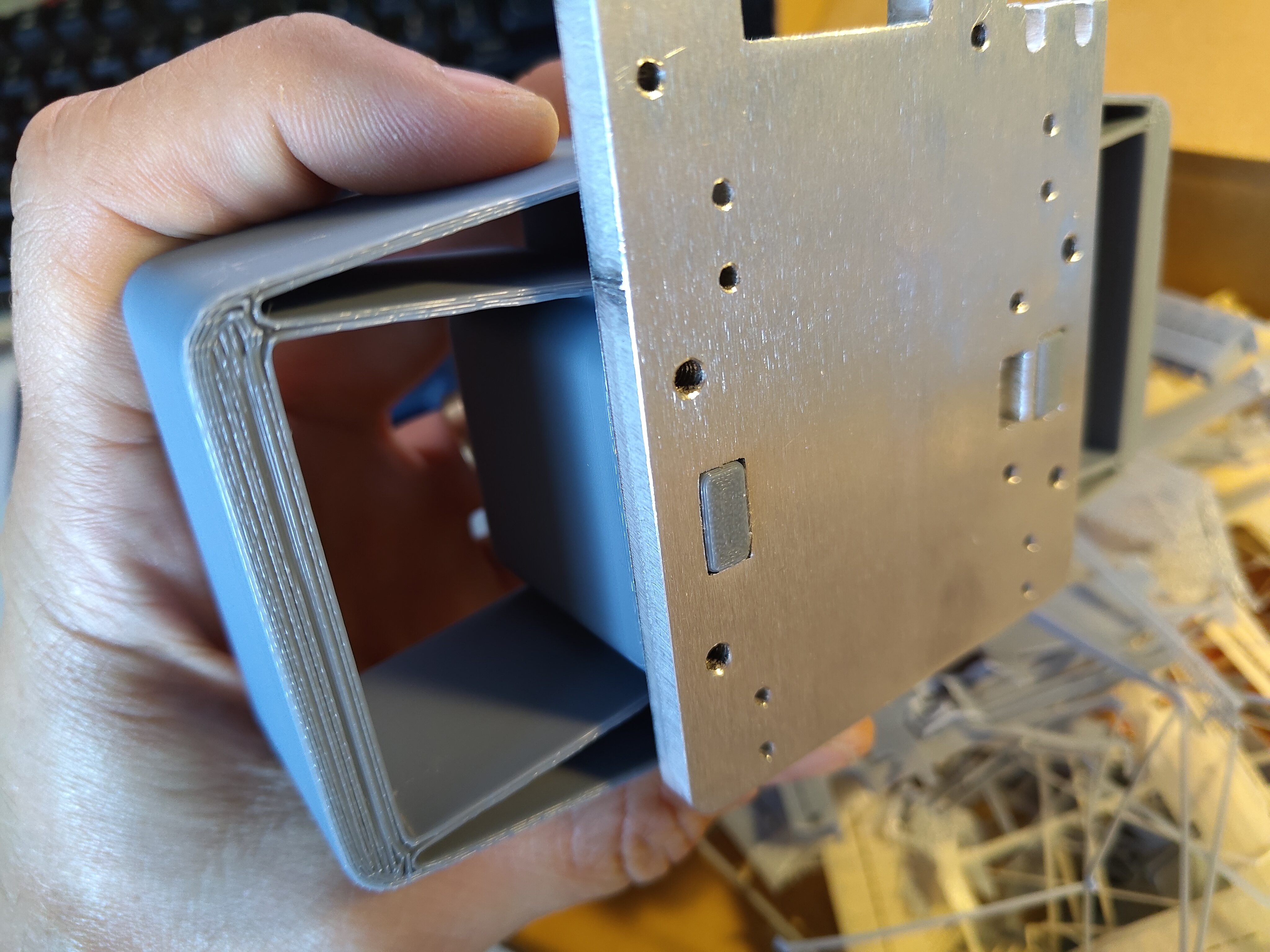
Of course, some of the other areas were more annoying; the small slots which hold the nuts which secure the top bearing cap in particular were a pain, but I think more specific tools would help there. Other parts fit together after a bit of careful hand sanding, like the bearing cap:
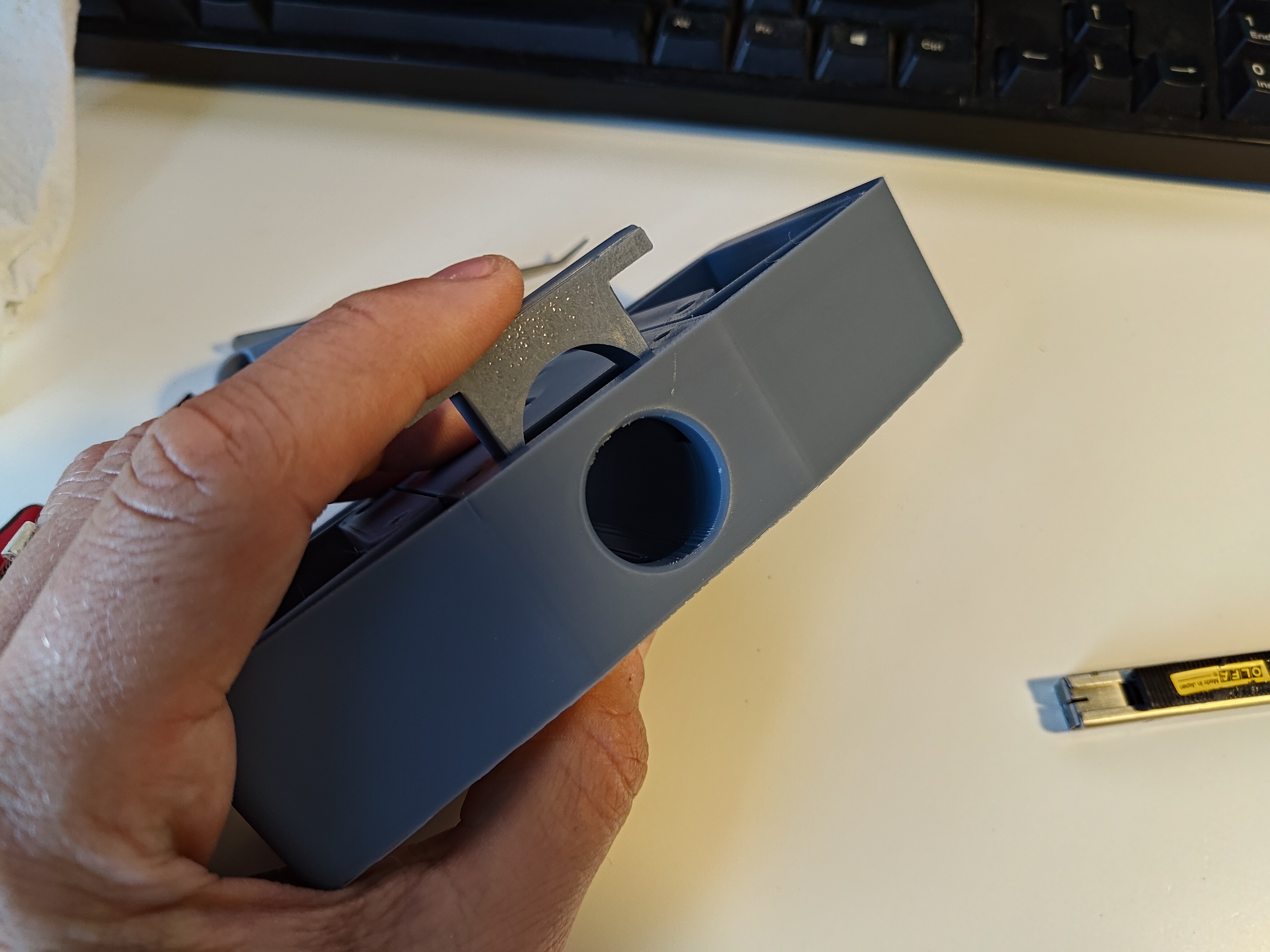
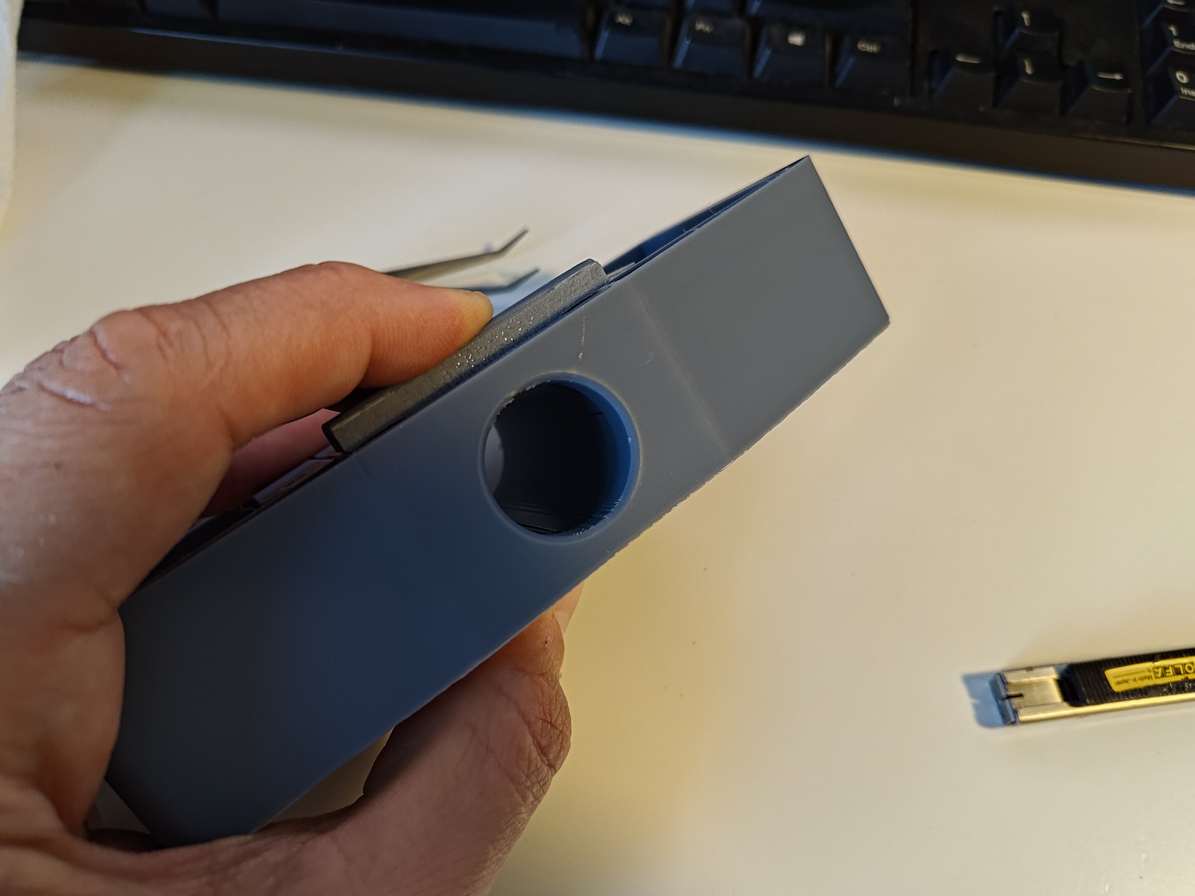
I'm rear-mounting the servo, so I filed off the tiny gusset on the front of the mounting tabs:
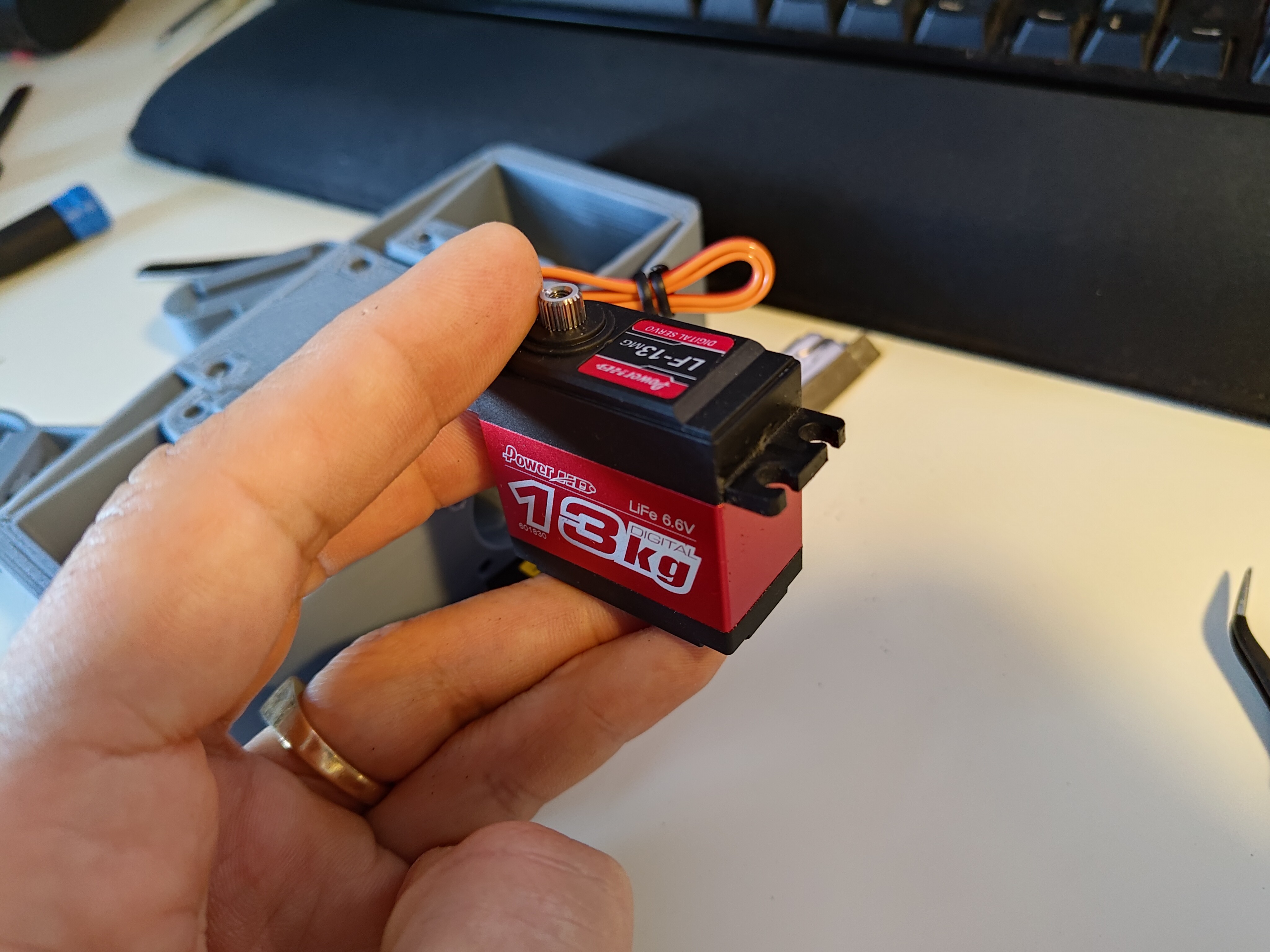
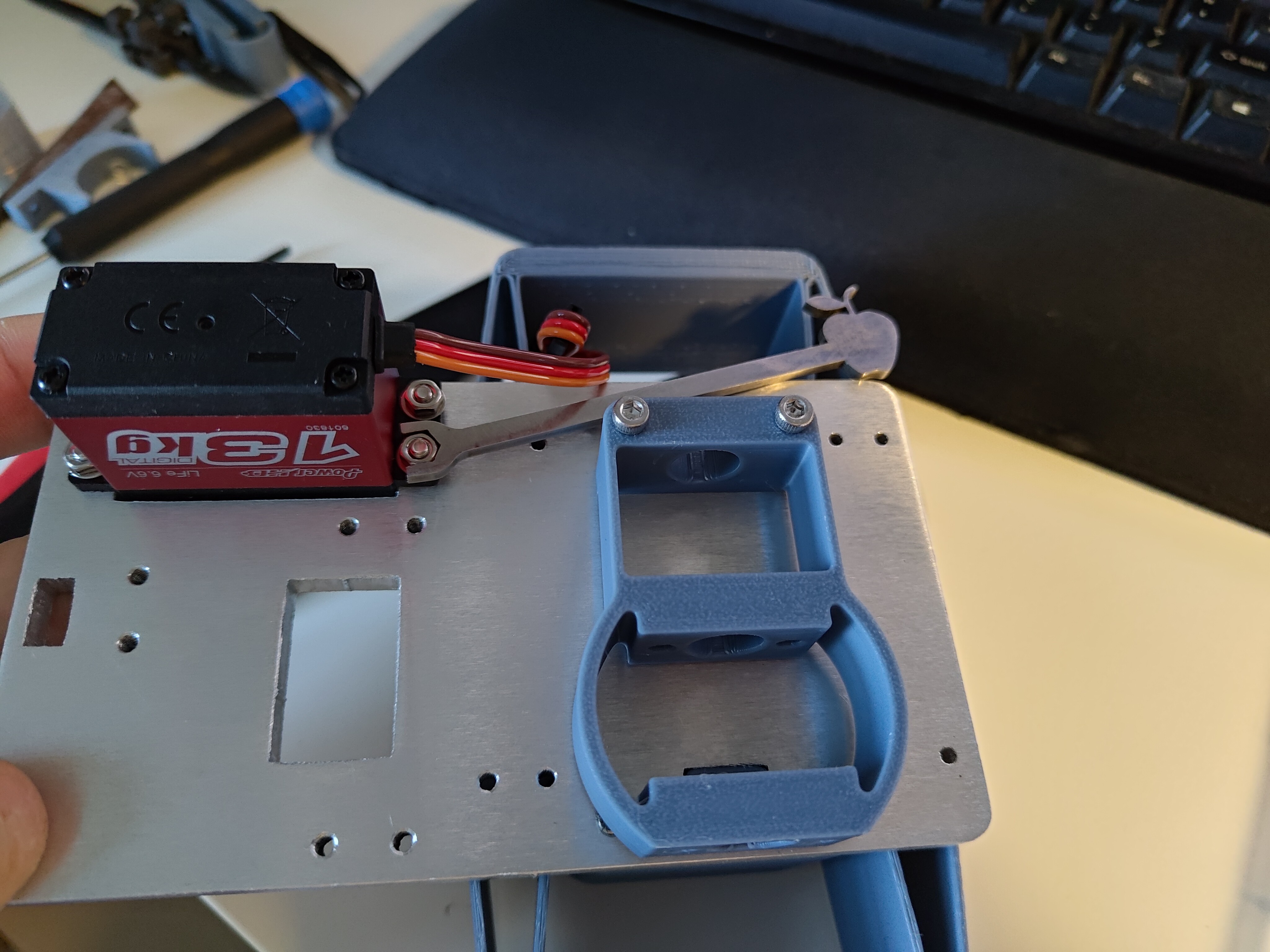
Servo installation required nuts because the holes were too close to the edge to tap, which was a great excuse to use my apple wrench:
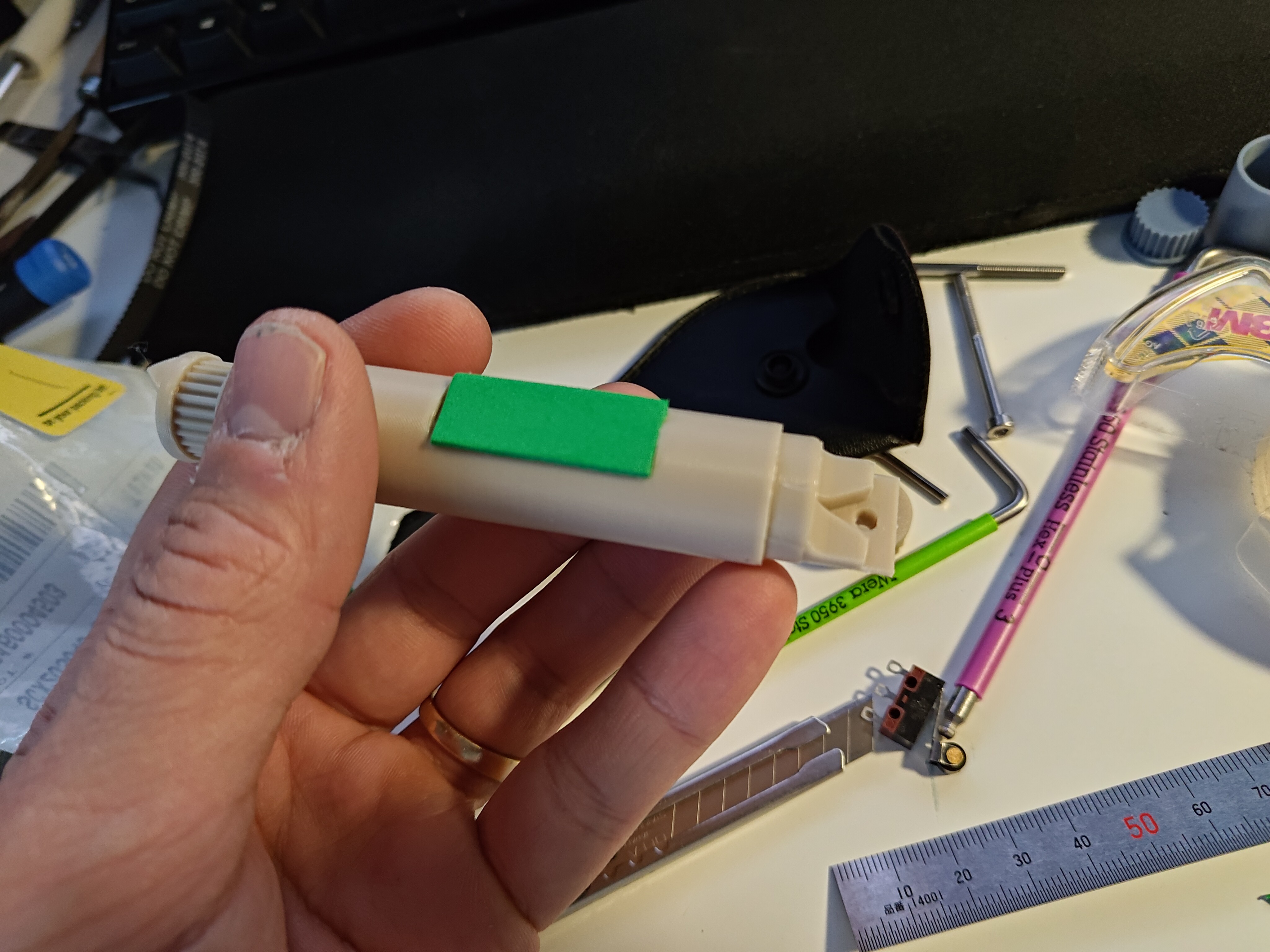
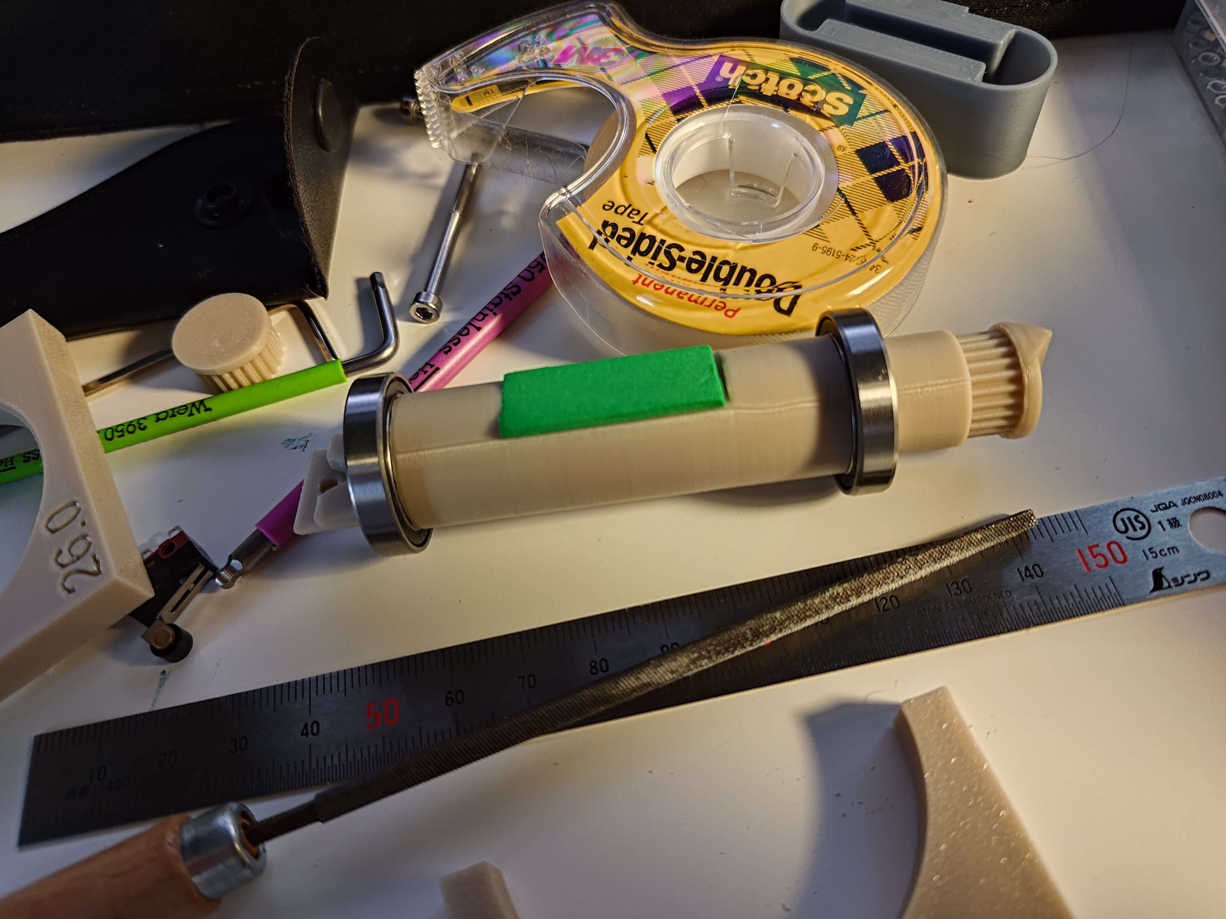
Mirroring the CAD model (at least in spirit, if not color), I made the spindle a different color than the Z-axis, and will do the same for the other part groups that move together. I also taped a bit of green EVA foam to the flat on the spindle so rotation might show up through the "nostrils":
Bearing installation went well. A few extra taps here or there, but they seated nicely and feel smooth. Yay test fits paying off!
Of course there are a few issues. Adding the limit switch was kinda afterthought-y, and I didn't have long enough bolts so the hex cutouts on the back of the bearing cap are a bit weird. And I didn't add enough clearance to install the cap mounting bolts, so I had to clearance that part a bit too with a razor:
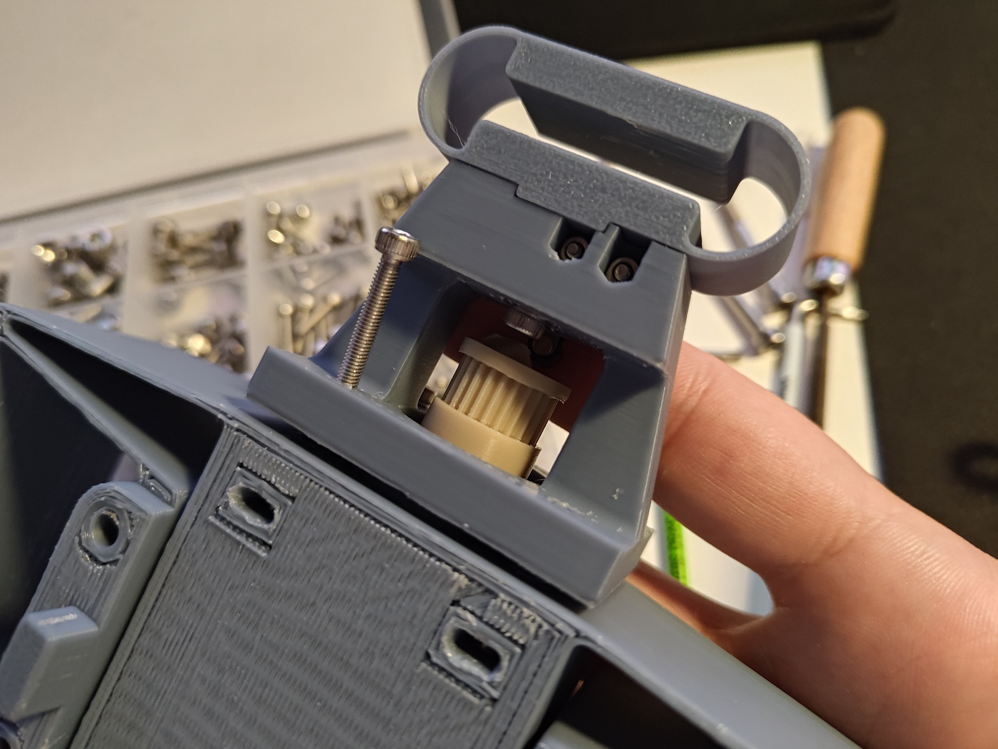
But it all came together well! The spindle rotates smoothly, the flexure moves where it should, the "downforce flexure" and cutting force knob work as they should, the servo mounts nicely, etc:
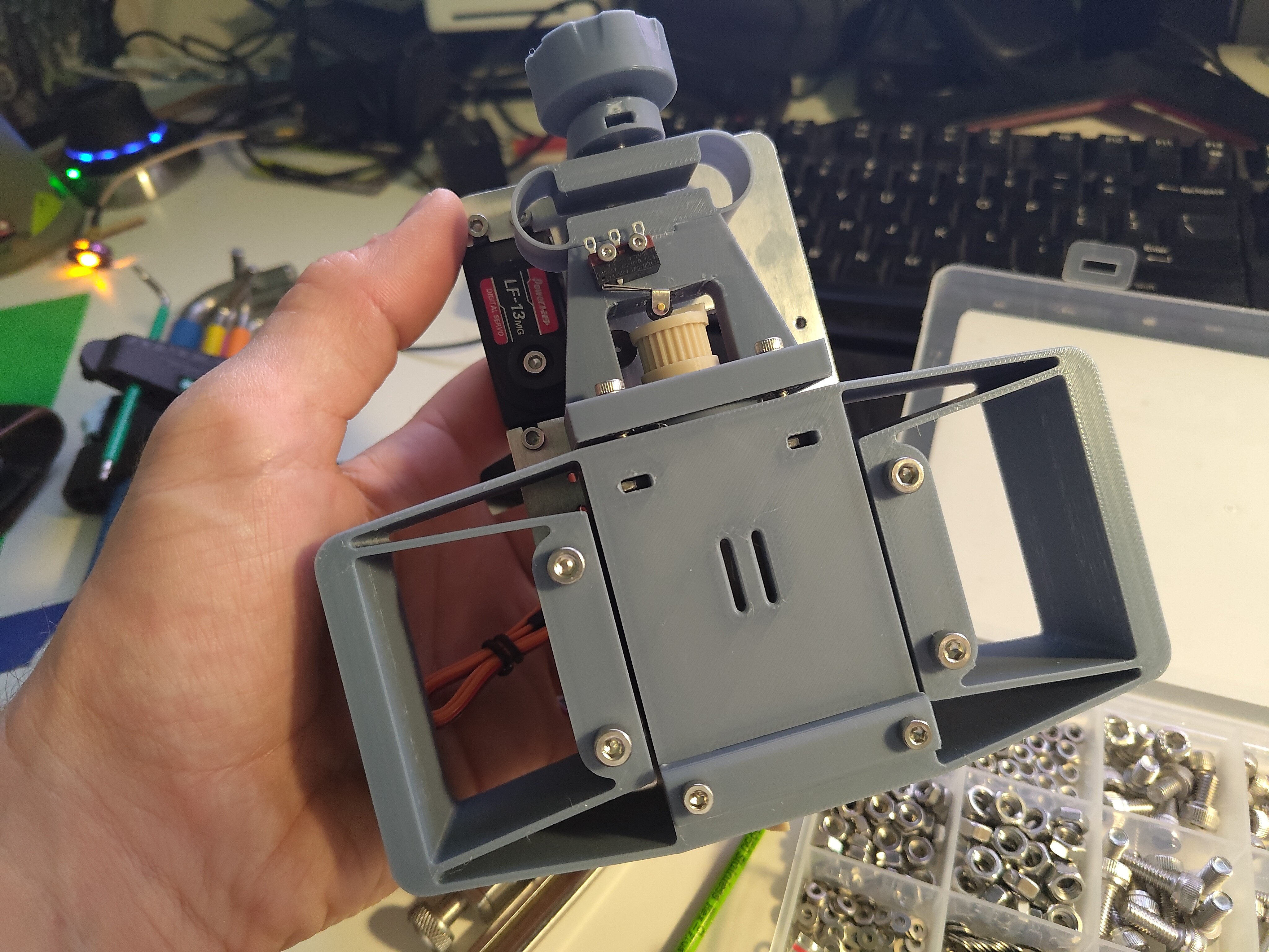
Much yet to do, of course, but this is an exciting step. I need to order a proper length belt and revise the stepper mount a bit, but then I can bolt the rest of the parts to the plate. And soon, it will be time to keep traversing the kinematic loop through the linear guides, gantry, frame, and Y-axis. I'm planning for all of those parts to be 3D printed, so hopefully the only time constraint now is me. Hah!
 zakqwy
Discussions
Become a Hackaday.io Member
Create an account to leave a comment. Already have an account? Log In.