Introduction
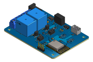
Efficient management of electrical loads is essential for optimizing performance and safety across various industrial applications. This article presents an advanced electronic board designed for controlling and actuating loads through two high-capacity relays, a microcontroller, and a digital input sensor.
The two relays on the board can handle high-power loads of up to 30A, providing a robust solution for controlling equipment and devices with significant energy demands. The microcontroller integrates and manages the operation of the relays, ensuring precise and reliable control.
Additionally, the electronic board features an input for a digital sensor that can be customized according to the user's needs. This allows the board to be adapted to a wide range of applications, from monitoring operational conditions to automating processes. All files are available for download.
See the printed circuit board presented below.
In this article, we will explore how this board can be used to control and actuate loads efficiently, leveraging the flexibility provided by the relays and the input sensor. The practical application of this system offers significant advantages for automation and load management in various industrial and commercial contexts.
Now, let’s detail the complete functionality of this innovative electronic board.
Project Electronic Circuit
First, let's start presenting the electronic schematic. The circuit below is divided into 7 parts.
Next, we will understand how each block of the circuit works. To start, let's present the power circuit block. All files are available for download.
Power supply circuit
The purpose of this circuit is to receive an input voltage between 110V and 220V from the electrical network to power the control system. See the circuit block shown in the figure below.
In the initial stage of our circuit, we incorporate a fuse (connected between U4 and U5) and a varistor (R8). This setup plays a crucial role in protecting the power supply circuit, guarding it against potential overloads or short circuits in the electrical network. This step ensures that your project remains safe and operational.
Following this, we have the Hilink U1 AC-DC converter, which converts the incoming AC voltage into a stable 5V DC. This 5V direct current is essential for powering the entire electronic circuit of the system.
Next, we use the B0505S component, labeled as U2, which is an isolated DC-DC converter. Its purpose is to take the 5V DC input and produce a separate, isolated 5V DC output. This isolated voltage is specifically dedicated to powering the ATTINY85 microcontroller circuit, ensuring that it receives a stable and interference-free power supply.
The 5V voltage from the Hilink source is also used to drive the relay circuit. By isolating the relay drive circuit from the microcontroller, we prevent any noise from affecting the ATTINY85, ensuring smooth and reliable operation.
Finally, we'll delve into the details of the ATTINY85 circuits and the signals on the energized board, demonstrating how everything integrates to make your project function effectively. All files are available for download.
Power Signaling Circuit and ATTINY85 Circuit
In every electronic project, it’s crucial to have a way to signal that the system is powered on. This particular circuit serves two important functions: it signals when the circuit is energized, helping to prevent accidents, and it aids in identifying potential issues with the power supply.
In the setup we have, a resistor is placed in series with an LED. Whenever the board is powered up and the HiLink converter delivers the 5V voltage, the LED lights up. This visual indicator confirms that the circuit is receiving power and helps you quickly spot any issues with the power supply.
The ATTINY85 circuit is quite simple. The CHIP is made up of 8 pins. Of these pins, 2 were used...
Read more » Silícios Lab


 DIY GUY Chris
 kamalkedin123
