Introduction
In many commercial establishments, hospitals and other places, there are video game equipment, beverage and food sales or laundry services. Did you know that these systems are common?
They have an electronic board that allows the use of these services when the user makes a payment using coins, bills or credit card.
The great advantage of these electronic systems is that all the machines are automatic and do not require operators to perform operations.
This allows the system to operate 24 hours a day and perform its tasks without human intervention, being a great source of income for those who want to create a service that can be used after paying a certain amount of money.
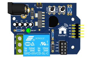
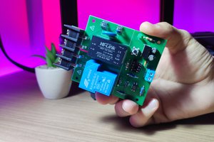
In this project, we developed an electronic board that will be used to operate with 2 types of payment: coins and credit card.
In addition, you will learn useful strategies for using this system and connecting it directly to the internet to build payment reports and other useful information for managing the business of releasing services with payments.
Electronic Project Development
Below we have the complete presentation of the project's electronic schematic. It was built and divided into 10 electronic blocks.
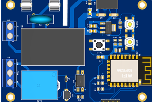
The heart of the electronic project circuit is the ESP8266 CHIP. It will be responsible for processing payments by coins and credit cards. It will then activate the relays to release products/services.
Next we will discuss how the main electronic blocks of the project work.
Power Supply Circuit of ESP8266 Home Automation Board
The power supply circuit consists of a Jack connector with a 12V input voltage. This voltage will be used to power the coin acceptor's electronic system. In addition, we will use this voltage to provide two voltage values: 5V and 3.3V, through voltage regulators.
Another element was used in this project, the isolated DC-DC converter B0505S. It was used with the aim of creating an isolated source to power the ESP8266 circuit and relay drive circuit using an optocoupler.
The objective is to create a source isolated from the main source and minimize possible interference from external noise in the ESP8266 circuit as much as possible.
As you can see, there are two 5V power supplies isolated from each other, each one has its own GND.
The +5V isolated voltage source is used at the input of the +3V3 voltage regulator circuit.
It is through this voltage regulator that the ESP8266 circuit is powered.
Electronic Circuit of the ESP8266
Below we have the basic operating circuit of the ESP8266. Upon connecting the ESP8266 to power and its basic components, the ESP8266 will execute its control firmware.
Associated with this circuit, we have the programming mode configuration block, which is made up of two buttons. These two buttons are responsible for putting the ESP8266 into programming mode.
This way, you will be able to transfer code to your ESP8266. Code transfer is carried out through the pins of the circuit block below.
Your code will be stored in the ESP8266's memory and will be ready to control the relay to activate the load you desire.
After all, how does the relay activation circuit work?
Coin Acceptor Module
The electronic coin acceptor is a key component in many payment systems that use coins to unlock the use of services. This device is responsible for receiving coins and emitting signals that indicate the total amount inserted, facilitating the automation of payments in a wide variety of applications, from automatic vending machines to access control systems.
The Role of the Electronic Coin Acceptor
Electronic...
Read more » Silícios Lab


