If you have followed my previous project to reuse a fridge compressor as a vacuum pump you know that start/stop of this compressor can wear the contacts of the relays I used.
A friend of mine bought a DC motor diaphragm pump on Aliexpress.
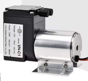
This pump has the following specifications :
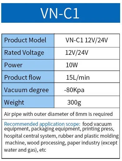
you can find it easily on Aliexpress : DC Diaphragm 12v/24v Small Mini Air Vacuum Pump VN-C1 For Medical Cosmetology
The pump we have is the 12V model.
So I had to modify my electronics board to adapt it to this DC motor.
On this video you can see the system running on a VN-C4 pump. VN-C4 is a piston pump more powerful than the VN-C1 (but I stil prefer the VN-C1 !)
However the system runs with the same software !
Have a look to this log to see how the system is integrated with an intake valve.
Electronic board to automate the vacuum pump
Schematics
Schematics of this board are a little more complex but remain very simple!.
- An ESP32 microcontroller will handle all the logic and communication with smartphone over Bluetooth Low Energy and WIFI over UDP
- two 5V relay boards can handle the fridge motor coils (compatibilty with fridge compressor)
- an OLED display could be used for debugging
- a pressure sensor will convert vacuum level into a voltage read by the ADC of the MCU
- a DC motor can be controlled via N channels Mosfets
- a brushless DC motor can be controlled with an ESC controller (optionnal 5V control stage)
- The board is powered (optionnaly) with a cheap 12V to 5V DC/DC converter
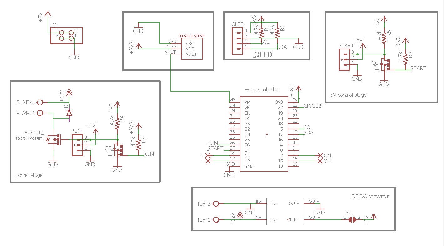
So this board should be more versatile than the previous one as it can hadle a least 3 types of pumps:
- 230V AC fridge compressor
- 12V/24V DC diaphragm pump
- Brushless DC diaphragm pump
But we will focus on controlling the simple 12V DC motor pump.
PCB
Routing this simple schematics was fairly easy.
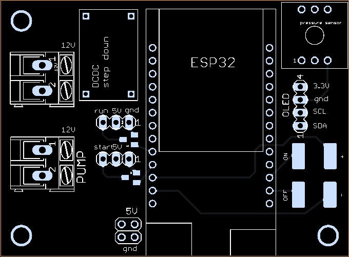

PCBWay kindly proposed to sponsor this project and has produced professionnal looking boards.
Quality is, as usual, excellent and the black silkscreen beautiful !
If you want to get one, simply follow this link : Vacuum Pump V2 @PCBWay
Soldering this board is fairly easy, even the small N channel Mosfets can be manually soldered.
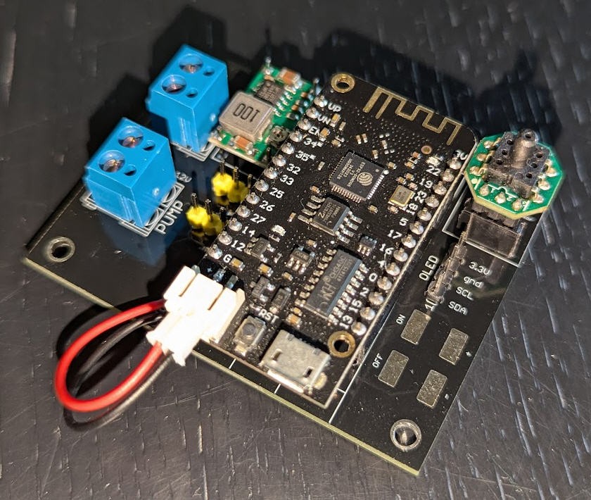
The Bill of material is available here : BoM for DC motor vacuum pump. Total price is around 45€
Warning : before soldering the ESP32 tune the DC/DC converter so that its output gives 5V
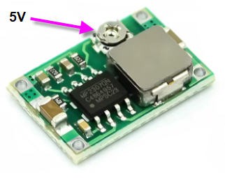
These sensors are extremely cheap and can be found on AliExpress
Pressure sensor
I choose this kind of sensor easily available on aliexpress:
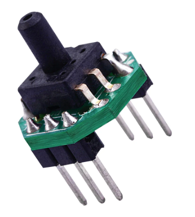
Many references does exist, you have to select the right one: DC0.2-2.7V Barometric Gas Pressure Sensor Transmitter PCB Module Vacuum Negative Pressure -100 to 0kPa
- power is DC 3.3V
- pressure range should be for vacuum between -100kPA to 0 kPA
With a 3.3V device the output signal will be between 0.2V to 2.7V which is perfect for the ESP32 ADC levels
Datasheet was hard to find, but here it is : XGZP6847A Pressure Sensor Module
And here is its response when applying vacuum:
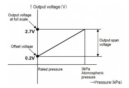 It is the same sensor as already used for the fridge vacuum pump. The DC motor pump is a little weaker than the fridge and can "only" produce 80kPa vacuum. And this is really more than enough!
software
software is more or less the same as for the fridge compressor.
I have however upgraded the ESP32 arduino code which is available here : DC motor vacuum pump firmware
For the sake of readability I reproduce here the existing documentation for the code (including the upgrades)
Firmware of the ESP32 could have been extremely simple as we basically just want the following features:
- start the pump
- [new] PWM power of DC motor pumps
- read pressure
- stop the pump if highVacuum is reached
- resume pump if low vacuum is reached
But I wanted something a little more user friendly:
- smartphone application with BLE communication with the ESP32 (optionnal)
- [new] smartphone application with UDP communication with the ESP32 (optionnal)
- monitoring of pressure and user interface on the smartphone (optionnal)
- touch pads on the PCB board to run the device without the smartphone (optionnal)
- LCD screen (optionnal)
Finally software is thus divided into two parts:
Both are available into my github pages here : Vacuum Pump @github
The system can work without the android App.
Firmware is handling a finite state machine which is easy to understand:
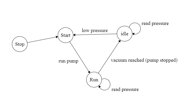
Man Machine interface (MMI) can jump to "start" or "stop" status into this graph. When booting the ESP32, the status is set to "Start" allowing the pump to immediately enter into a "vacuum" cycle without any user intervention.
MMI can also set "low" and high" pressure thresholds used to control the vacuum. User can interract with "ON", "OFF", "+" and "-" touchpads on the PCB.
"+" and "-" pads will respectively increase and decrease thresholds:
- highPressure threshold when "START" touchpad is tapped while "+" or "-" is kept touched
- low pressure threshold when "STOP" touchpad is tapped while "+" or "-" is kept touched
LCD displays real time status of the pump:
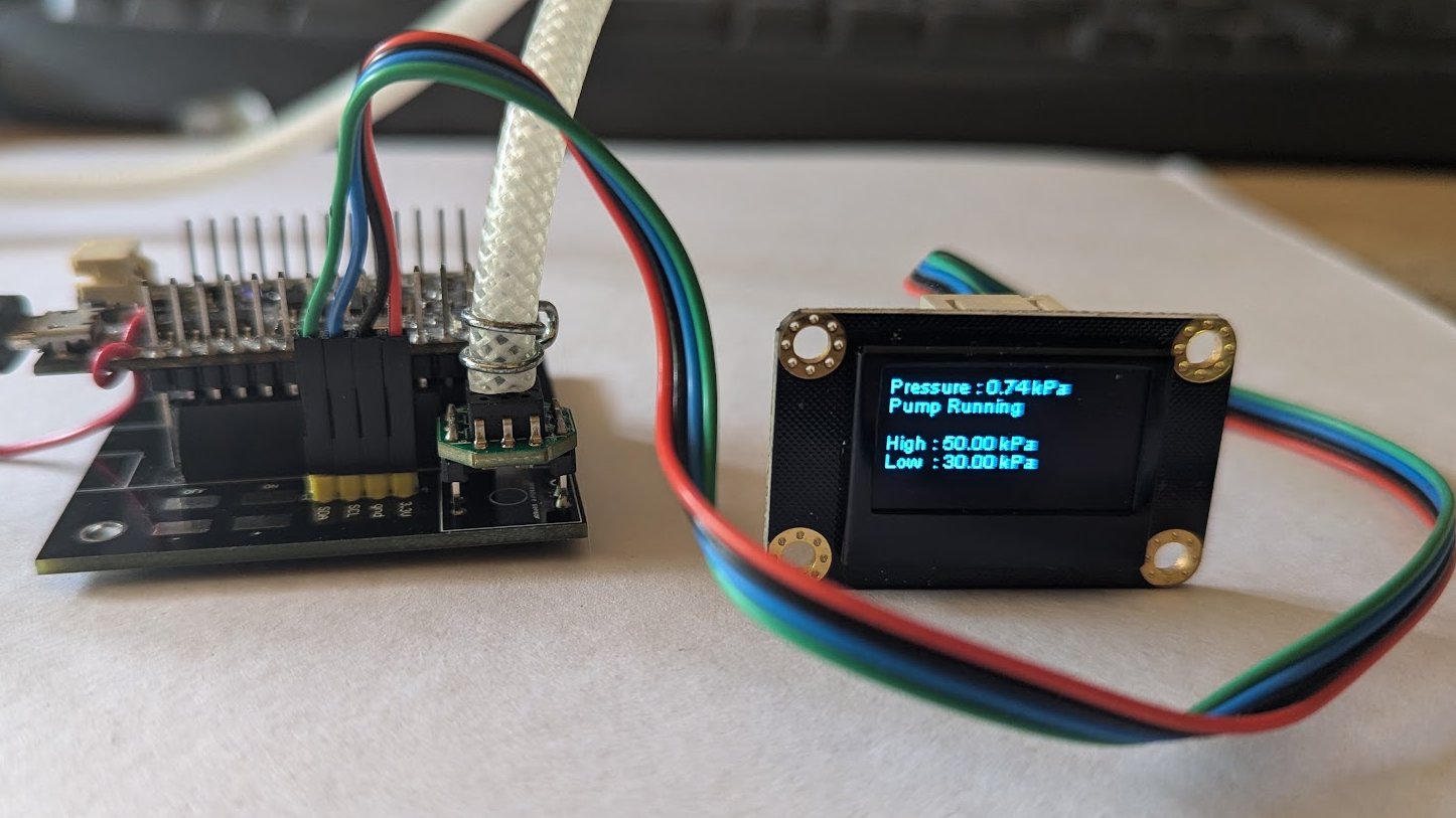 If you open the arduino firmware source code you will find two "#define" lines
RESTART_DELAY allows to tune the delay between two start/stop/start operation of the motor. This value is important for fridge compressor and should be above 4000ms. For a DC motor pump a 1s delay is enough
DC_PWM_MOTOR, when defined, allow to drive the DC motor pump with a PWM. This signal is output from the "RUN PIN" of the microcontroller via the big N channel mosfet. With a PWM we can easily modify the speed of the motor. This is used to have a less noisy behavior of the pump:
when vacuum bag is in open air, the pump will start at full speed
when entering close to the regulation pressure band (between low and high pressure) then the pump will have a rotation speed directly proportionnal to the pressure. This allows to reduce significantly the noise of the pump. See (listen to) the following video to better understand;
code to tune the pump speed is very simple:
#ifdef DC_PWM_MOTOR
  ledcAttachPin(RUN_PIN, 0); // assign PWM pins to channels
  // Initialize channels : ledcSetup(uint8_t channel, uint32_t freq, uint8_t resolution_bits);
  ledcSetup(0, 24000, 11); // 24 kHz PWM, 11-bit resolution (range 0-2047)
  //start pump driver
  pwmSpeed = 2047;           //pump stopped at startup (range 0 to 2047)
  ledcWrite(0, pwmSpeed);
#else
  pinMode(RUN_PIN, OUTPUT);
  pinMode(START_PIN, OUTPUT);
  digitalWrite(START_PIN, HIGH); //start coil not powered
  digitalWrite(RUN_PIN, HIGH);   //run coil not powered
#endif
and when the pump is in the "RUN" status
    case statusRun:
      lastStart = millis();

#ifdef DC_PWM_MOTOR
      pwmSpeed = mapfloat(pressure, 0, 100, 1500, 0);   //control pump speed with pressure value
      if (pressure < lowPressure * .5)  pwmSpeed = 0;
      ledcWrite(0, pwmSpeed);                           //PWM to the pump
#endif
configuring the wifi
The board can now communicate with the android application both via Bluetooth Low Energy and UDP over wifi.
To configure the wifi simply follow this procedure:
I have simply used the ESP32 WifiManager library capabilities to enter wifi credentials on the ESP32 board.
So if you boot the board (or reset it with the reset button) while touching the "OFF" touchpad on the lower right corner of the board, then the ESP32 exposes a Wifi hotspot (named "JP VacuumPump" on which you can connect any smartphone (or PC)
Connecting to it will automatically open a configuration window
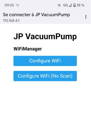
You then have to choose an exisitng wifi network for which you have the credentials, enter them into the form
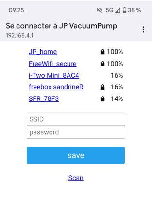
Your ESP32 board is now configured to run with wifi and you would be able to monitor your vacuum bagging process in your garage while looking at TV in your living room!
Put it into a box
I have designed a small 3d printed box where everything can fit.
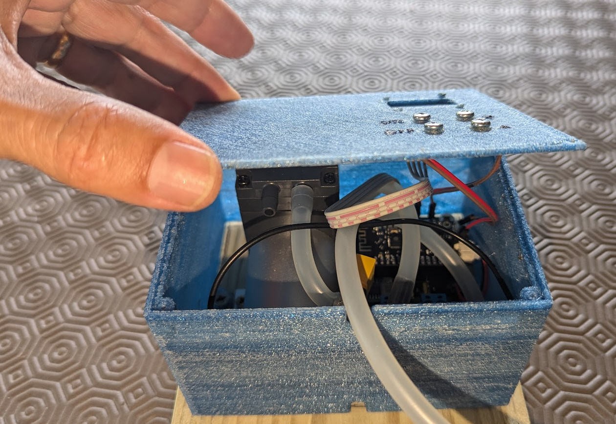
screws on top of the box allow to connect touchpads. (simply solder wires to the corresponding pads).
Leaks...
But after connecting all this with good fexible pipes, I still had "bad" leaks and the regulation was triggered too often...
I finally discovered that the leaks were inside the pump. It leaks at the airflow side (oulet)... If you put a finger on the airflow exit when the pump is idle... it is sucked, so the inside valve leaks.
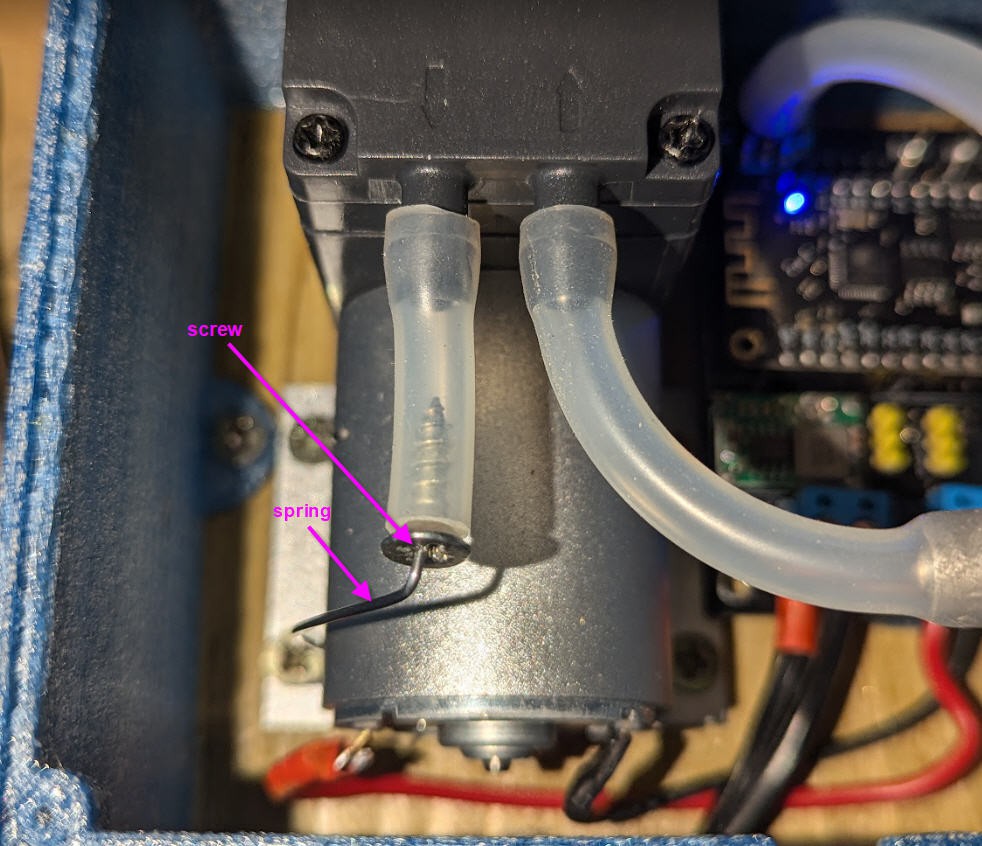
So I decided to add another valve. It was very simply made with a "conical" screw inserted into a piece of pipe. The screw being held in place with a spring made with "piano wire 1mm diam". The sprinf is pushing the screw into the pipe. Be sure to cut the pipe very cleanly so that the inner diameter is a perfect circle where the conical screw can fit.
See picture to better understand:
With this valve the delay between two Start/Stop is around 4 to 5 minutes.
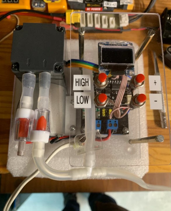
And if you want something even better, just add a small plastic valve into the intake pipe as close as possible to the pump. (Here one valve on the intake and one (useless) at the output.).
With this configuration and a sealed bag, the pump doesn't leak and regulation occurs every hour or so.
 JP Gleyzes