 Shoaib Mustafa
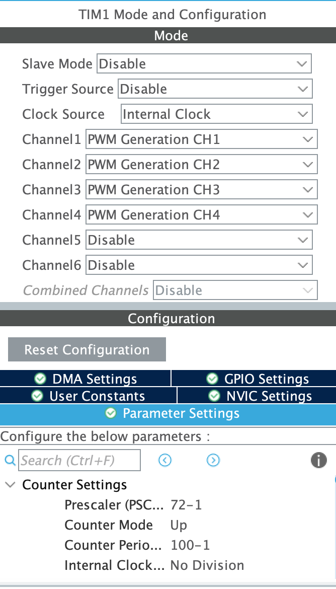
The pins essentially serve as output points, with the main operation driven by the clock. I first identified which timer each pin was associated with. In this case, the pins are linked to Timer 1, specifically channels 1, 2, and 3. I enabled them one by one, setting the clock source to internal since my board doesn't have an external source. I then configured the settings, paying close attention to the prescaler and period values, which determine the frequency. The frequency can be calculated using the following equation:
For my setup, the APB1 clock speed was 72 MHz. So, the frequency was:
If a 1 kHz signal is desired, only the period needs to be adjusted. The equation then becomes:
For 1 kHz:
Period = 999
I confirmed with an oscilloscope that the frequency was indeed correct.
I then switched to the STM32 to take advantage of its 16-bit PWM capability, which allows for values between 0 and 65535. However, I'm not yet certain if it can generate a 1 kHz signal with 16-bit resolution—I'll need to investigate further.
The resolution can be calculated with the formula:
For a period of 999:
This is approximately 10 bits, offering 1024 discrete steps, which is better than the 8-bit resolution with 256 steps. However, I'm curious if it's possible to achieve 16-bit resolution while maintaining the same frequency. My question is: why should the signal frequency matter when we're only concerned with the duty cycle?
The pins were selected as follows:
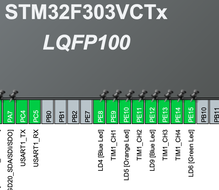
The setting of the PWM channel was done as:
Discussions
Become a Hackaday.io Member
Create an account to leave a comment. Already have an account? Log In.