0%
0%
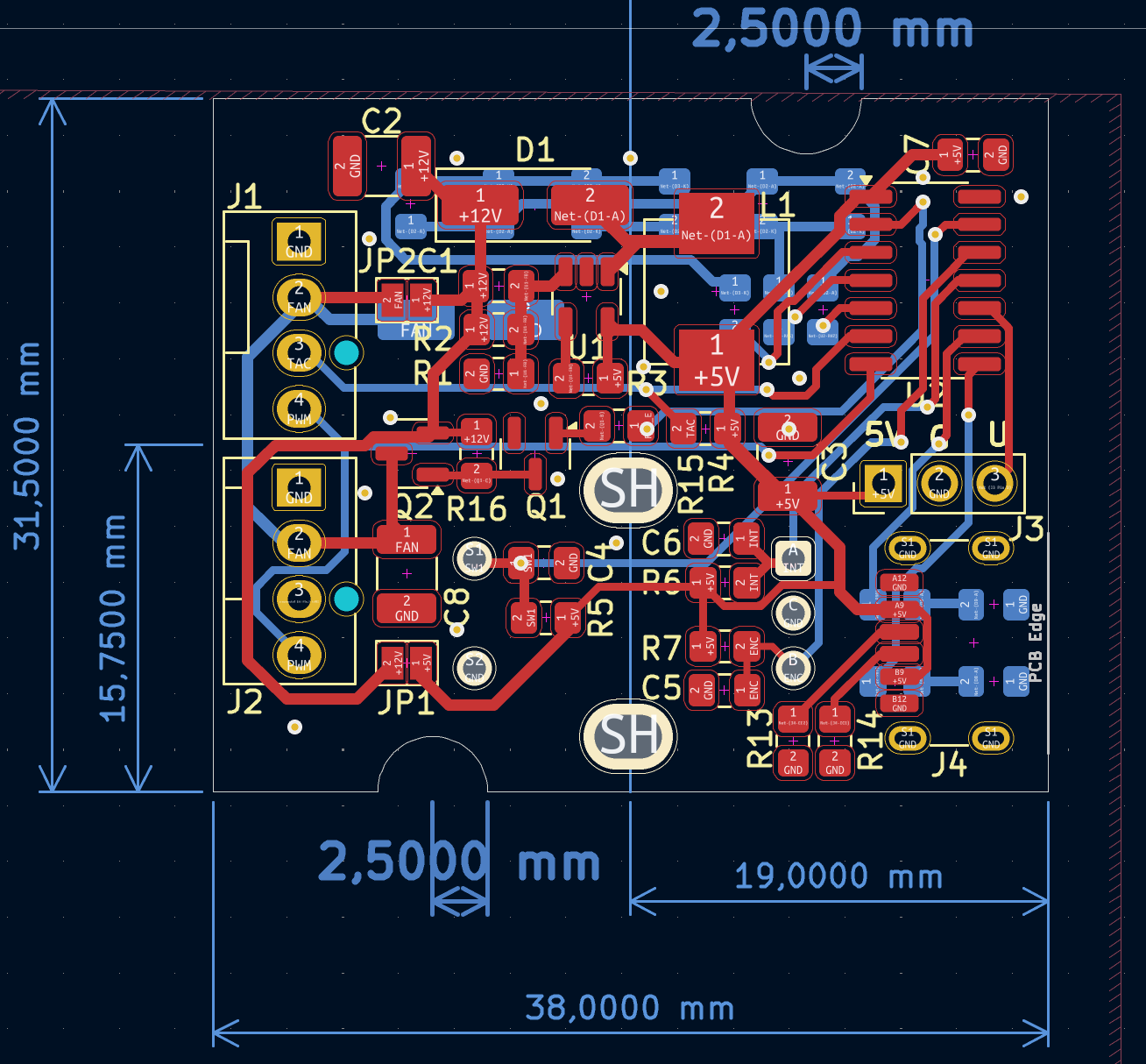
USB Powered 12V Fan Controller
A small fan controller for 12V Casefans powered from 5V. With built-in Splitter
 FoxHood
Become a Hackaday.io member
Already have an account? Log in.
Just one more thing
To make the experience fit your profile, pick a username and tell us what interests you.
Pick an awesome username
hackaday.io/
Your profile's URL: hackaday.io/username. Max 25 alphanumeric characters.
Pick a few interests
Projects that share your interests
People that share your interests
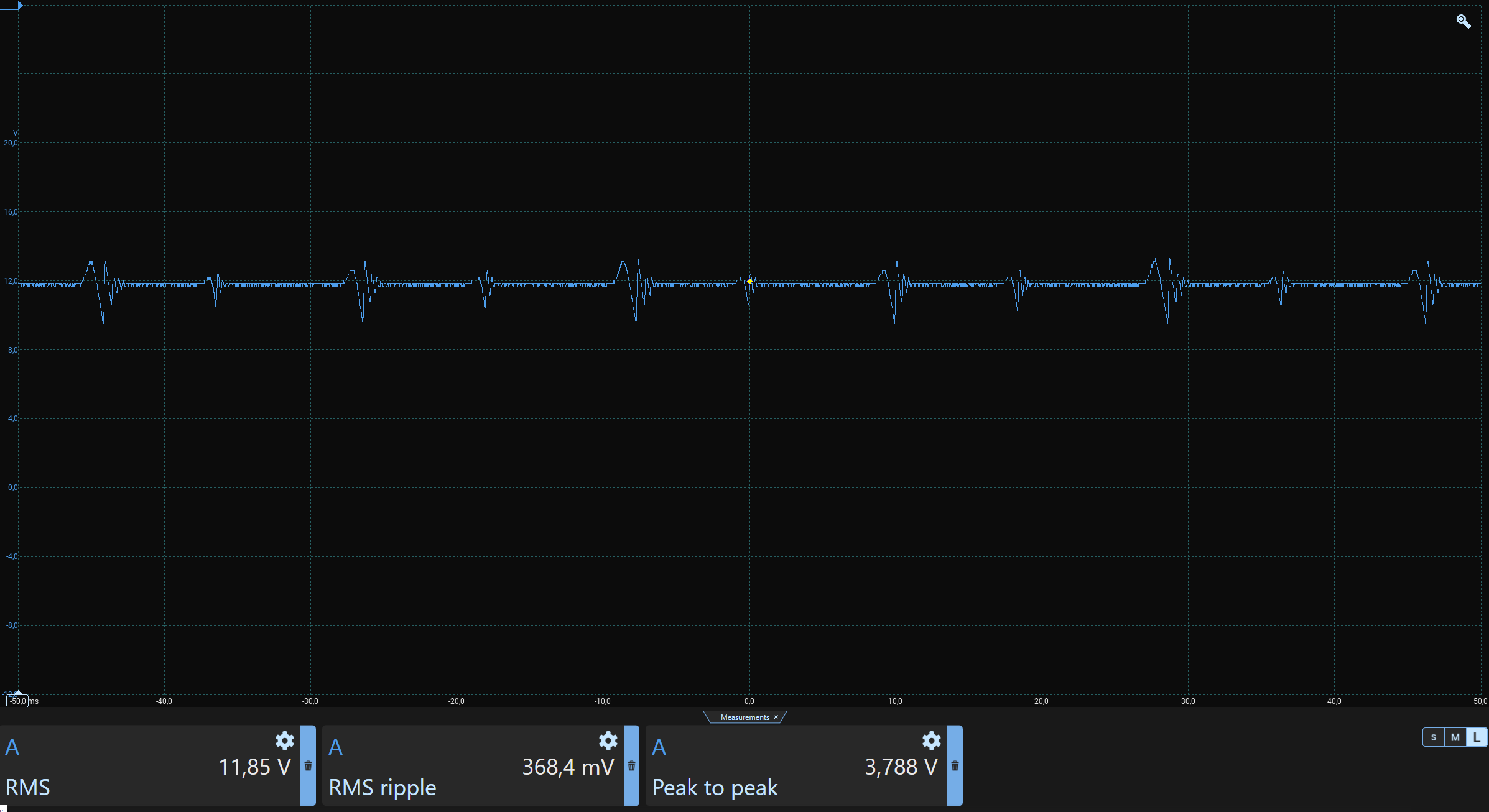 A look at the output shows a steady 11.85V for most of the time. The fan is an inductive load causing these sudden spikes. Though they aren't small the RMS is still stable enough for the fan to still go full speed. The power supply i connected indicates the circuit consumed just under 300mA. So it seems like it would work even on a old-fashioned 500mA USB port. I call that an early success!!
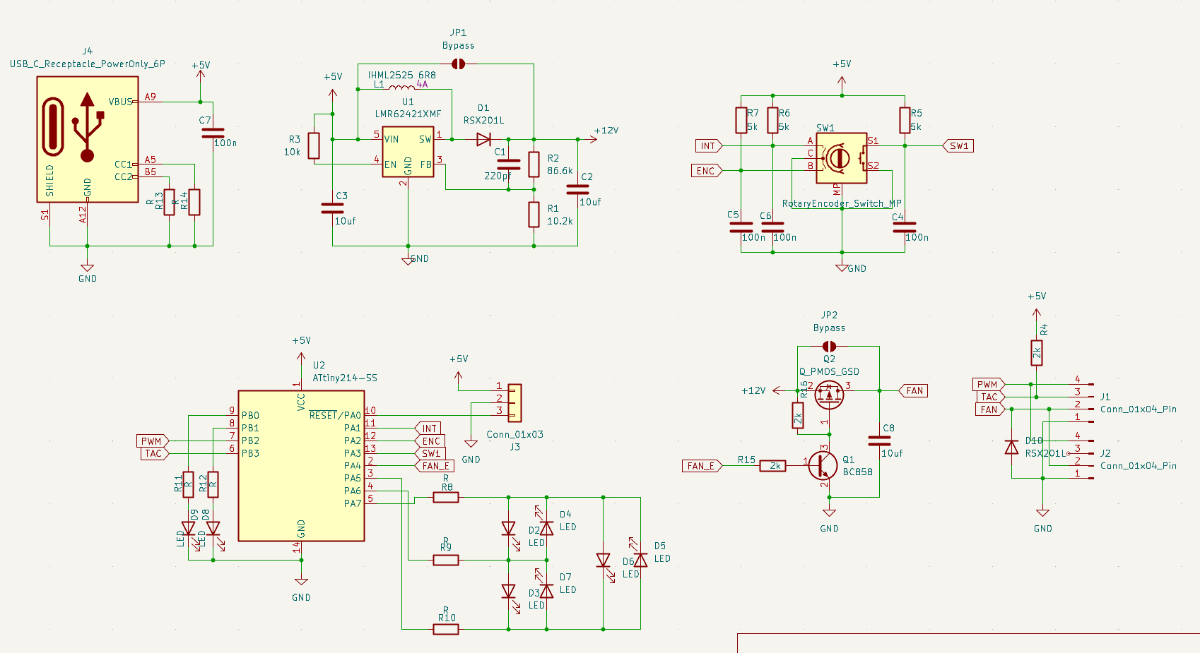
 Rue Mohr
 CLo
CLo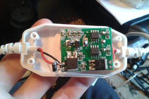
 Arya
Arya
 ZenVega