 FoxHood
I had ordered my boards last week and soldered them. Just In time for a 32 degree heatwave.
I was also a fool and forgot to order the resistors. So i ended up approximating 12V by using a 13K R1 and two 220k stacked ontop of eachother for R2 to get a close enough result (11.8V). Going to have to recalculate it anyway for like 12.1V. You'd be surprised how much those few hundred millivolt matter for these fans.
Right now the Controller is blank and i used the Jumper to skip the load switch. The board is essentially just the boost converter atm. Without a PWM signal any fan should just go full-speed.
Multimeter shows a correct 11.8V so i connected a fan for testing along with an Picoscope. The fan is a standard 120mm Noctua Redux 1700 fan which should do well as indicator for an "Average" fan
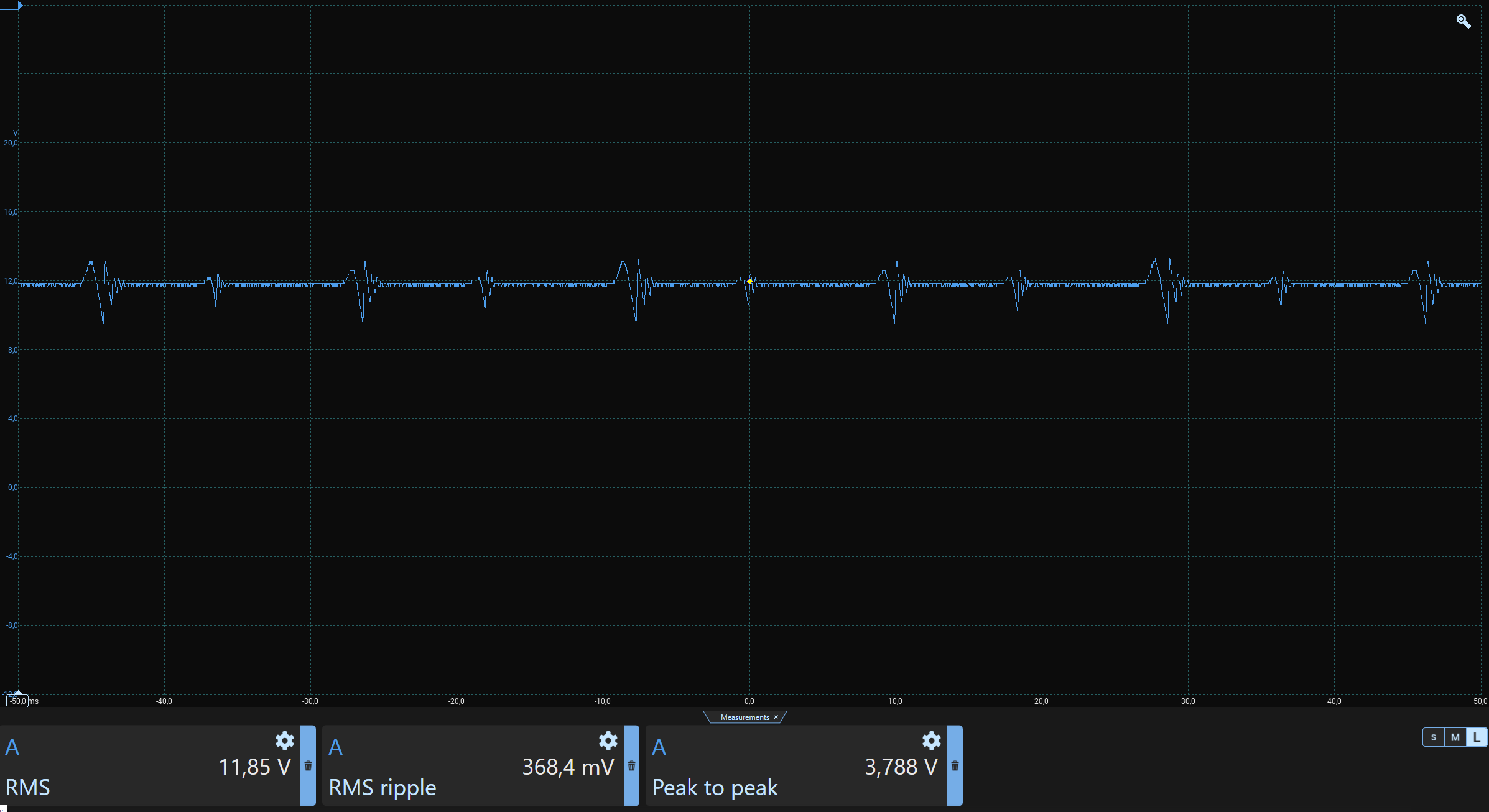 A look at the output shows a steady 11.85V for most of the time. The fan is an inductive load causing these sudden spikes. Though they aren't small the RMS is still stable enough for the fan to still go full speed. The power supply i connected indicates the circuit consumed just under 300mA. So it seems like it would work even on a old-fashioned 500mA USB port. I call that an early success!!
Also quite impressed with the LMR62421. These modern high-frequency Switching regulators are really good, dirt-cheap and with such a tiny footprint too!! If the step-down sibling also proves to work i'll be looking at cutting out 7805 compatible regulator modules out of every project i have. Those are so expensive....
Anyway. This means i can start work on getting the controller in order. Already tested out the theory on a different AVR chip, but i gotta migrate it over to this one. Will want to retest once the load switch is in-line with the load and maybe experiment with an extra capacitor to see if the spikes can be somewhat muffled with extra capacitance to take the hit.
Discussions
Become a Hackaday.io Member
Create an account to leave a comment. Already have an account? Log In.