 FoxHood
Version one is fairly simple. Circuit has 6 parts: Receptacle, Booster, Load-switch, Encoder, Output and Microcontroller.
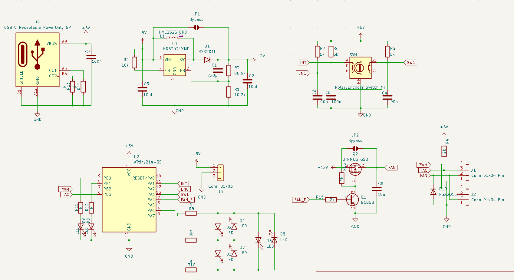
Receptacle:
The receptacle is a common 6P Power-Only USB-C port (USB4125). With a set of 5.1K resistors to signal to a USB-C Supply that it is downstream device.
Booster:
The Booster is made with a Texas Instruments LMR62421 switching controller. This is a tiny, cheap little booster that can convert 5V to 12V. Being SOT-23-5 renders it easy to hand-solder.
Since there are 5V Fans out there and i like my designs Flexible: A solder jumper is placed that can bypass the entire booster.
Load-Switch
Not all fans shut-down at 0% PWM, for these a way to shut the fan off is needed. Originally i thought about using the Boost Converter's EN pin, but that wouldn't really shut output down as much as just let the 5V pass through the Inductor and Diode. Powering the fan with ~4.5V. So a full switch was needed.
The Switch is a standard High-Side FET switch. The FET i used is a PMV50EPEAR that can switch about 4A. Though any SOT-23 Power Pfet with a GSD pin order should work here.
A Solder Jumper is available to cut out the switch in its entirety. Be it due to lacking components or running without a controller as just a dumb 12V supply.
Encoder
A standard Bourns EC12R-S encoder will provide input. Components around it are chosen according to recommended design in datasheet.
Rotating will manipulate the speed. Pressing it will toggle the controller on/off
Output:
Output is mostly just a pair of specific Molex 47053-1000 headers, commonly known as PWM Fan Headers (idk what it is with brands like Wurth and Molex insisting on these obtuse numbered names...). Although they allow for 2 fans to be connected. They both have the same PWM signal and only the top one has its Tachometer connected to the Controller. This effectively is the same as using a Splitter cable
A reverse polarity shunt diode is placed just in case. These fans are inductive loads after all.
Controller
Actual Brains is going to be a Microchip ATTiny414. AVR chips may have gone out of style a little over the years as ARM and RISC-V have spread. But for small jobs like these you just can't beat the reliability.
This is going to be my first time dealing with a newer "tinyAVR 1-Series" chip. Used to the old ATMega8 and the ATTiny2313. Supposedly these newer chips don't need external resonators anymore to get to 16Mhz and have far greater flexibility when it comes to IO interrupts. Going to be a fun experience in figuring these out and trying out the Serial UPDI feature of AVRdude to program them. Do like how these days just 3-pins are needed for programming.
For indicating set speed i opted for a whole bunch of leds in a Charlie-Plexing setup. To get the most out of the IO-Pins. With a quick pair of regular connected diodes for Status (Turned off and Fan-Detected)
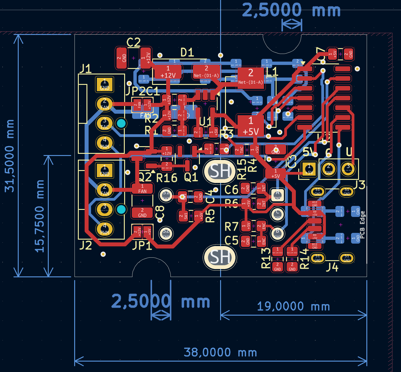
The real challenge was cramming it all. I think i managed to do a decent job.
Being one of my first KiCad designs it took a little to figure out symbols, footprint and IO, but once i got going it went really quick. KiCad feels way more expedient than Eagle. Especially with how many footprints it already knows. Some footprints like the USB4125 i quickly modified to have longer pads for hand-soldering. That KiCad lets me do that quickly in a design and only for that design is a godsend.
Discussions
Become a Hackaday.io Member
Create an account to leave a comment. Already have an account? Log In.