-
1Power Module Assembly
![]()
![]()
![]()
![]()
![]()
![]()
![]()
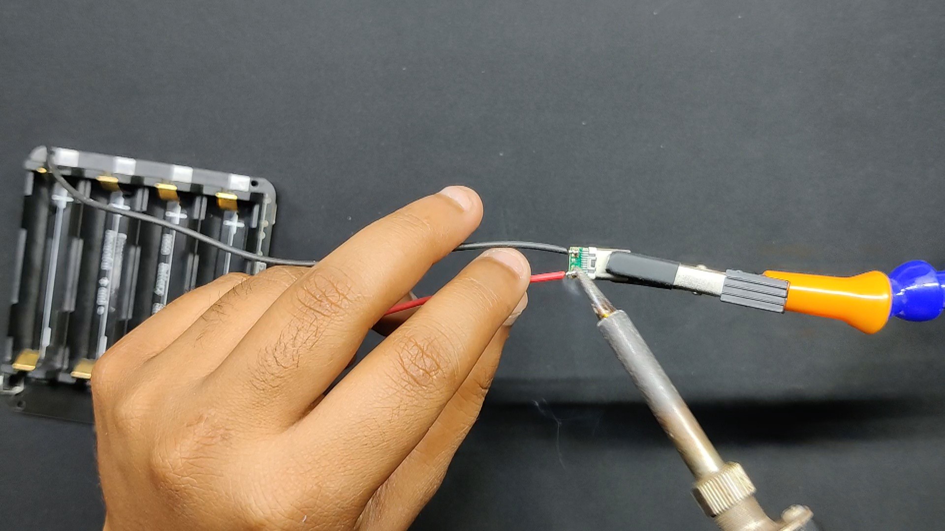
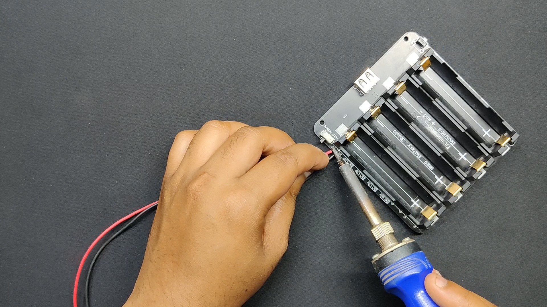
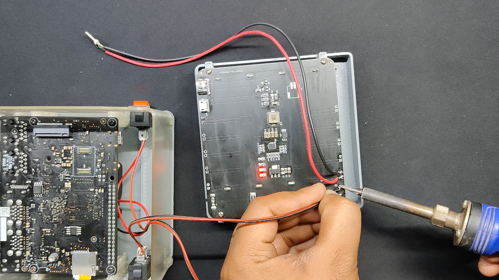
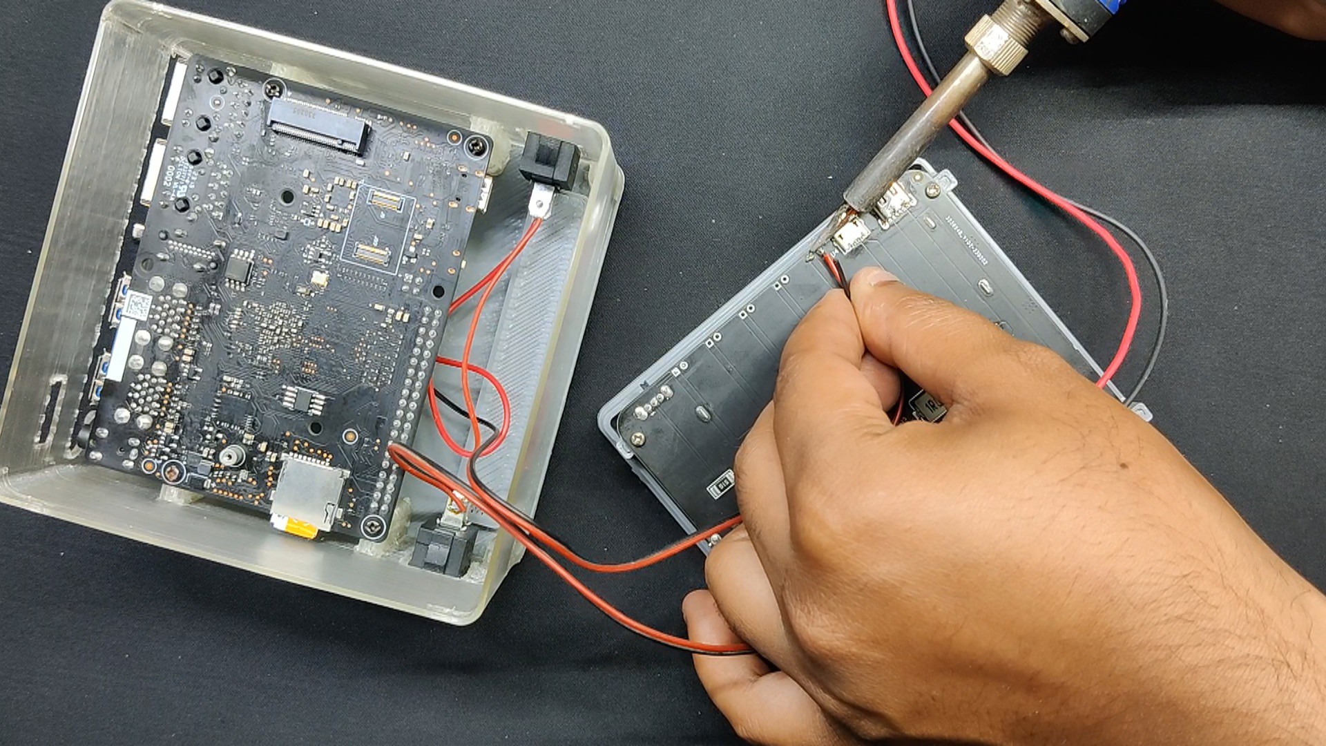
- We connected red and black wires to the Type C Breakout board's VCC and GND ports using a soldering iron. We then connected the red and black wires to the power module's 5V and GND.
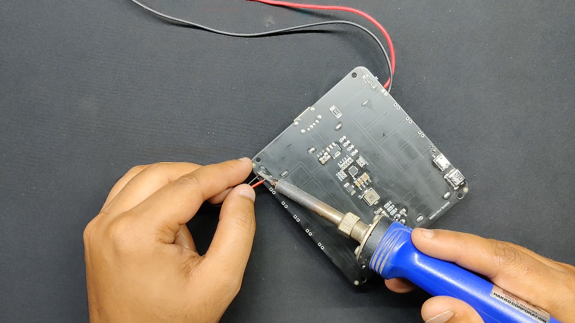
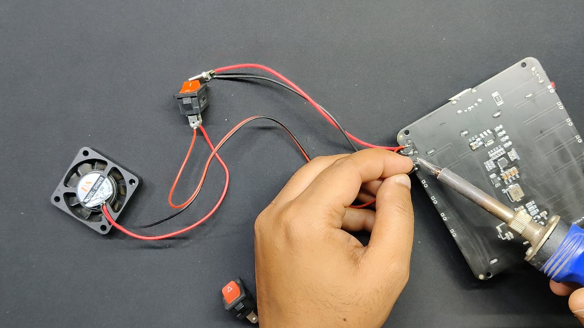
- We additionally upgraded the push button's terminals on the board with a bell-style rocker switch. We linked the Rocker switch to the terminals of the existing PSU button so that it could be used to turn the power module on or off.
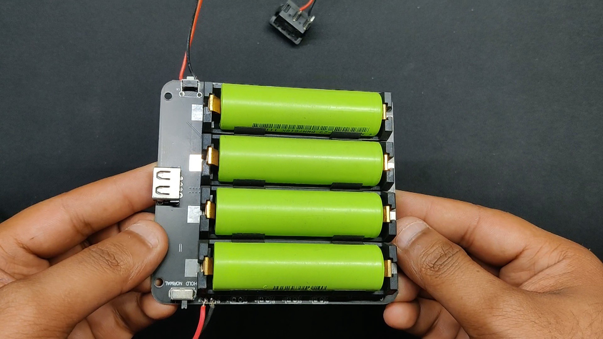
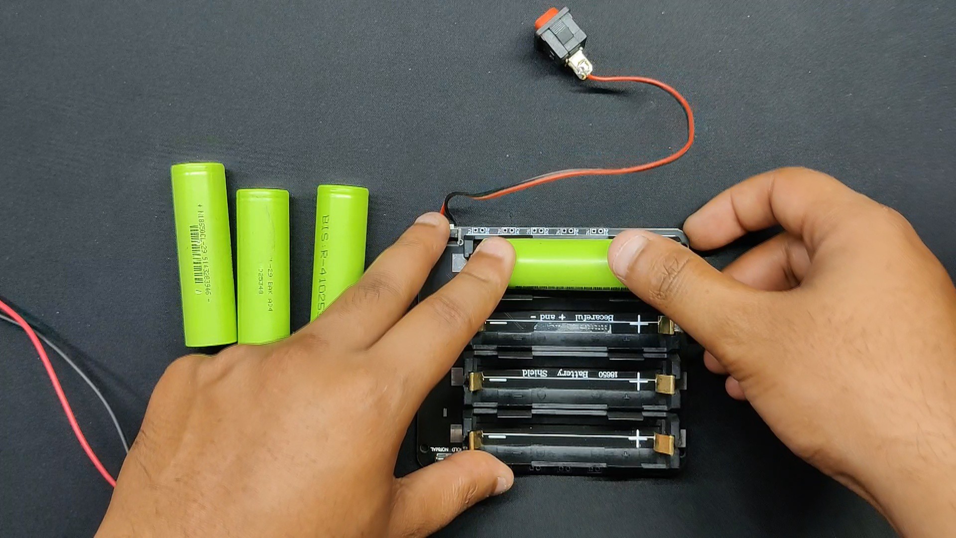
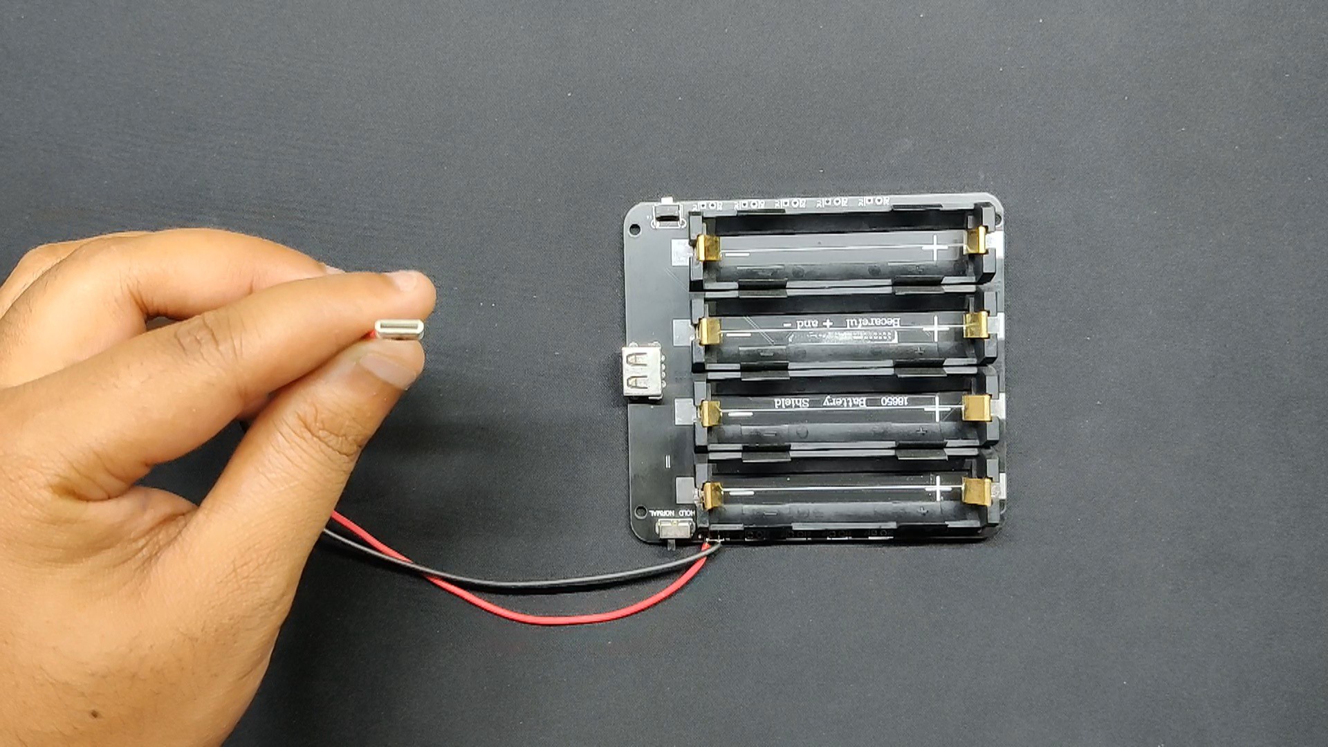
- Subsequently, we inserted four 3.7V 2900mAh Li-ion batteries into the cell holder located on the rear side of the power module, taking care to align the cells with the designated polarity on the board. Incorrect cell placement will undoubtedly result in a short circuit.
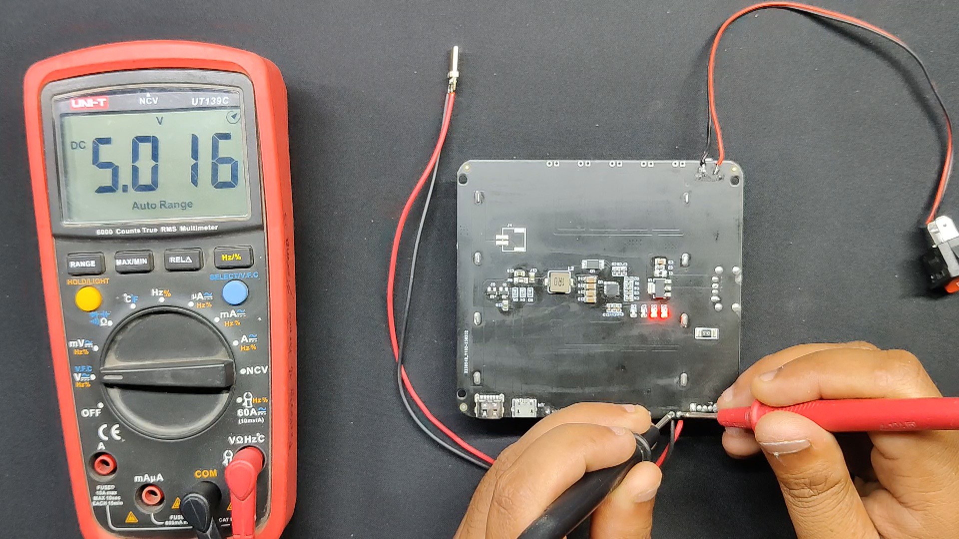
- Following the placement of the cell, we use a multimeter to measure the output voltage by switching the rocker switch. 5V is seen on the output side, confirming that the setup is operating.
-
2Cooling Fan
![]()
![]()
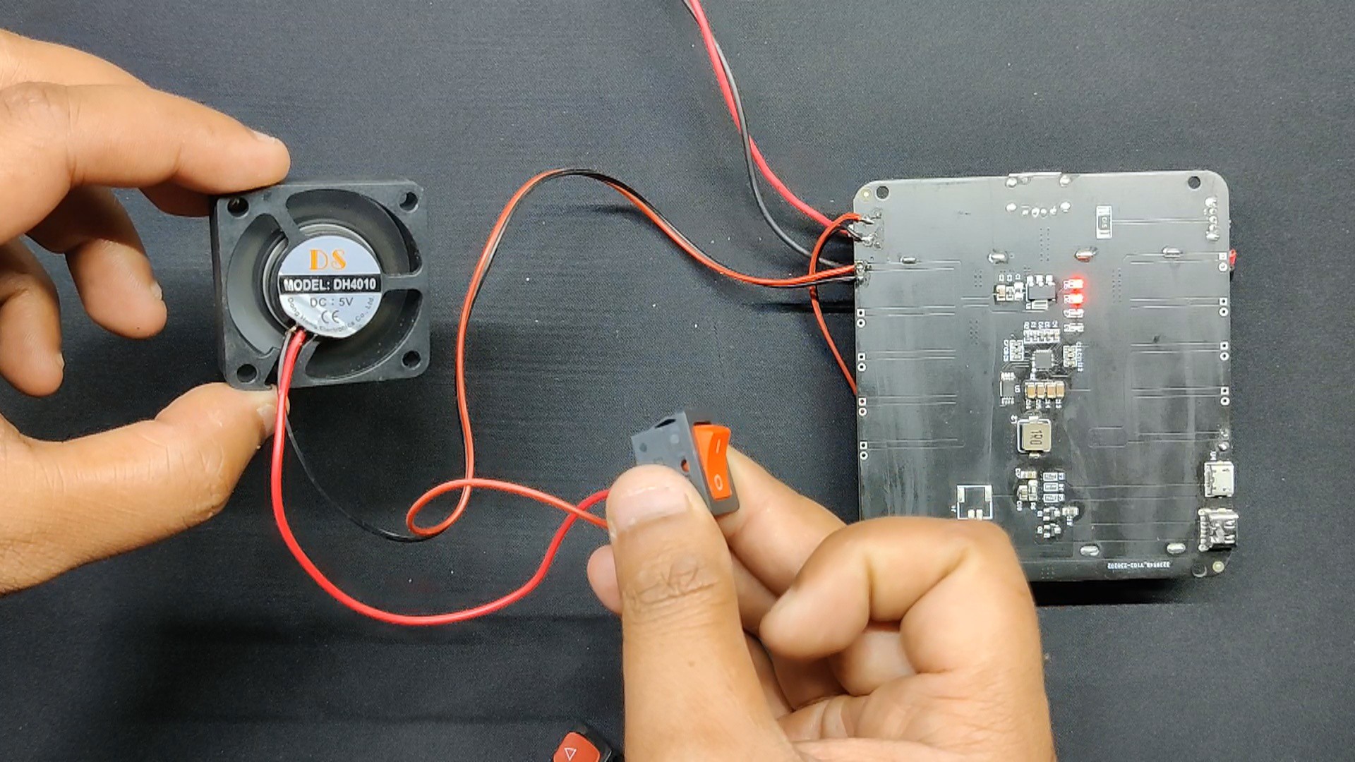
- We connected a 5V mini PC fan to the module's 5V output by placing a rocker switch between the fan's 5V and the power module's 5V.
- The user can turn the DC fan on or off by using the rocker switch.
-
3Top Lid Fan Assembly
![]()
![]()
![]()
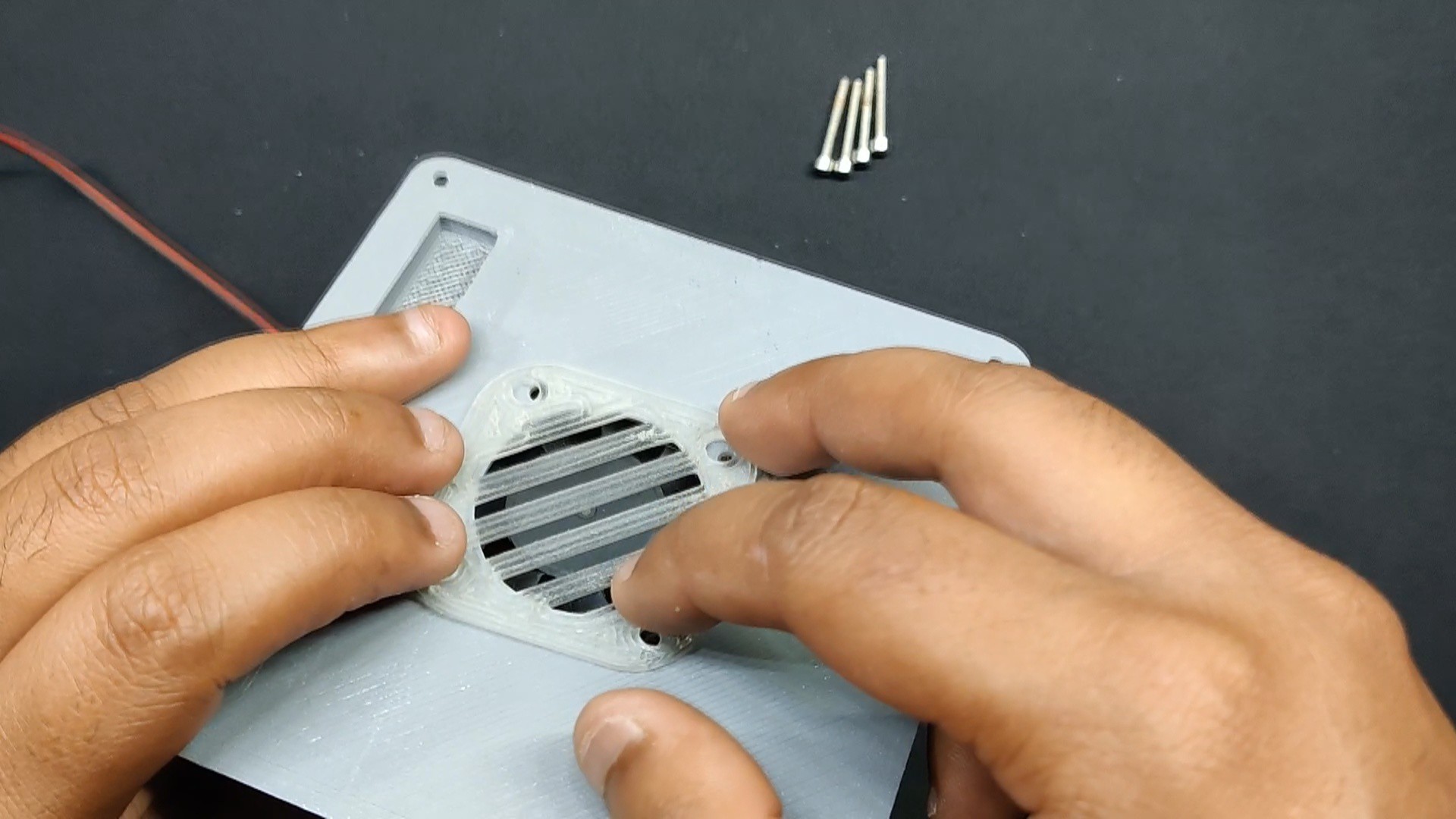
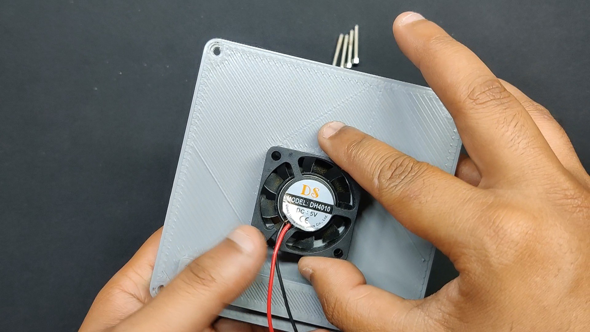
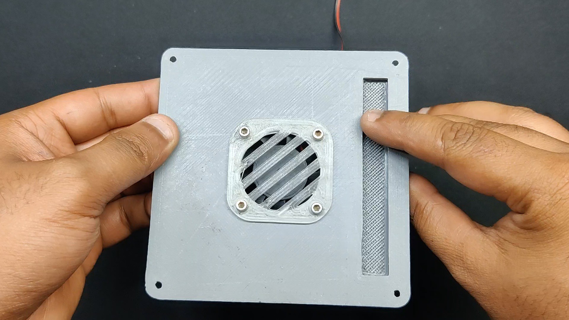
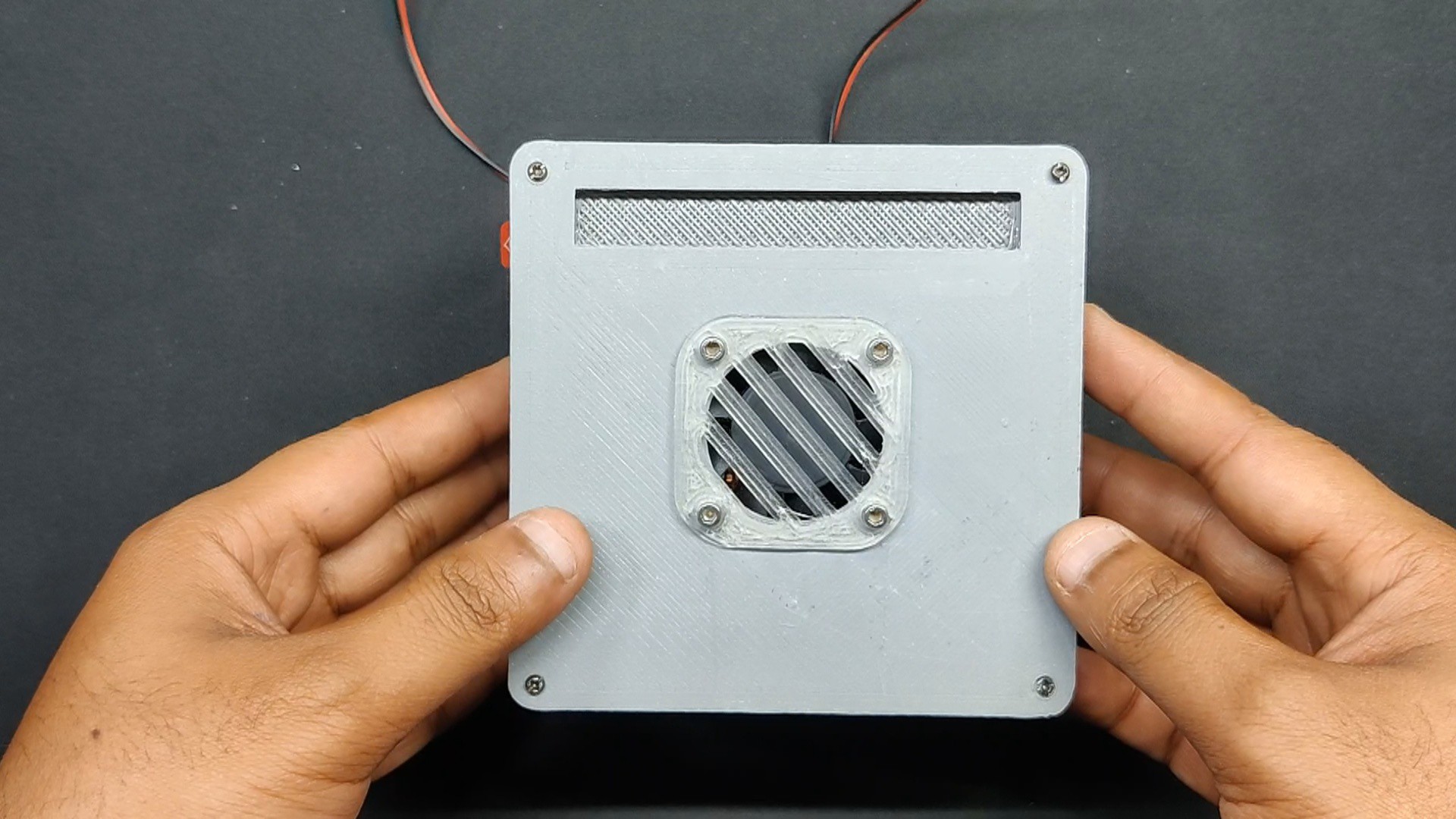
- We installed the DC fan and fan grill on the top lid part, which holds the fan in place.
- next, we used four M3 Allen key type bolts and nuts to fasten the fan to the top lid part.
-
4Middle Section Assembly
![]()
![]()
![]()
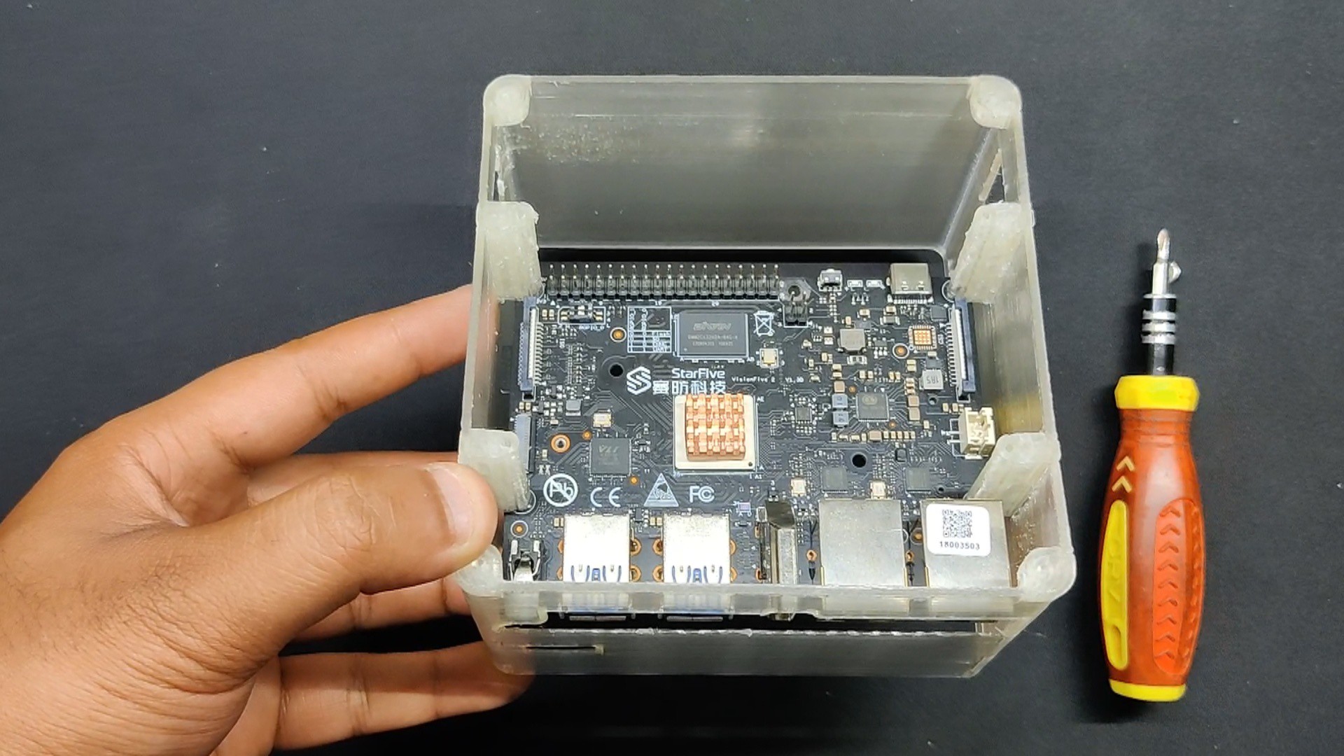
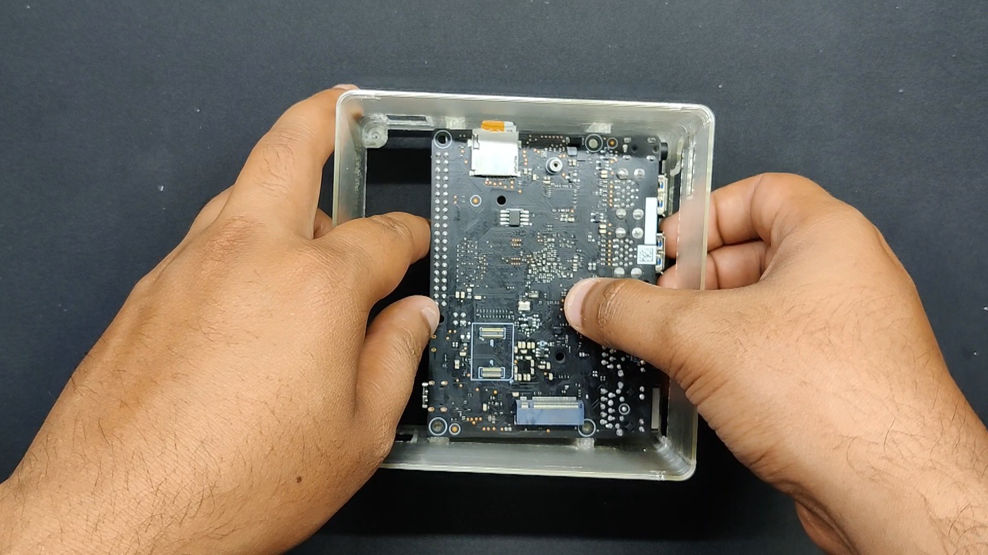
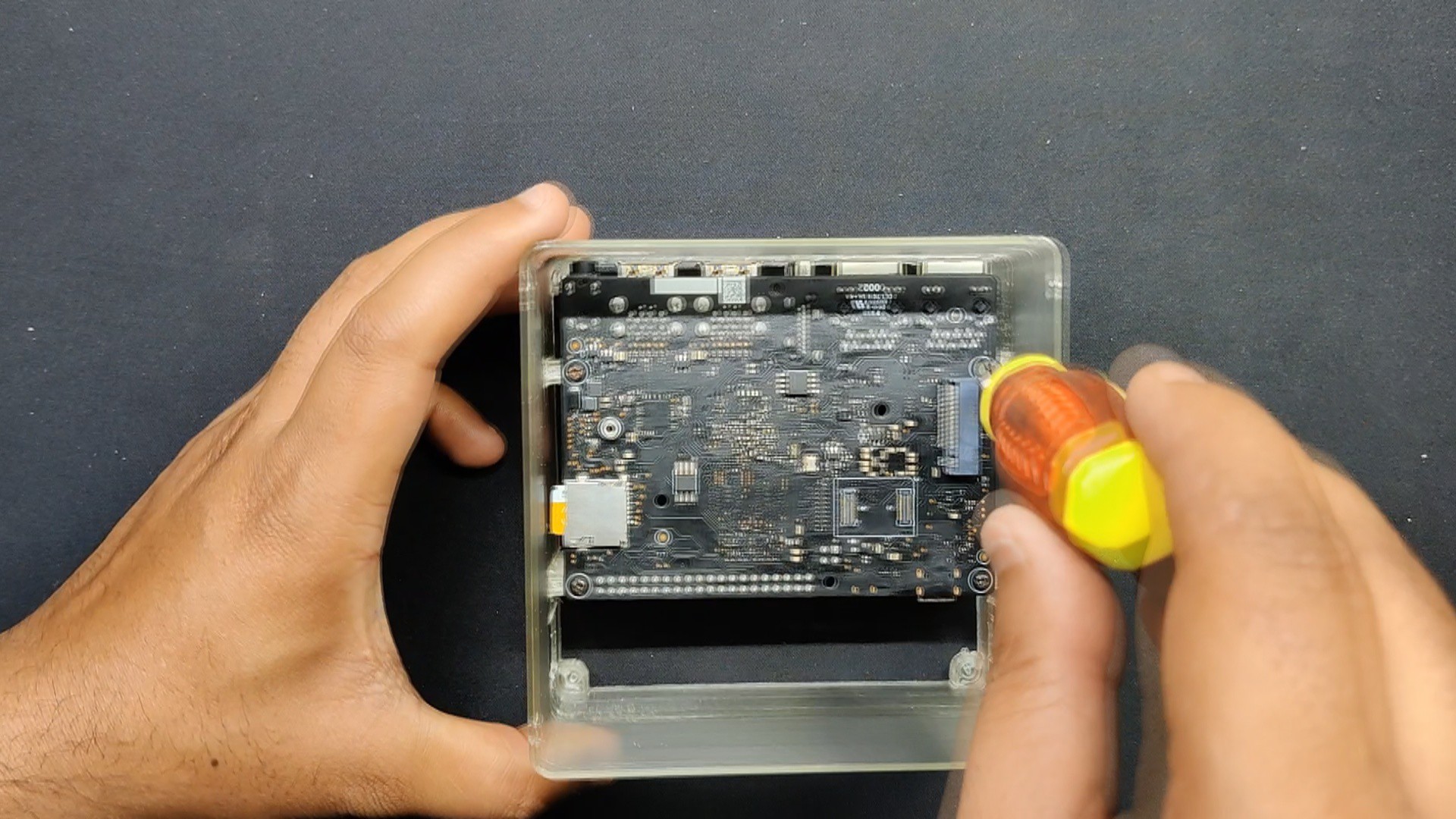
The assembly of the mid section was quite easy: we just needed to insert the SBC into the upside-down orientation and use four M2 screws to fasten it to the mid section using the provided screw bosses
-
5Switch Assembly
![]()
![]()
![]()
![]()
![]()
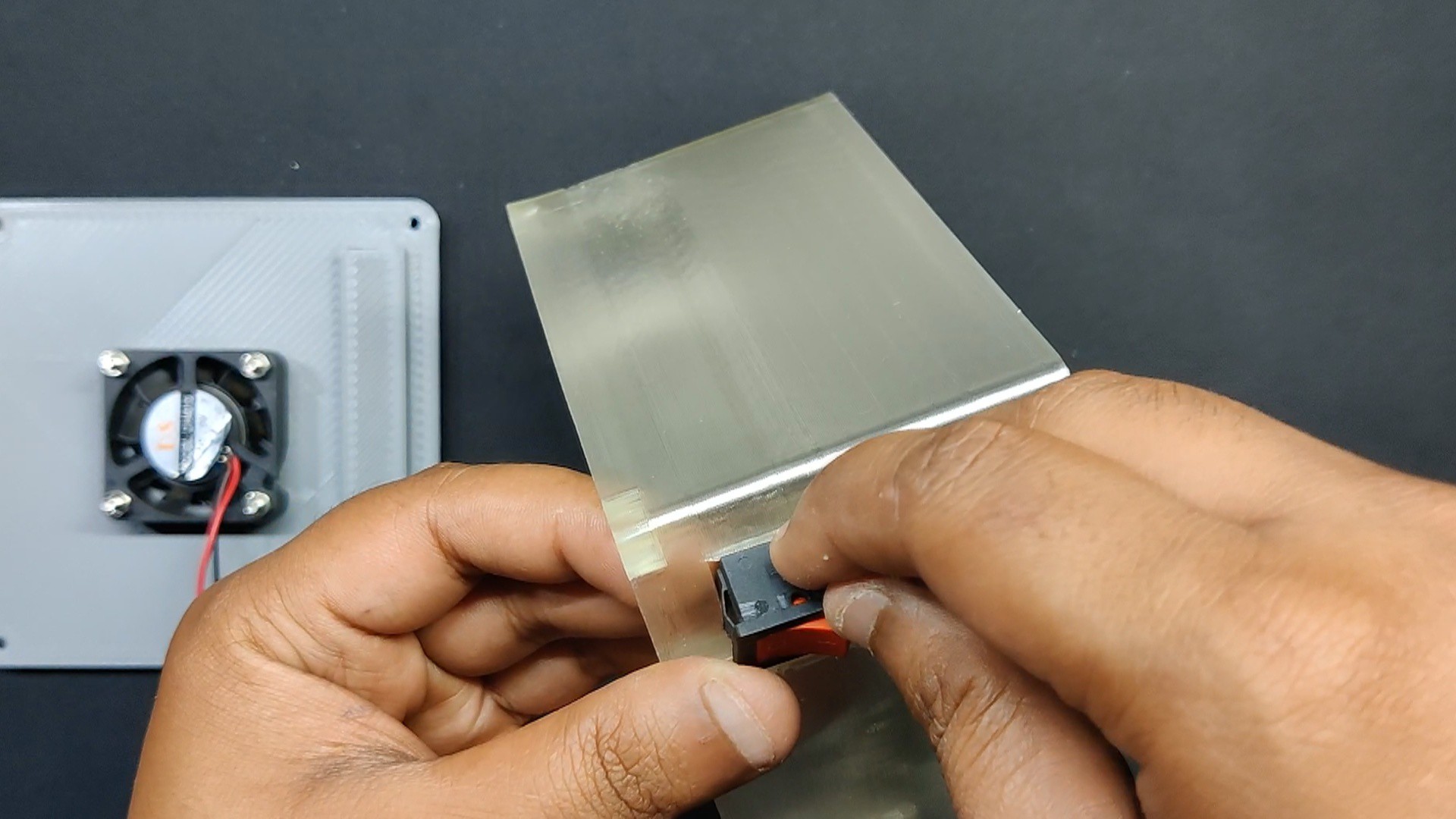
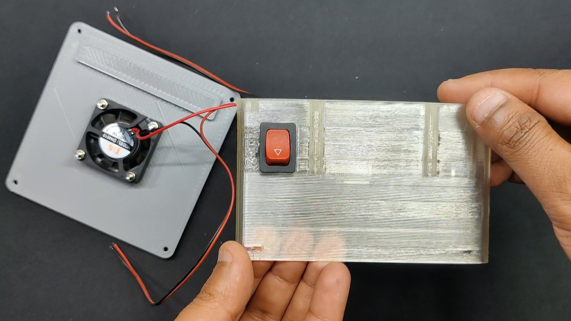
- After removing the switch that is attached to the DC fan, we install it in the switch slot located on the left side of the midsection.
- Next, we reattach the DC fan switch to the switch.
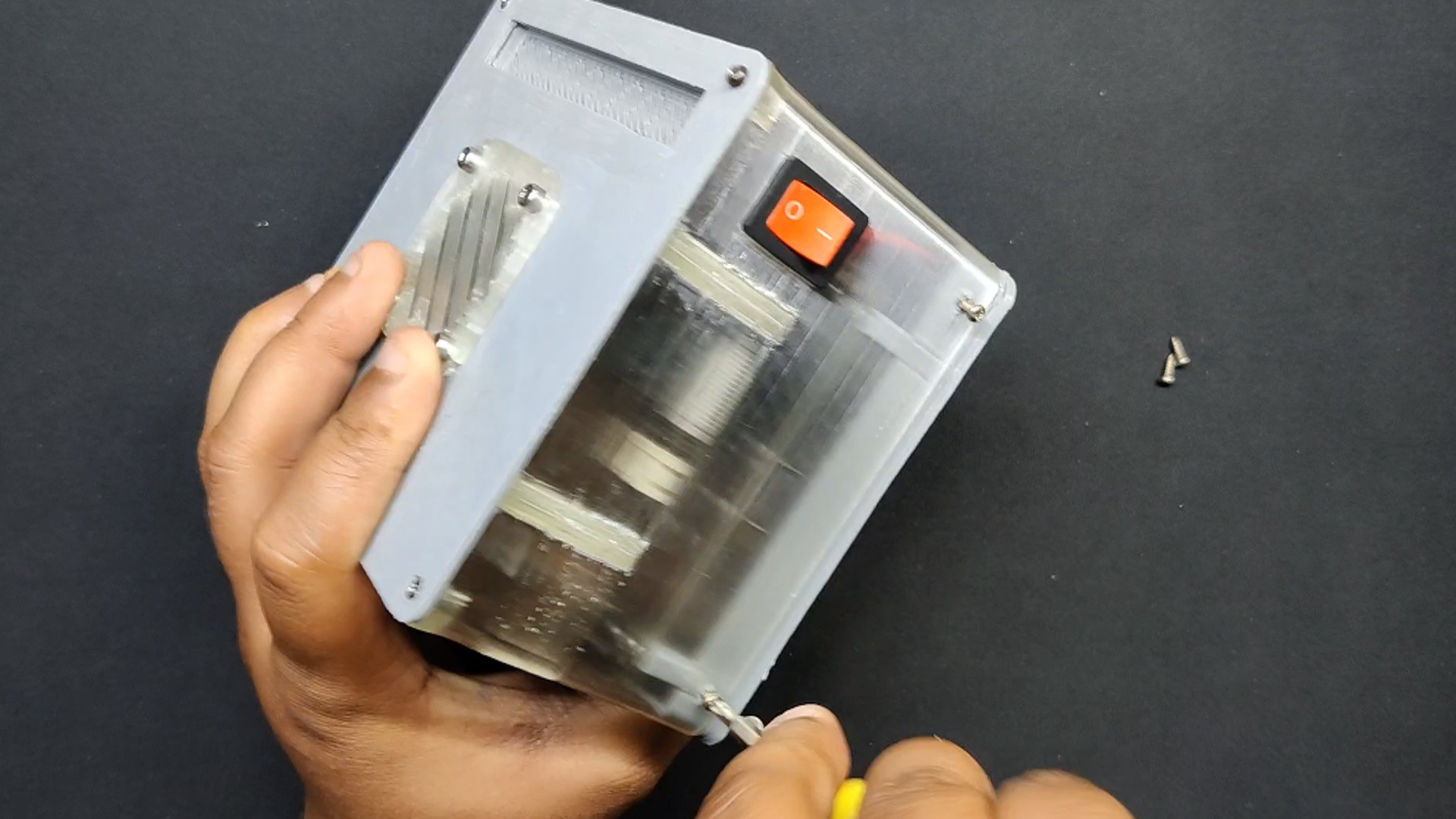
- In the same manner, we installed a bell-shaped rocker switch on the center section's right face, which will serve as the primary power-on switch.
-
6Final Assembly
![]()
![]()
![]()
![]()
![]()
![]()
![]()
![]()
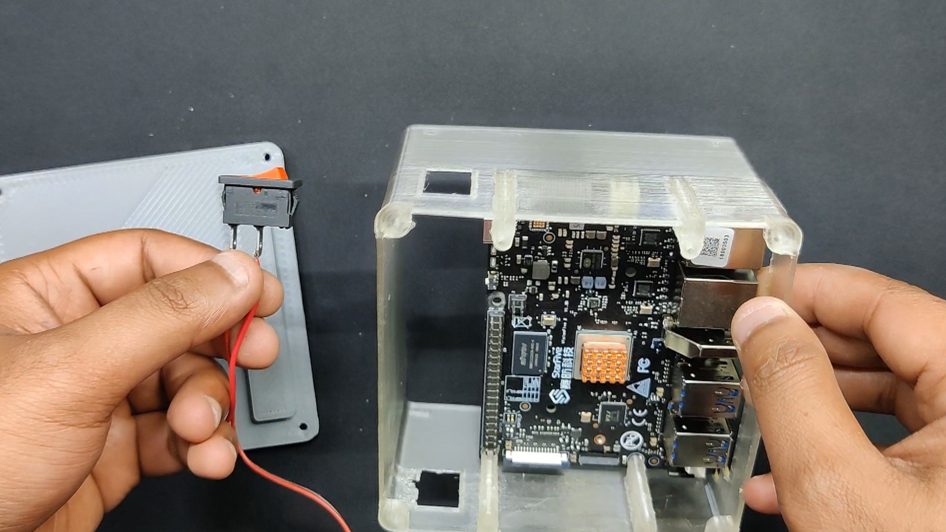
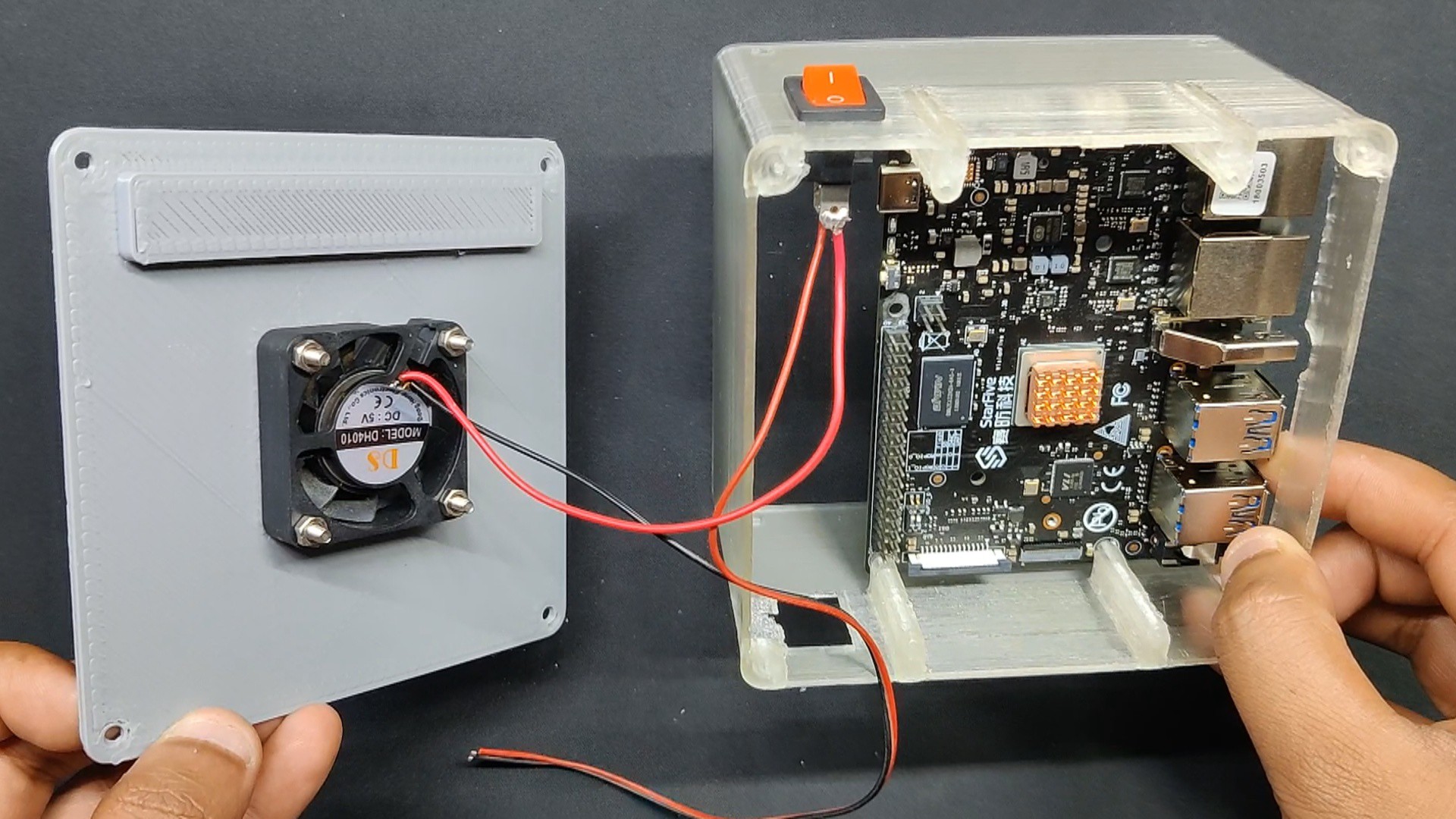
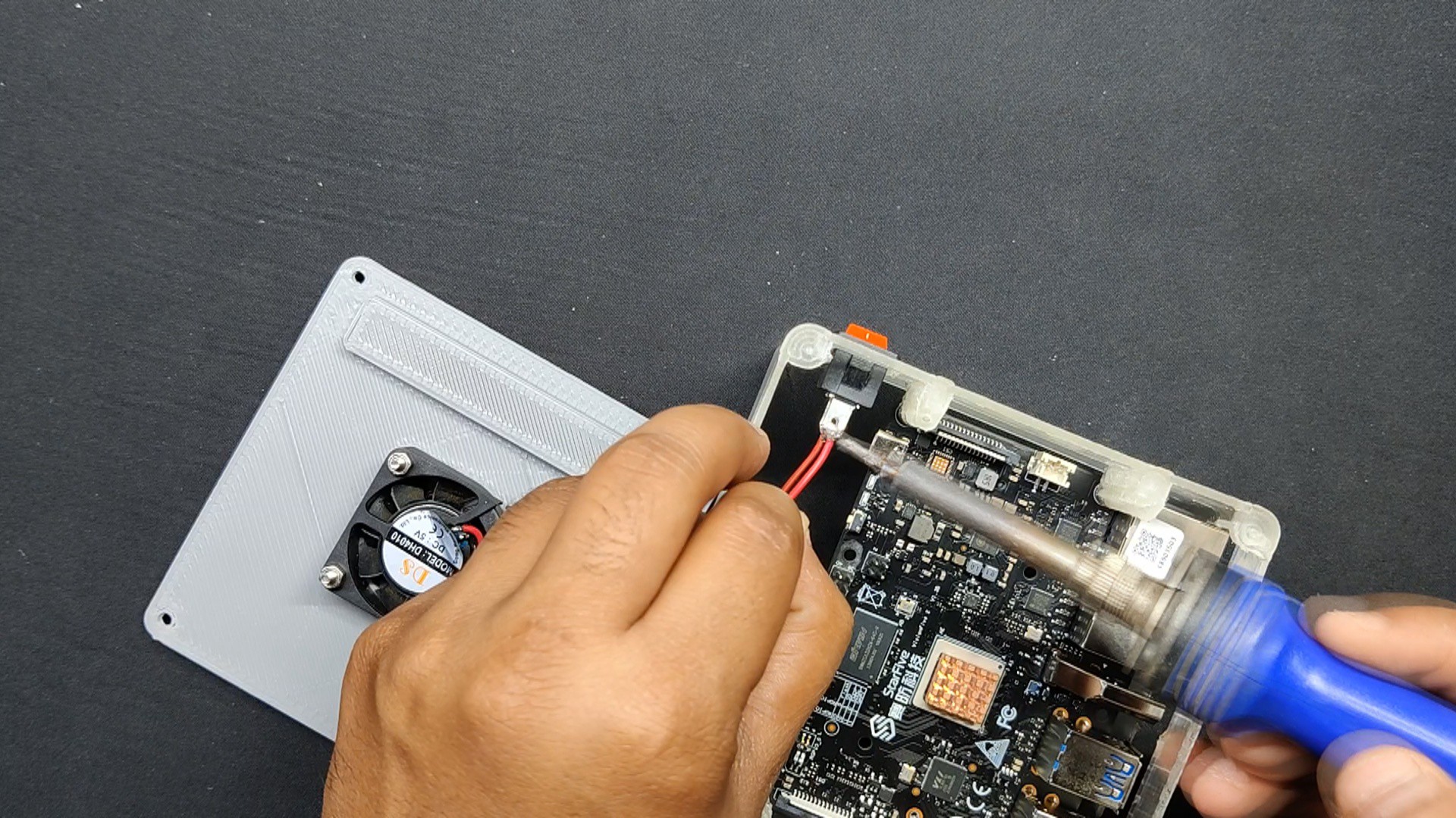
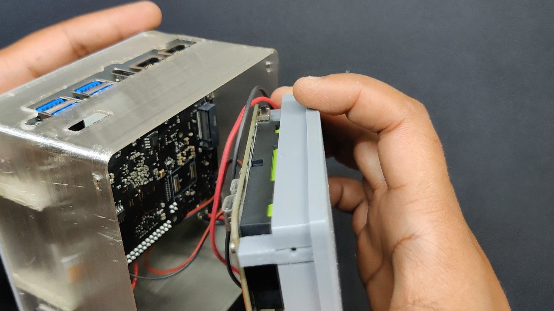
- The assembly process begins with the wires of the Power ON/OFF rocker switch being soldered in parallel with the ON/OFF switch terminals that are positioned onboard.
- Likewise, we linked the DC fan's terminals to the power module's 5V and GND.
- After adding the power module, the Type C Port on the Starfive board is connected to it. Power for the SBC will be supplied by this port.
- The midsection and the bottom lid were then linked together, and four M2 screws were used to permanently fasten them together.
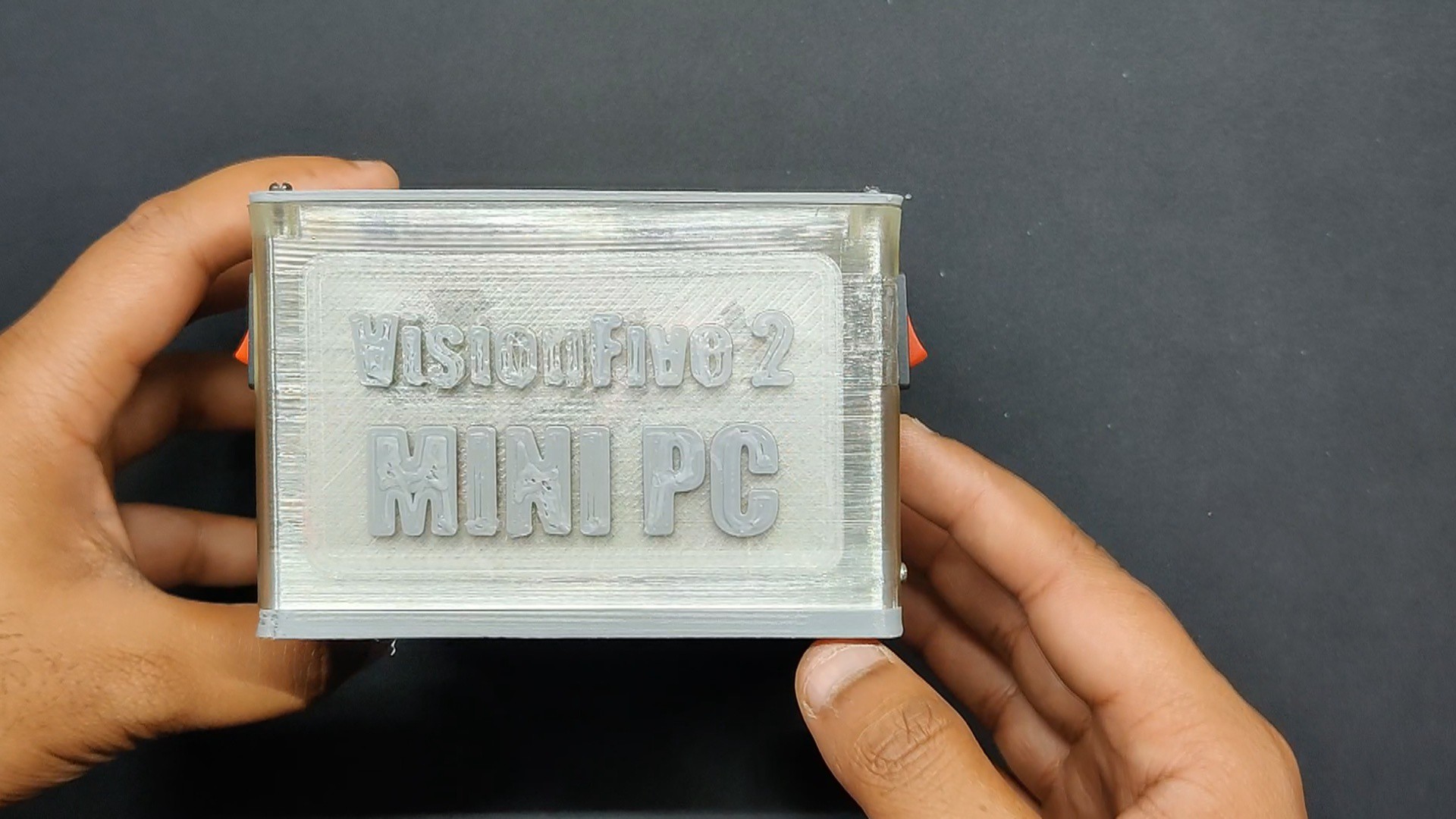
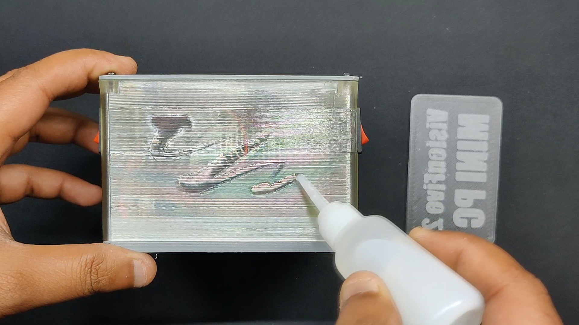
- We attach the SBC Nametag on the front face of the Mid Section using Superglue.
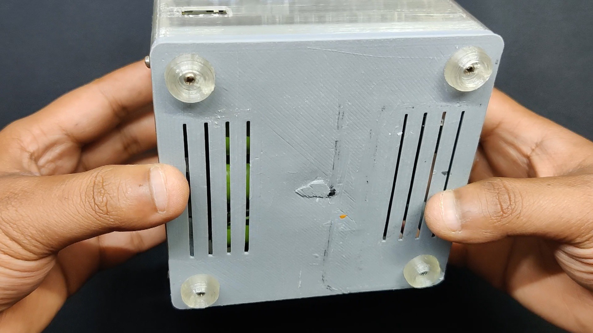
- Finally, we install the model's four feet and fasten them with four M2 screws to the bottom lid.
The Assembly Process is now completed.
-
7Results
![]()
![]()
![]()
![]()
![]()
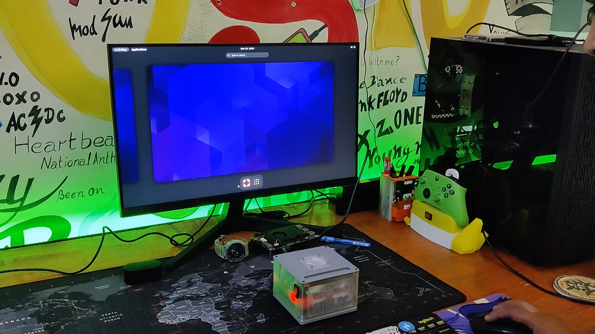
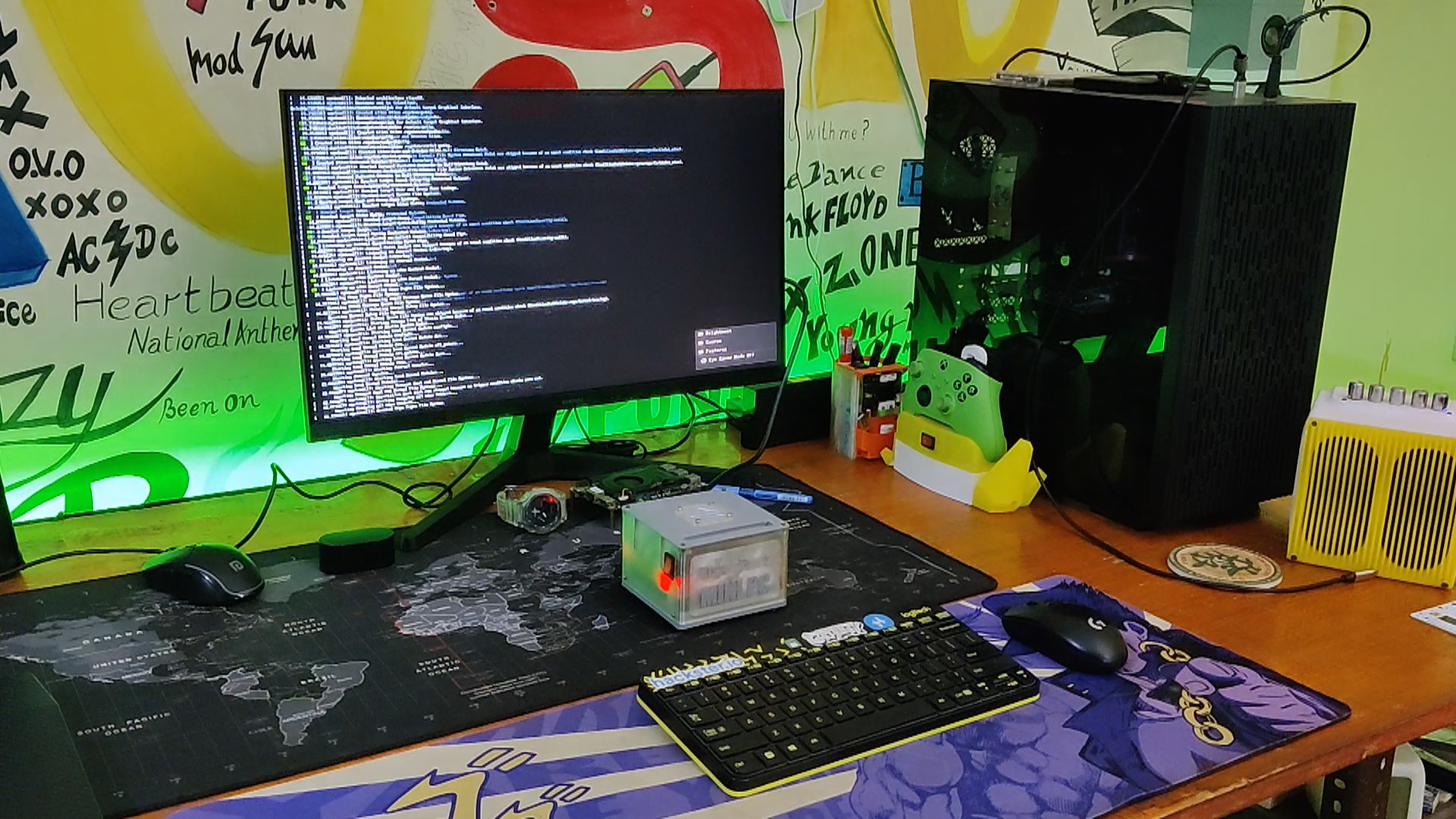
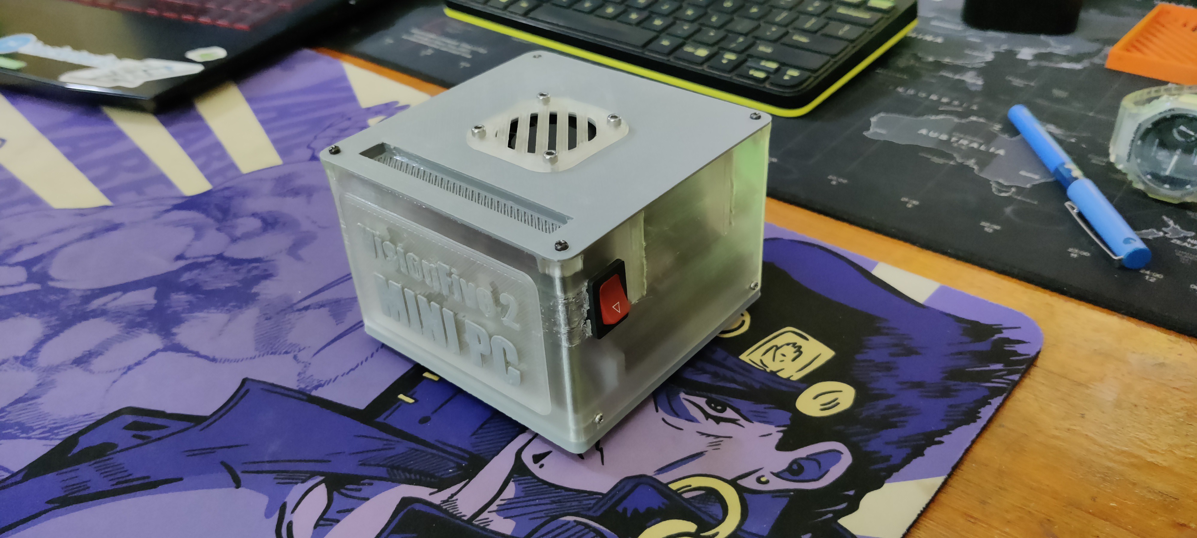
This straightforward build resulted in a functioning RISC-V PC with onboard power, driven by the new Starfive VisionFive 2 board.
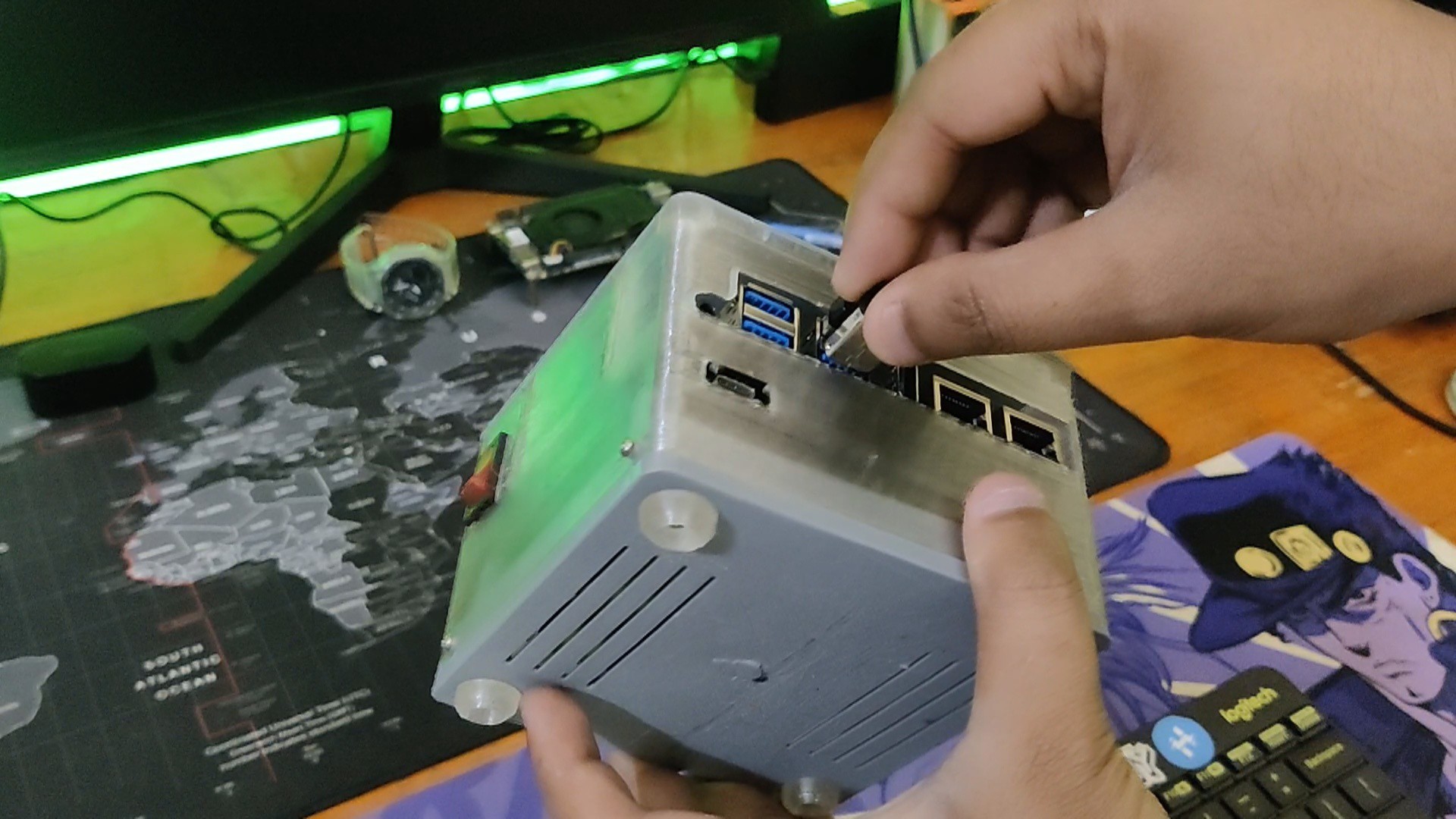
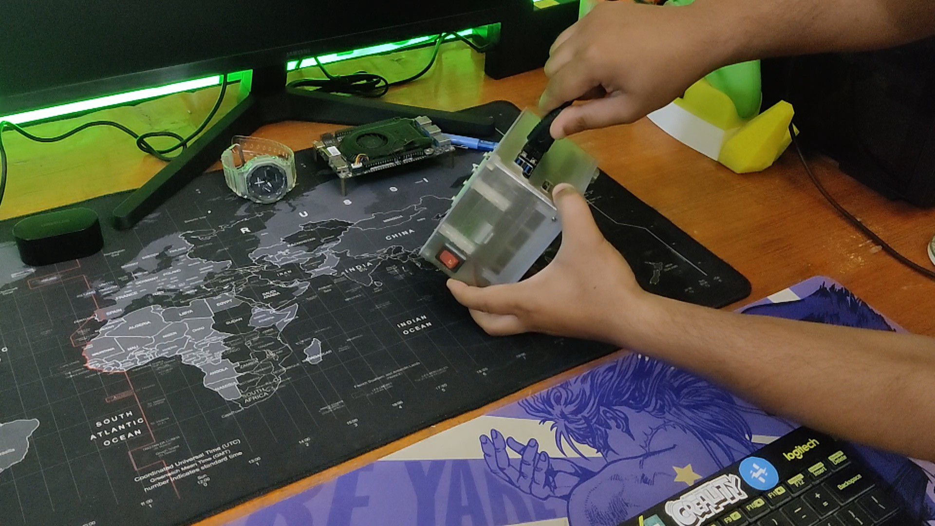
In order to get started operating the Mini PC, we connected a monitor via the HDMI port and added a mouse and keyboard via the USB ports.
Once the Power ON OFF rocker button is pressed, the mini PC powers on. We then turn on the cooling fan to ensure that the CPU temperature stays low.
The SBC has Debian installed, and we will test the VisionFive 2 SBC using this PC setup and compare it to the current arm-based board.
For now, the objective has been completed, which was to make a small PC setup.Overall, this project was a success and needs no further revisions.
Thanks for reaching this far and I will be back with a new project pretty soon.
Peace.
 Arnov Sharma
Discussions
Become a Hackaday.io Member
Create an account to leave a comment. Already have an account? Log In.