0%
0%
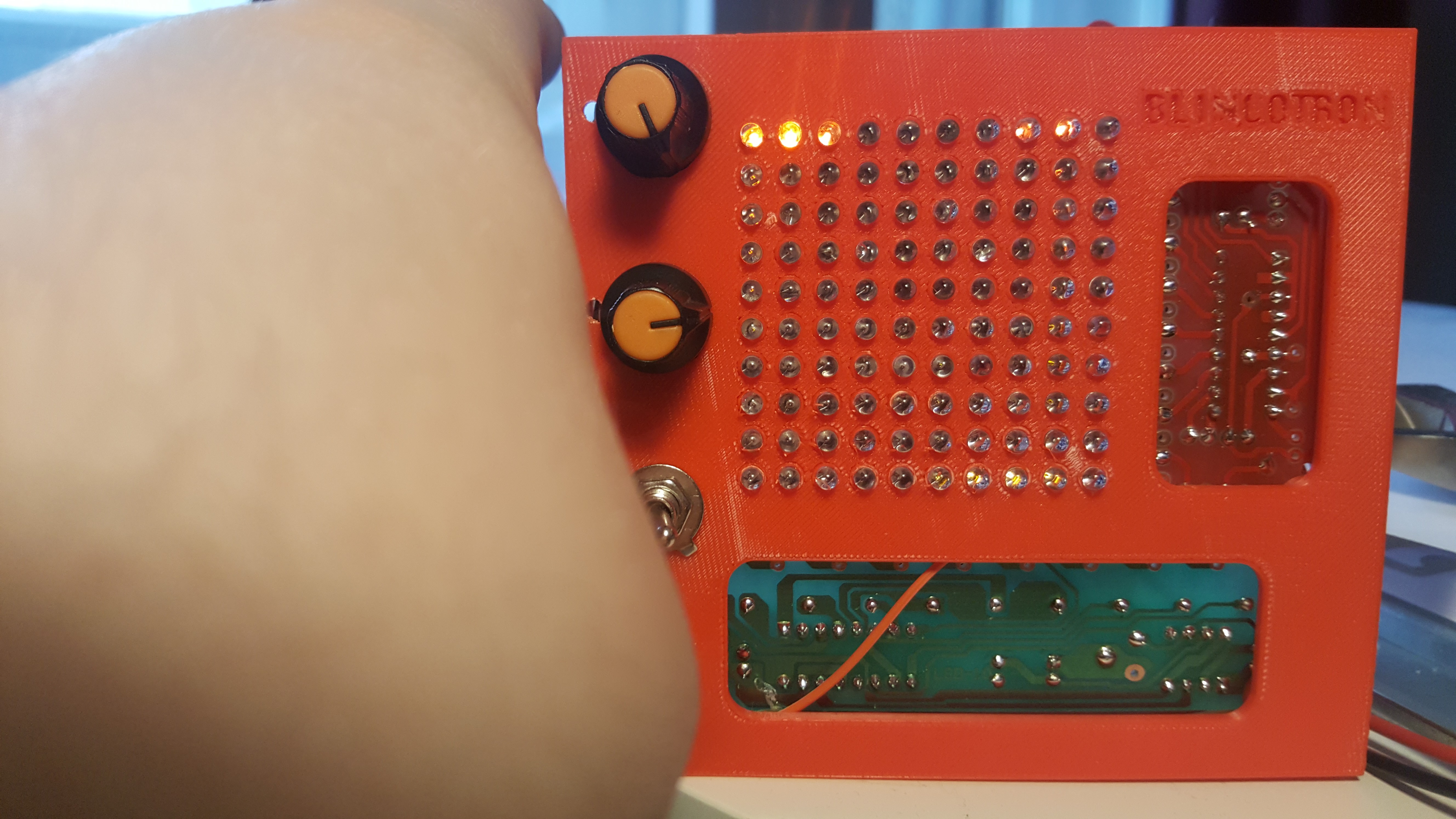
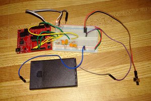
RGB LED Oscilloscope
using cheap eBay kits, some cheap eBay RGB LEDs to make an LED oscilloscope (inspired by Ted Yapos - LED Oscilloscope Mk. II)
 davedarko
Become a Hackaday.io member
Already have an account? Log in.
Just one more thing
To make the experience fit your profile, pick a username and tell us what interests you.
Pick an awesome username
hackaday.io/
Your profile's URL: hackaday.io/username. Max 25 alphanumeric characters.
Pick a few interests
Projects that share your interests
People that share your interests


 Petri Varsa
 Mikhail Svarichevsky
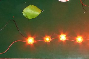
 Joseph Eoff
RGB LEDs? Are you going to make dual (or triple) trace version?