moosepr
-
None Standard Standard
10/21/2024 at 12:47 • 0 commentsIm not a massive fan of using standard connectors for non standard uses. Any company that makes a device that uses usb-c to charge a device, but with unchecked 12v in there needs locking up!!
Using standard connectors does of course have many advantages. They are generally cheap and easy to source, and normally have great connector density allowing you to have lots of connections in a small space.
When I originally had the idea for CL-32 i had though of using an M2 socket for the connection of additional functionality. The non standard usage always put me off, and I wanted to keep the components on the one side of the board to keep manufacturing costs down. This lead me to use the reverse entry headers that were on my design.
Looking for parts for the board made me realize that its not always clear which headers are designed for bottom entry, and my past experience with surface mount headers hasnt been great. They are only held onto the board by the strength of the bond between the copper and the pcb. If the usage of this device is going to be in an educational setting, then I can see headers being ripped off regularly
Magnets? How do they work?
One of the comments on the project suggested looking at magnetic connectors. These would solve the heavy handed user problem, and the polarization of the magnets should stop people wedging the board backwards.
There are 16 i/o pins, and 2 power pins, so we would need a larger connector.
Using something like this would possibly fit the bill, but they only come in thru hole mount, making a large portion of the add on board un-usable for adding functionality. So the hunt continued..
M2 popularity
Looking in the tech field, the M2 slot is used a few times by other devices (see sparkfun MicroMod and Sipeed Lichee RV) so its not un-common to see it in non standard settings. I had though I could try and sit as close to a standard spec as possible, with the location of power and data lines, so started looking.
After some digging it actually looked like an E key pin layout actually fits much better than i thought.
The USB connection to the ESP could be piped into the connector theoretically meaning that an old E-key device that worked over USB (modem/gps/etc) could possibly work as long as it was happy wth 3.3v.
The I2C connection would allow the keyboard and RTC I2C connection to also be broken out into the connector, allowing similar connectivity as the USB, and also adding to the available i/o.
The UART connection could allow backup access to the ESP if the normal USB connectivity fails.
The PCI-e pins could then be used for the i/o, keeping things within the "standard" with the location if data pins, and it might even let some crazy people try to talk to PCI-e devices with the ESP.
So the actual pin layout should be safe if there was any crossover in card usage (CL-32 and laptop) but the biggest issue could be voltage. A laptop card is designed to work on 1.8v but my cards will be using 3.3v, so using a CL-32 card in a laptop would be fine, but a laptop card in a CL-32 might let the magic smoke out
Seems like a small enough risk for me...
-
To Be (dis) continued...
10/14/2024 at 16:09 • 0 commentsSo things were moving along nicely, I moved from using header pins to using an M2 slot (which needs its own post) and changed a few things round, got the board ready for a second revision to be ordered, and every makers worst nightmare happened
After much searching there are similar connectors out there, but at different pitches, so wont work. Its possible to get custom connectors made, but thats not something im wanting to do right now, and so after all that faffing about the battery in an older post, that thinking is now moot!!
Going back to the much more common BL-5C wouldnt be impossible, but it poses many more problems
Connector hunt..
The reason i discounted the BL-5C initially was the fact that the battery has a 3mm pitch connector, and anywhere that sells connectors in reasonable quantity seem to sell 2mm, 2.5mm, and 4mm
The beauty of step files is that you can load them into cad and compare things that are teeny tiny. A 2.5mm connector has 1mm wide contacts, so that means that the gap between the outer contacts is 4mm, and the 3mm pitch connector means that the central connector is smaller than 3mm (but not buy much) so in a super hacky way that i dont really like, the 2.5mm connector might just work
It will be super reliant on alignment, but it might just be enough.
Re-think the case..
I would really like to make the case as simple as possible, ideally with no visible screws. The original plan was to have the pcb screwed to the back of the case. This had the battery bay within it, and therefore held all the power nicely in contact with the pcb. The front was then going to snap on using the usual arrangement of little clips as you get on most electrical devices.
After some googling of best practices on injection molding (thats the eventual goal) overhangs make the jig more complicated, and more complicated means more expensive, and more expensive is never a good thing!! Plan B was to have some screws in the battery bay to hold the front plate tight, and with the original battery plan, the screws were nicely spaced
Simply scaling that battery bay would mean that the area for screw attachment would be massively reduced, resulting in a larger portion of the front plate being un-supported.
Im currently bouncing round some ideas, maybe have the pcb initially screwed to the front of the case (which would actually be better for the keyboard strength) and then have a battery holder screwed to the back of the pcb, and somehow attach the back of the case without visible screws..
to be continued..........
-
Build a better keyboard
09/23/2024 at 11:12 • 2 commentsIf you have ever used a tiny keyboard like this, you will know how important the design of the keyboard is. While I would love to have some really good mechanical keyboard action, that would make the device too big to fit into a pocket.
The snap dome buttons used are pretty damn tiny, they are 5mm diameter and a miniscule 0.25mm tall. this means we are only going to get 1/4 of a millimetre of key travel, so the tactile feedback is going to be important.
In the past I have not really paid much attention to the activation force of the domes, and so they have been harder to press and pretty noisy. This is where clicker got its name
I initially got the lightest force domes they make (55g) which with no button on top you can barely feel them move, and they are totally silent. They are probably a bit too soft, and I will have to buy a range forces and do some testing.
Toppers
Anyone who has used a pocket c.h.i.p. will know that typing on the bare button domes is not a fun task. The domes are actually designed to be 'activated' with a small contact point (like a peg) pressing into the center of the dome to properly snap it
This means we will need actual buttons sat above the domes, with the appropriate peg to activate the dome. If you take apart old device with buttons, you will see this with the button being on the rubber membrane at the back, and a nice printed topper on the button with the fancy legend and such. This is what I would like to have in the future. but that would need mass production numbers, and we are not there yet!!
![]()
My first attempt at buttons was a simple one. basically the buttons had a taper, and the holes did too. This meant that the button could be pressed inwards, but not fall outwards. Each key had its own little peg to press the dome, and they all had to be installed one by one
![]()
This worked, however it was not fun if you were to drop the device and all of the buttons ping out all over the floor!! It also made it difficult to add legends to the keys, they would all have to be uploaded to the printer as individual items, and it was generally just a nightmare.
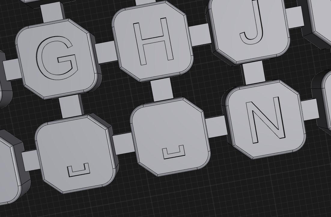
I made the buttons bigger, which meant I needed to remove the taper to maximise the material between them. Getting round this means tying all the buttons together internally, meaning that adding legends was then possible
![]()
The keys could then be a single entity that can be dropped into the case. This would also open up opportunities of having alternative key maps available that could be swapped out reasonably easily. Printing on MJF printers means that even these small buttons come out well
![]()
I didnt go deep enough with the legends, so you can still see them from some angles, but generally they are a bit useless. The bigger problem of course is that the very rigid print with some snug fitting meant that it was super hard for a single button to move independently.
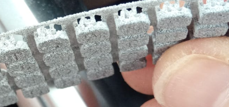
MJF printing has a bit of flexibility with the limits of what you can do. I had a bit of a play with making the buttons springy, while still being tied together. After some messing with CAD I came up with this
![]()
You would have no chance of printing this on FDM, and a resin print would be able to do the detail, but support material needed would make it too hard to process afterwards. This limits it to MJF or SLS printing, so that the un-fused powder can support the part.
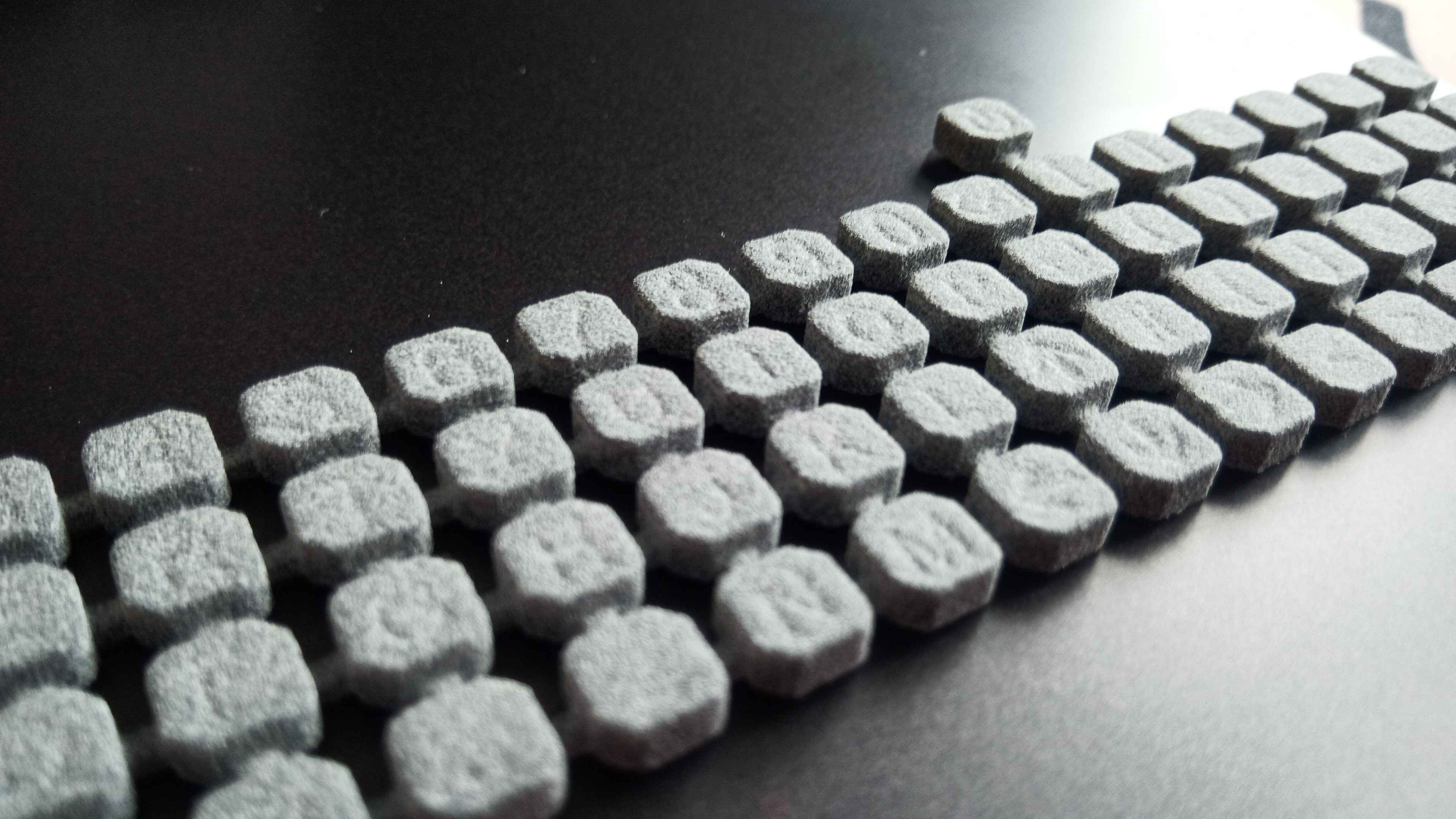
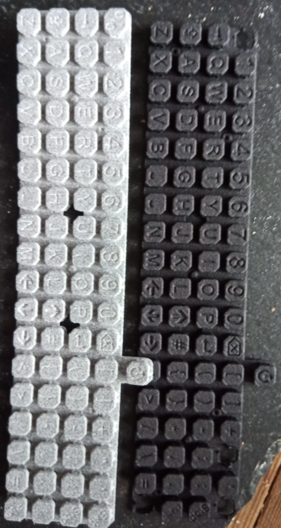
Thanks to the guys at Midlands3d for trying to print this monster!! I originally chose the dyed black option, which gets shot blasted before it is dyed. it seems the shot blasting was a little too much for this design, and some of the keys vanished without a trace. They re-printed it in bare grey material and it came out pretty well
![]()
Its quite hard to photograph as its all pretty tiny, but the clearance round the springy bits wasnt enough, so its all fused together and become a solid lump again. The legends are there though this time, and the blasted and dyed version looks way crisper (ignoring the missing keys :P )
![]()
(please excuse the fuzzy photos)
So back to the drawing board we go, onwards to the holy grail of a nice tiny keyboard... and making it strong enough to dye black, because that is sexy!!
![]()
How good really is MFJ printing?
I knew MFJ printing was good, but I got a surprise on this print!! I have step files for the screws im using to hold it all together so that I can see how far they will penetrate the case and check for clearance etc. when I exported the STL for the keyboard, I had left the screws active in the CAD, and so they were printed too!!
The screws are 1.4mm diameter, so you wouldnt expect them to print, but they were sat popping out bold as brass (and out of focus!!)
![]()
i popped them out and compared to the real screw, its really impressive!!
![]()
-
Power to the people
09/06/2024 at 10:36 • 0 commentsSo a mobile device needs power, and to make a mobile device more useful, more power is always better right?
Initially I had considered just popping a JST socket on the board and calling it a day. That would make the case design much simpler, and could even save 2mm on the thickness of the device, making it even easier to slip in a pocket. Job done right??
Well if I ever want to sell these (and I would like to!! ) then an enclosed battery becomes a major issue! Anyone following along for a while might have seen my past fun with Royal Mail and batteries . Being able to ship the device without a battery makes life much easier, but it needs to be a battery that the end user can easily get locally, for a reasonable price.
18650
Any local high street these days will have a choice of vape shops, and those shops will generally be a source of the ever useful 18650 lithium battery. They have become the AA battery of the modern world. The biggest issue with these batteries is there cylindrical nature. The battery being 18mm in diameter makes any device you use them in harder to make thin. Take that 18mm, add 2mm each side for the case, and 1.6mm for a pcb, and your up to a chunky inch without trying. Pockets are not too happy about that....
That Nokia battery that everyone uses
If you buy an electronic device that has a removable battery, the chances are it will be rocking a "BL-5C". This means it will super easy for people all over the world to get their hands on the battery. The use of these types of cells also has added advantages. They have hardware based reverse polarity protection (as long as you design the battery bay right, you cant connect the battery the wrong way) and they are supposed to have protection circuitry built in too (although i wouldnt want to trust that on the cheaper cells). The battery is only 5mm thick too, so even with some case and pcb, its still going to be thinner than a 18650 cell on its own!! All is not perfect though, when you look at the battery, its contacts are little gold squares on the battery, you need to find the right kind of connector to mate with this efficiently. a quick search and you can find hundreds of people selling you a 'nokia battery connector' which will do the job
![]()
The problem comes back to 'if I want to sell these'. its easy to find random connectors in small quantities, but if your thinking of getting a fab house to make your boards, you need part numbers and someone who can reliable offer larger quantities of the part. This is where I fell short
The Other (one of many) Nokia Batteries
While i was hunting for battery connectors, a friend mentioned a Light he had acquired from AliExpress, and it too had a removable battery, but not the magical standard cell. This one was a BP-4L from the more modern range of Nokia phones (E61, E63, etc) and the first advantage I came across was a reduction of thickness!! 4mm rather then 5mm (a win for pocketability!!) the next bonus was a 50% increase in capacity! 1500mah rather than 1000mah. Then the final decider was that i could find a battery connector!! This cell has a spring based socket connector on the battery, and 3 simple blades attached to the pcb
![]()
We Have A Winner...
So here we are, BP-4L is the way to go!! Still got hardware based reverse protection, slim to make it easy on the pockets, and a session busting 1500mah battery!! That means that even if you have an average 100mah running load, and you average an hour a day usage, that battery could be lasting over 2 weeks!! I call that a win :)
-
Just because it looks the same, doesnt mean it is!!
08/27/2024 at 14:05 • 0 commentsSo if your looking for a screen, you will find many different stores selling many different options. When I was looking for screens for my TinyPi project, it didnt seem to matter where the screen came from, they all worked the same.
E-ink seems to be a very different animal all together! each screen seems to have different properties, and even when the datasheet says it is the same driver IC, they are configured in different ways.
Before we go any further, let me just take a moment to shout out to the 'screen whisperer' Larry Bank. He has worked with me, tweaking his screen library to get the most out of these screens, without his work, I would still be struggling with bits of demo code
Screen 1
The first screen I ordered looked lush!! the background was frosty white and the contrast was brilliant. With a bit of tweaking the refresh rate was ok, but needed to be faster.
Screen 2
Enter screen 2, used a supplier that I had used in the past, the screen was much greyer, and it didnt look anywhere near as nice. The fast refresh was not working out of the box, but I didnt see the point of trying to fix it, as the screen didnt look as nice.
Screen 3
Talking to a friend and they told me about another supplier. They have their screens listed as 'fast update' which was music to my ears. After an impromptu 9 day holiday at the airport, the screens landed. The difference was quite remarkable!!
running the same code on both screens, the new one has a much more savage flash, but its over so much faster than it makes a massive difference. With some demo code that lets just just type random stuff onto the screen, you can see its pretty usable, and you can do many fast updates with no obvious grain appearing on the screen.
the hacking continues....
-
Keys to the kingdom..
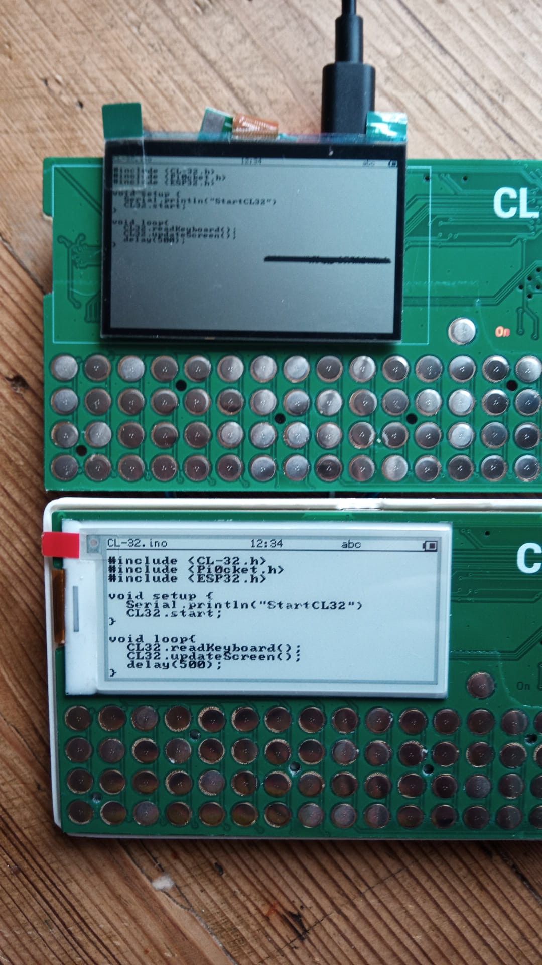
08/22/2024 at 12:05 • 0 commentsIf your making a keyboard, your gonna need plenty of keys right? This is an easy enough task, you just need to plop a load of buttons onto the pcb and your done. I didnt want to waste i/o pins reading the status of all those buttons so I have made use of a chip that was made for the job.
The TCA8418 chip can monitor up to 80 buttons, using minimal power and storing the key events in a nice little buffer so that you can process them whenever you are ready.
Using proper keyboard switches would be the ideal for the most usability, but they are not really pocket device friendly. there are smaller tactile switches, but once you start adding many multiples of buttons, the cost starts to shoot up.
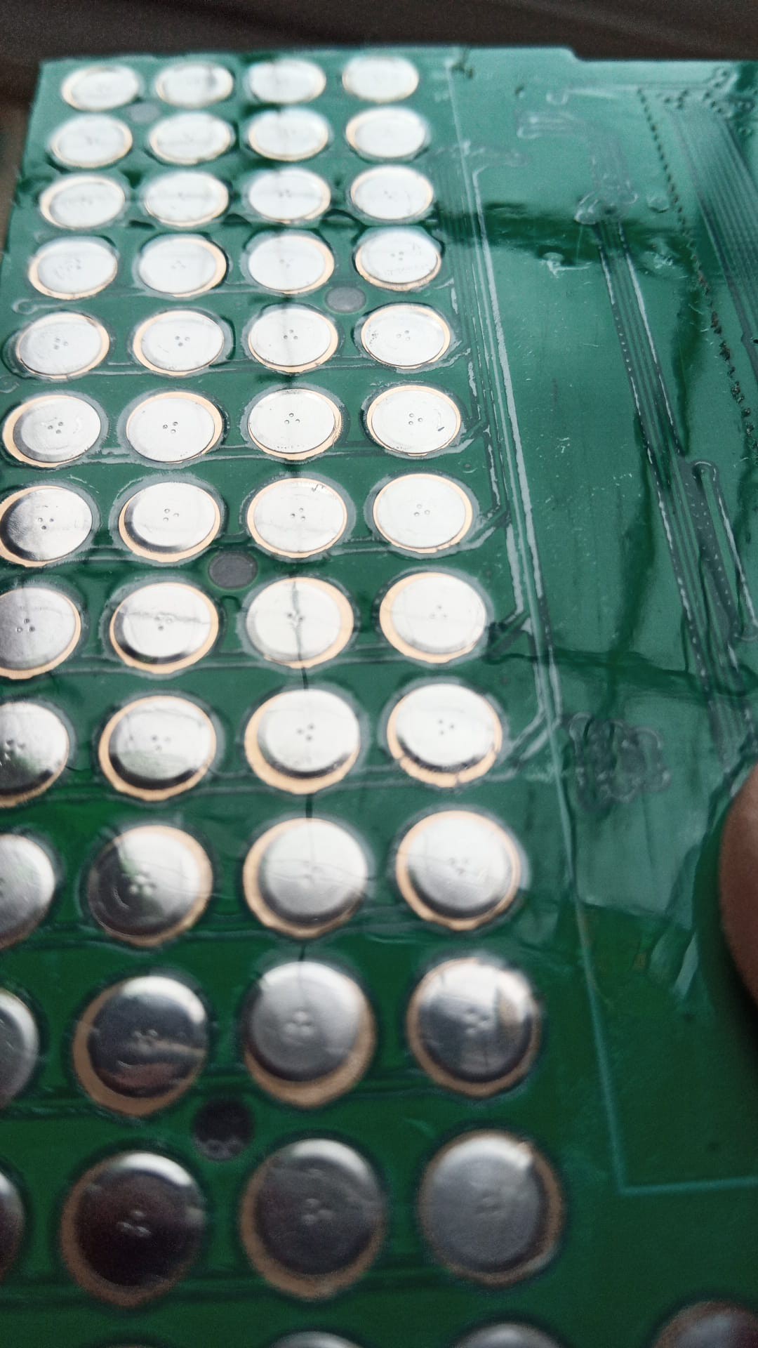
If you have ever taken any small mobile device apart, you might have come across buttons that are stuck to the pcb under a plastic sheet. These are 'snap dome' switches, essentially taking a standard tactile switch and stripping it down to almost nothing. The pcb has 2 contacts on it, and there is a metal dome sat on top. pressing the dome deforms it, making it bridge the 2 contacts. The domes are arranged on an adhesive sheet, so they can be installed easily during manufacture. These custom sheets are actually really cheap, but the minimum order quantity on them is normally in the thousands, so prototypes and changes can get expensive.
It is of course possible to buy a bag of the domes, and make your own sheets with some tape and some steady hands... and the help of a 3d printed guide
![]()
lay some tape over the top, and then peel it off and transfer it to the pcb
![]()
Its not perfect sure, but its close enough to test :)
The other part to the puzzle is the strength of the domes. The ones I have used in the past were pretty 'strong' so when they were pressed and deformed, they had a loud and tactile click (hence the name clicker)
I wanted to get away from the noisy clicking (can you imagine a classroom full of clicky buttons being pressed) so I went for the lowest strength domes I could find. at a mere 55g activation force, you can almost trigger them by blowing on them!! I think there is some more experimentation needed to find the sweet spot of tactile feeling and minimal noise.
The quest continues....
-
E-ink Really??
08/21/2024 at 15:22 • 4 commentsI wanted to stick to the retro asthetic, so the screen being up the top left corner feels right. I considered a few options, but kept circling back round to e-ink.
Colour LCD
There are lots of really great little IPS screens with really impressive pixel densities, but they are generally designed for smart watches and the like, so they are super tiny (see TinyPi Pro ;) )
Monochrome LCD
I did try and hunt for some dot matrix lcd screens to really nail the retro aesthetic, but they seemed to be low resolution and pretty expensive. Also they can be a bit tricky with viewing angles and hard to see in low light
E-ink
So e-ink was the next on the hit list. I really love the way it looks, literally like printed paper, but the refresh rates are shocking. For displays with any colour on them, it can be up to 15 seconds to refresh the screen with lots of flashing, not really something that works well with a keyboard in a code editing situation. After some research, I found that the plain black and white screens could fully refresh much faster, and there was the option of fast or partial update which might make it usable...
The Curveball..
I had in my box of bits a Sharp Memory display, its a low power lcd that has a bit more of a reflective nature to it, and so has a bit more readability when the light isnt great. I hacked one onto my test boards so that i could compare and contrast
![]()
At first, things look nice!! (disregard that blob of damage on the screen) there are more pixels, and the refresh is instant, but it soon started to loose its shine. Firstly the extra pixels means that you have to use larger font to keep the same level of readability. While this is not the end of the world, it does kill off the advantage gained by the higher resolution. Also as i was moving the boards about, i noticed shocking contrast when your not looking directly at the device
![]()
Compared to the crisp e-ink, this was pretty bad. Coupled with the fact that i need 5v to get the screen to work, and the poor old Sharp Memory display went back into the parts bin
-
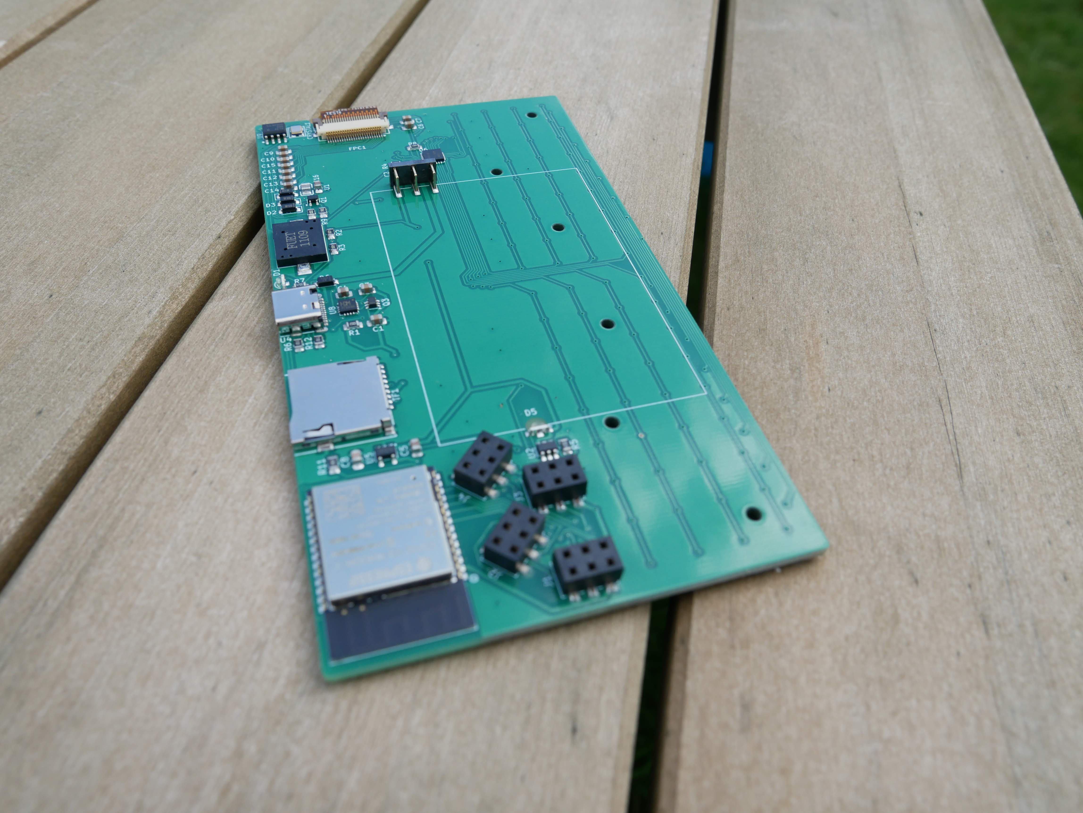
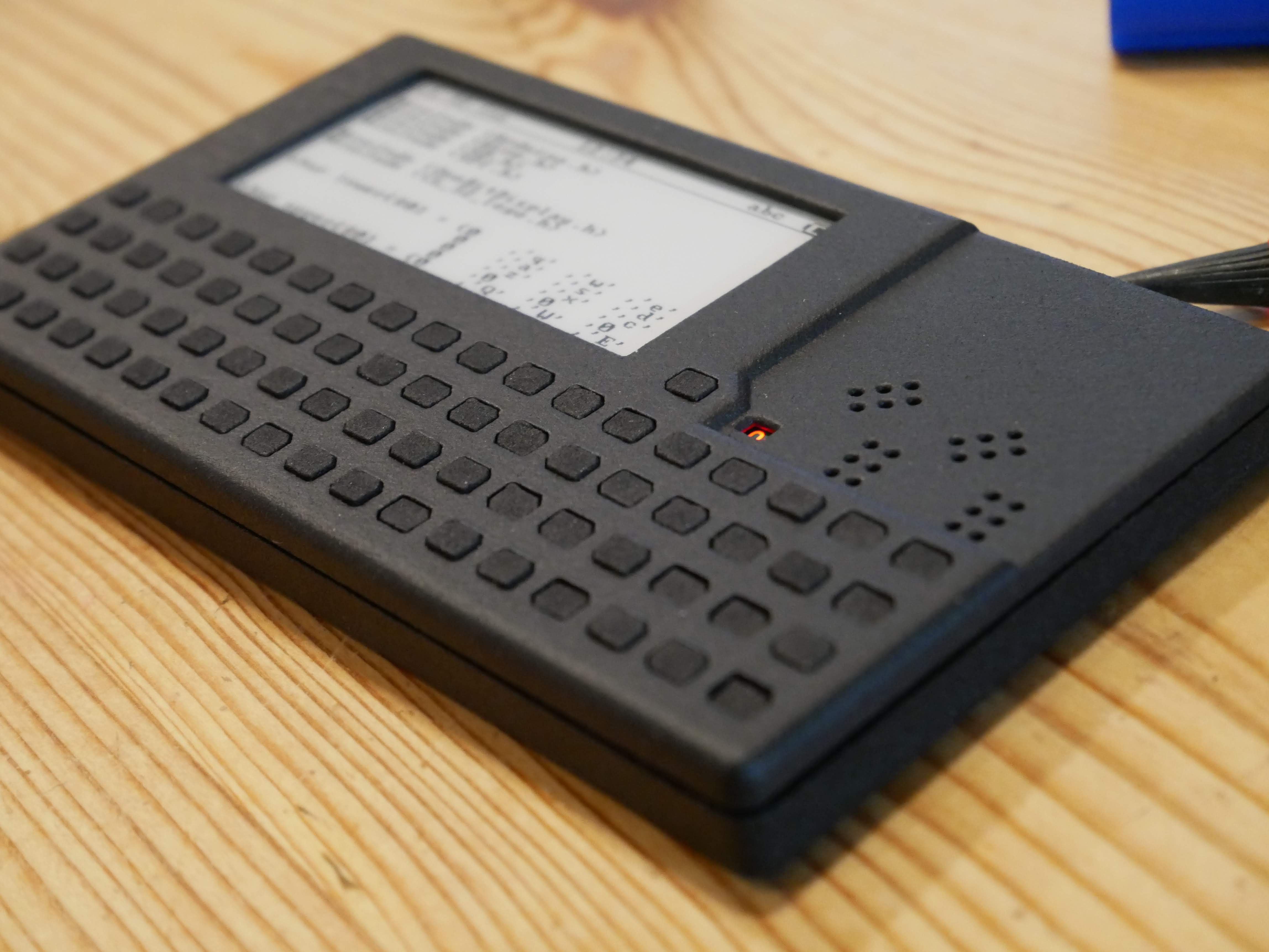
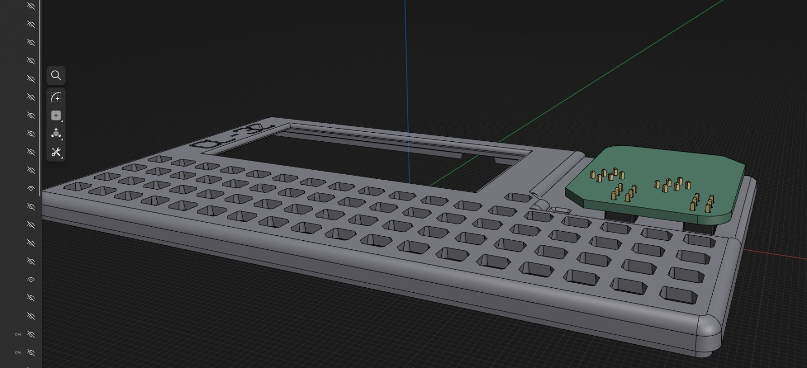
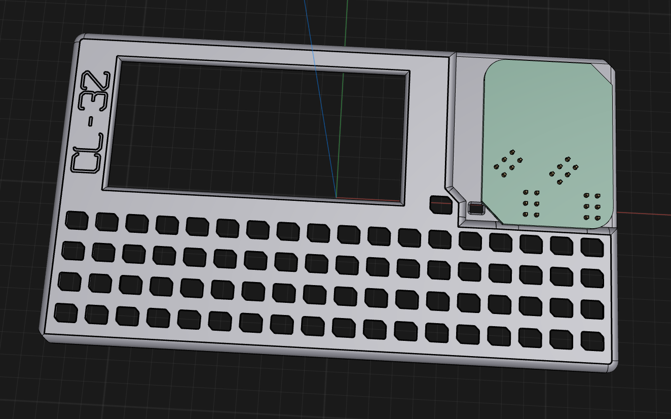
Adding functionality
08/20/2024 at 12:34 • 0 commentsTo make a project like this useful, you either need to spend a fortune adding all the sensors and 'radios' that someone might want/need, or give the mechanism to add them as needed.
Most systems use Qwiic or STEMMA connections to add additional sensors, but that really limits you to 2 pins, so it is relatively limited unless you use multiple plugs together (if you wanted something like SPI for example). This then opens up issues with getting plugs the wrong way round and things not working as planned.
I was hoping to push this towards the education sector, so using the Raspberry Pi style exposed header is open to damage by a bored student.
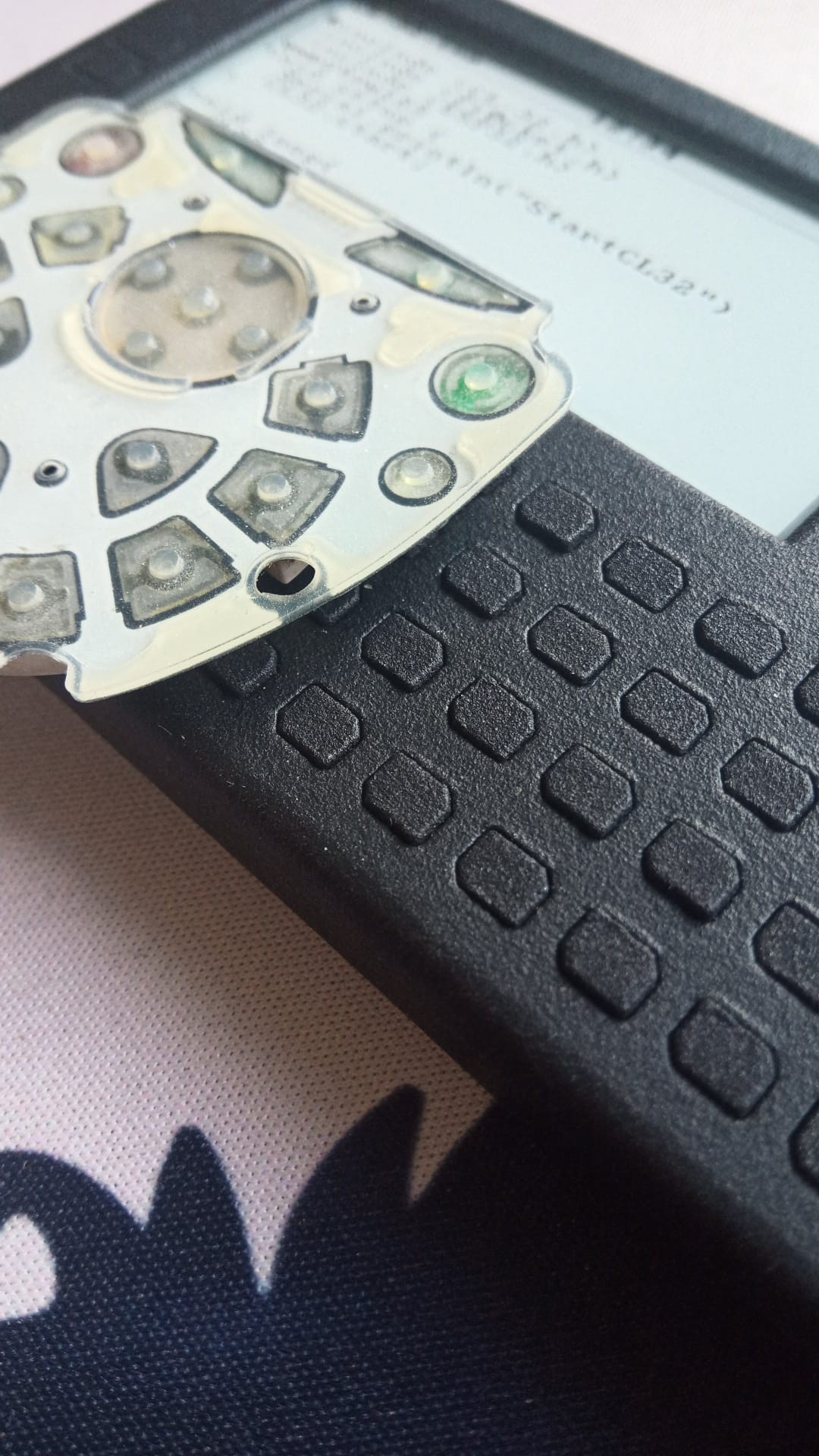
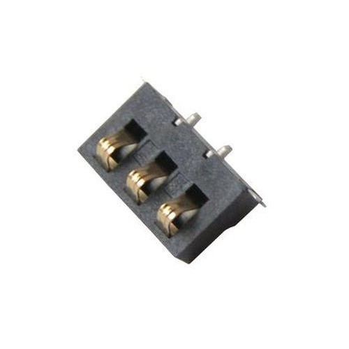
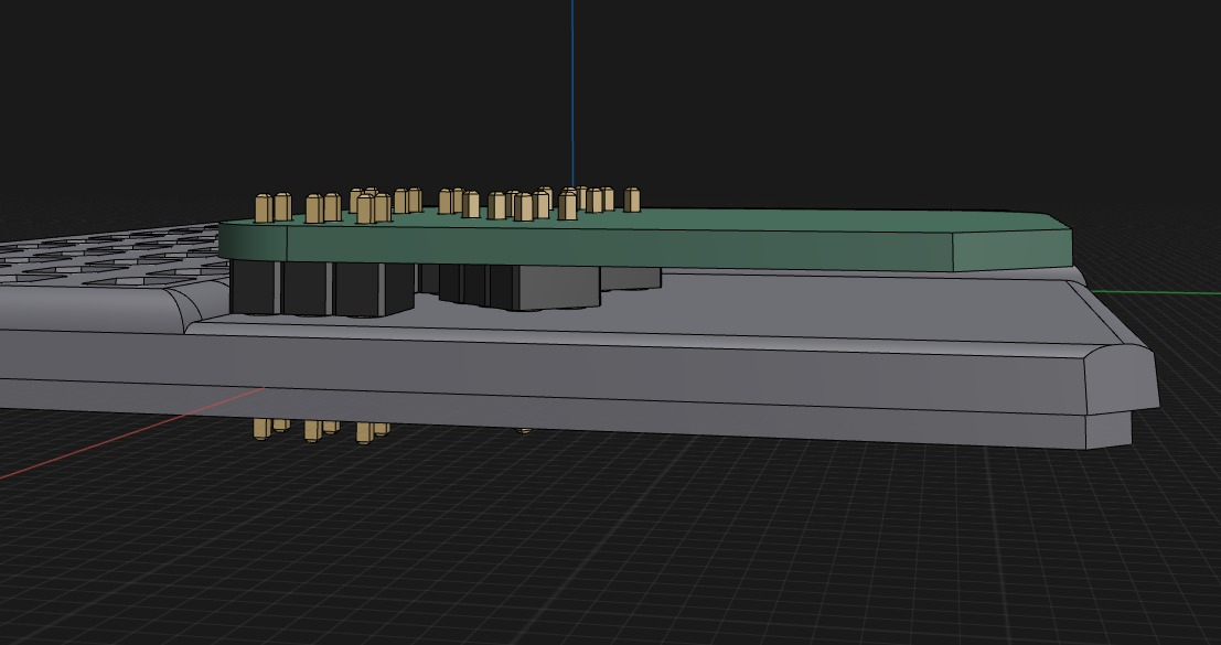
I therefore decided to switch it round, so that the more fragile header pins are on the cheap add on board, and the more robust socket is on the more expensive device. To make assembly simpler (cheaper) the header boards are mounted on the back of the board, using specially designed 'Bottom Entry' headers
![]()
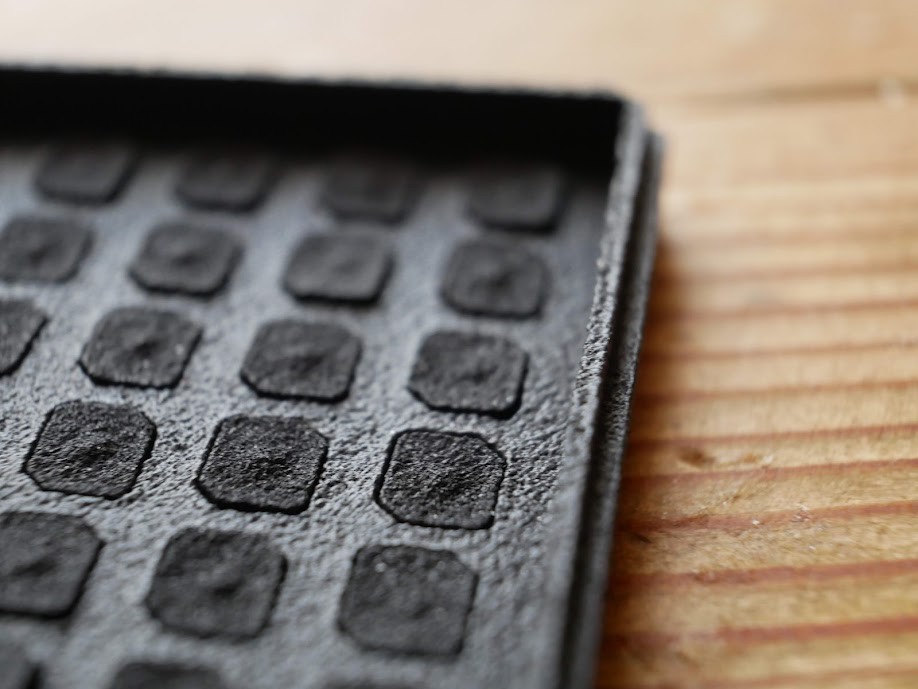
The pattern of the sockets helps to make sure the add on board cant be inserted the wrong way, and limits any possible confusion. The case has a recessed corner with just a few holes as the only clue that there is something there
![]()
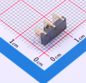
The add on boards only need simple headers to enable connection, giving access to power and ground, and 16 i/o pins
![]()
![]()
using thru hole headers means its more robust, but also could result in the weak point still being the more expensive device rather than the cheaper add on board
![]()