 Andy Geppert
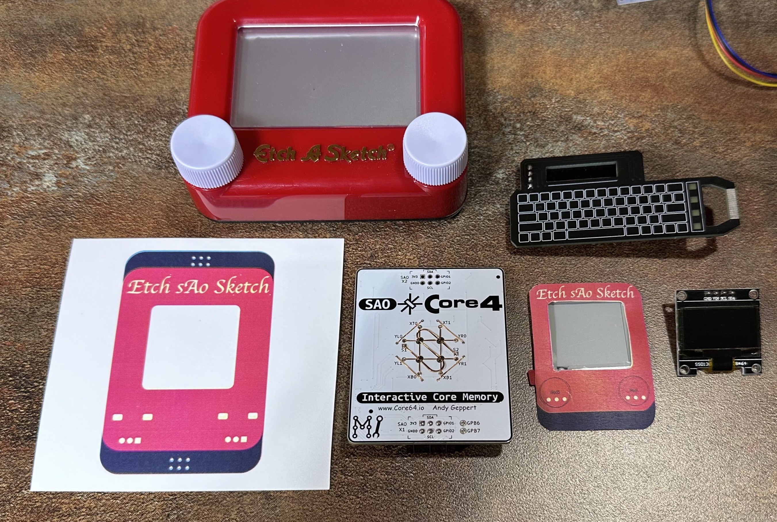
The two big constraints for this design are the size and the desire to keep everything on the I2C bus for the sake of easy access with an SAO port. I think I've pulled together a design that offers the right mix of capabilities and holding up the design expectations with something called Etch sAo Sketch. Here is the V1 design, as released for prototyping.
Also the trick used by [Aaron] in the Macintosh SAO, where the OLED header pins are solder to surface mount pads on the bottom of the board. I also wanted to deploy another trick, using "tooling balls" which I'll share more on later, to align and secure the OLED board to the bottom of my board.
After a several rounds of designing, compromising, component selection, making paper and 3D-printed templates...
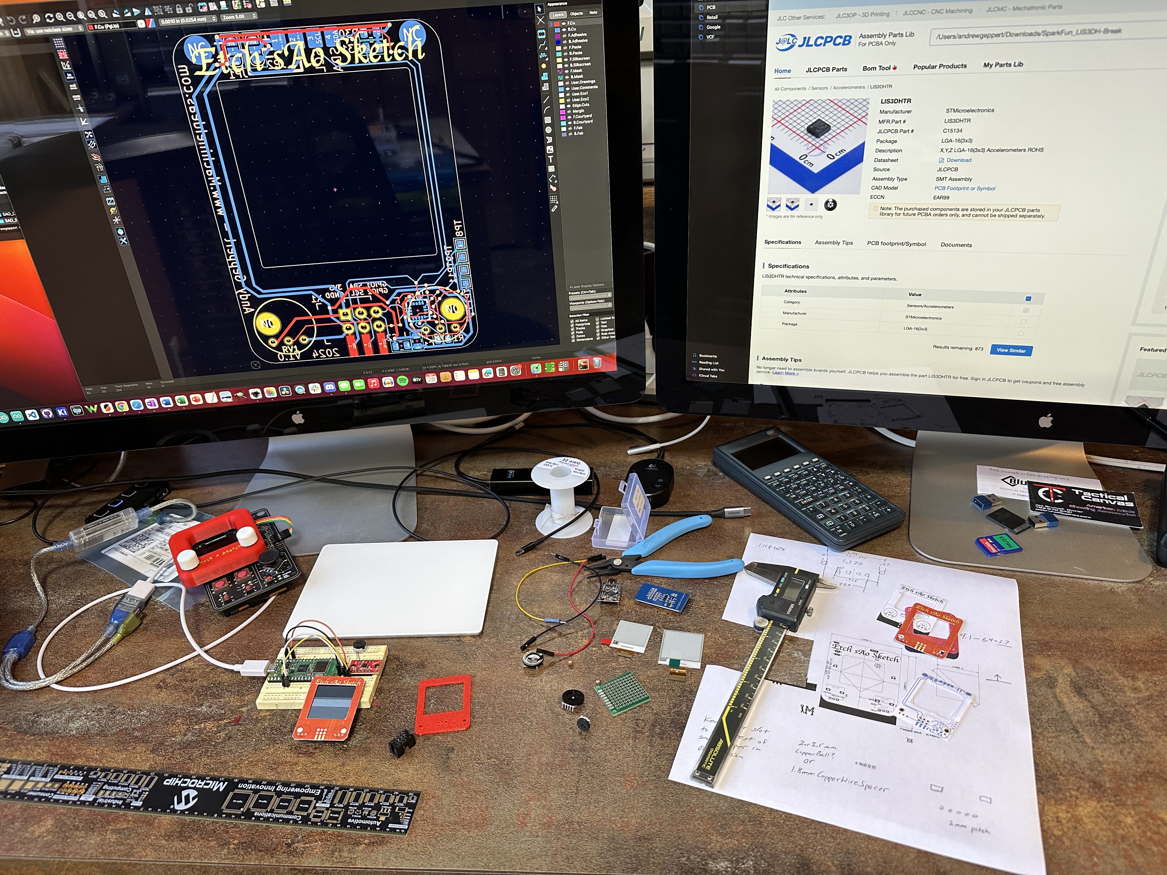
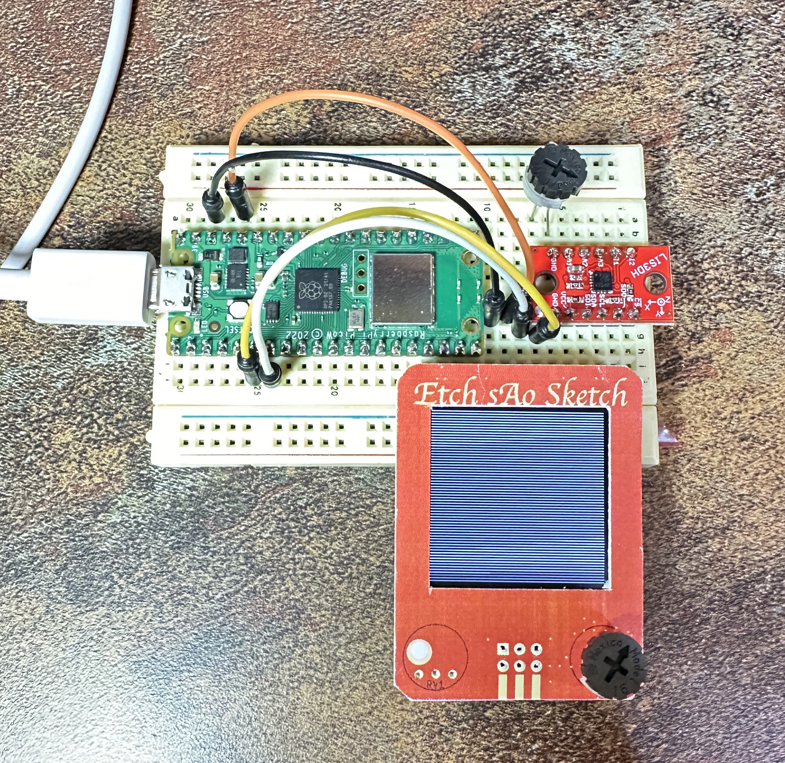
I finally settled on a 1.5" OLED screen and potentiometers that just barely fit, and a LIS3DH accelerometer (with analog inputs for the pots!). This means all aspects of the SAO can be controlled with the I2C bus. Here is a proof of concept:
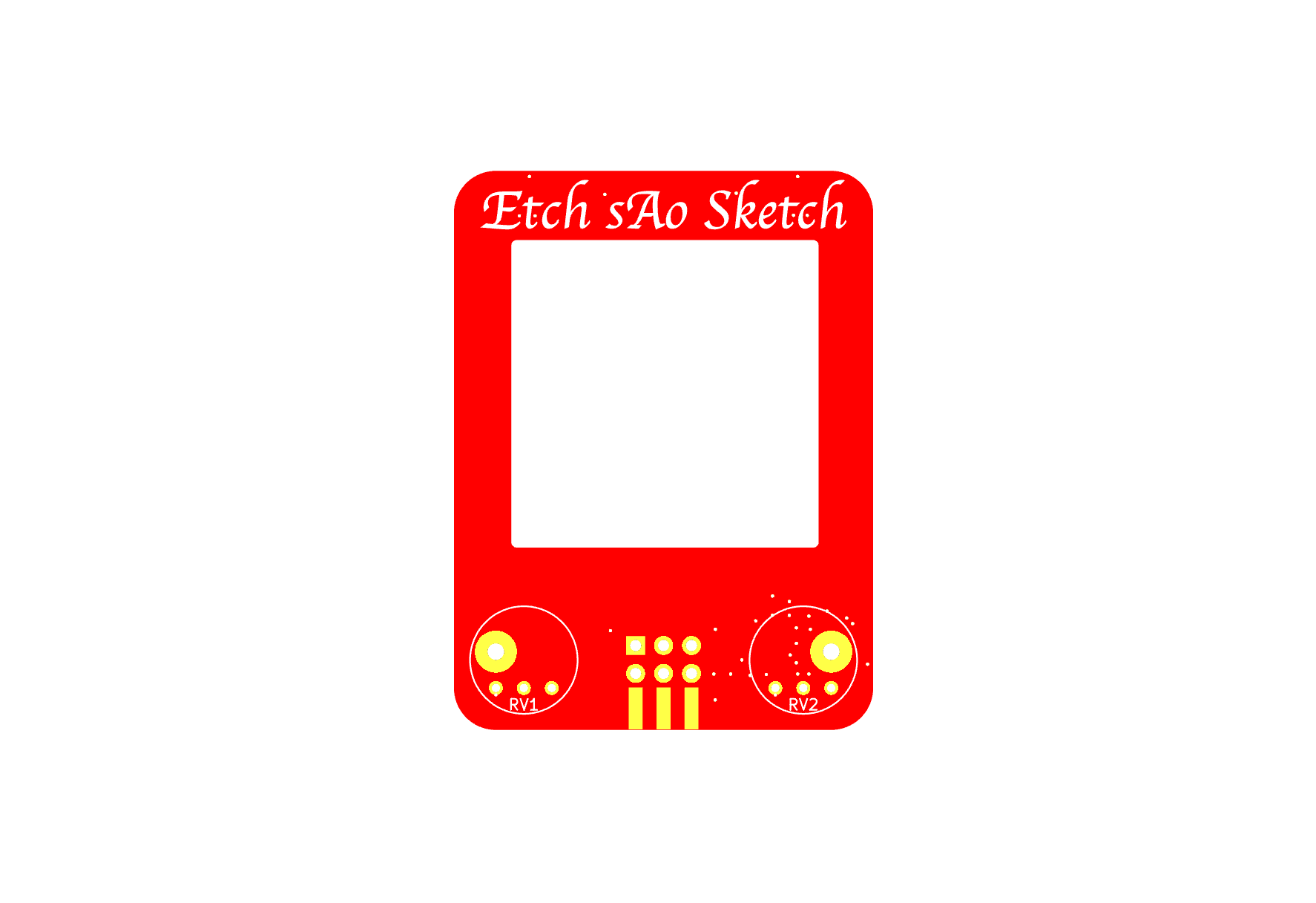
Bonus: these are gray scale capable OLED screens which I'm looking forward to making use of. Here are renders of the board design:
Back side with the accelerometer and associated components tucked into a gap between the OLED board, the main board here, the potentiometer, and the SAO socket:
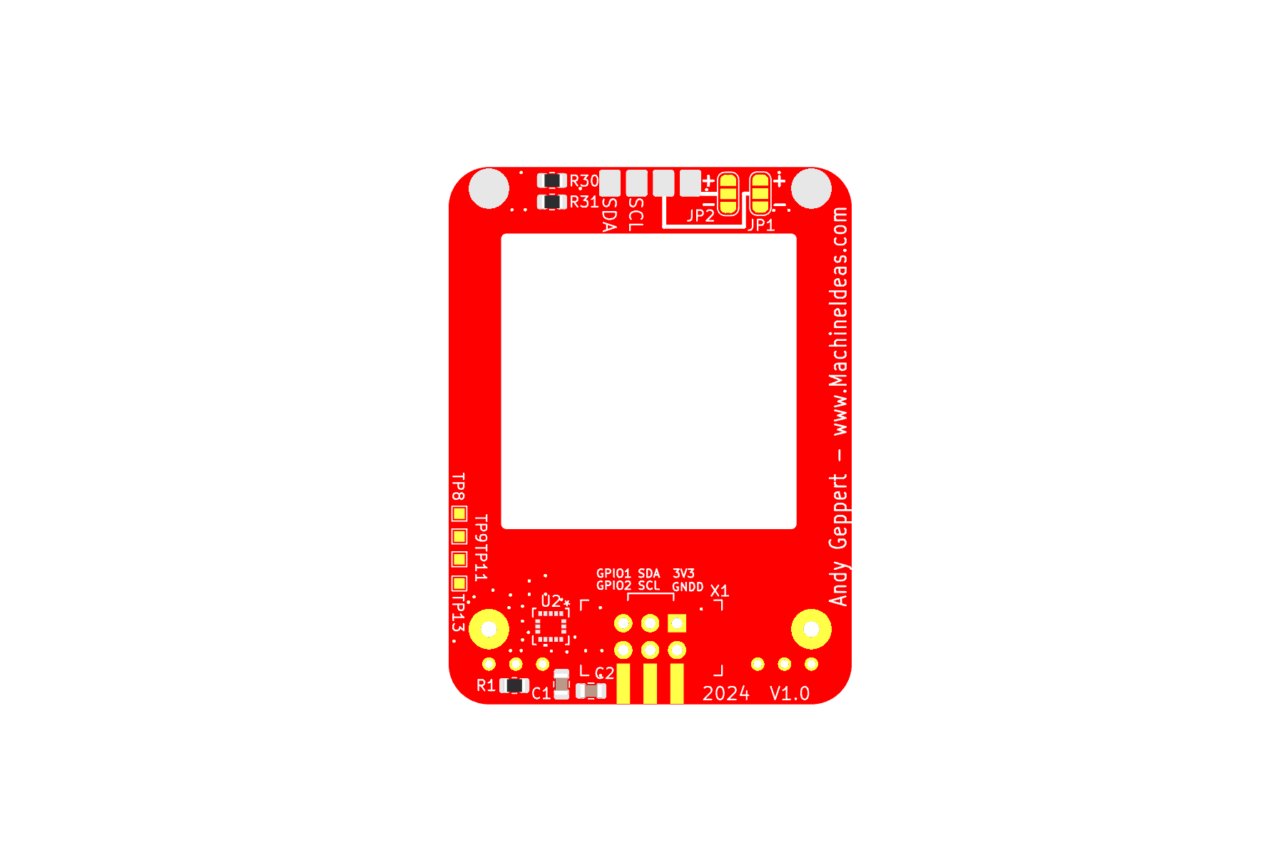
Those big yellow plated-through-holes at the bottom will be used for the tooling ball concept.
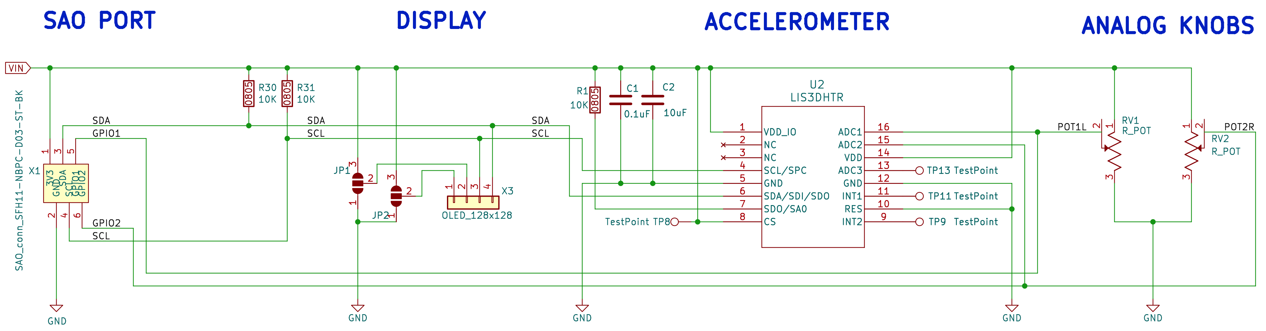
The schematic is relatively simple. SAO Port -> Display -> Accelerometer -> Two Analog Pots. The potentiometer outputs are tied to the GPIO 1 and 2 pins of the SAO port, and into the analog inputs of the accelerometer.
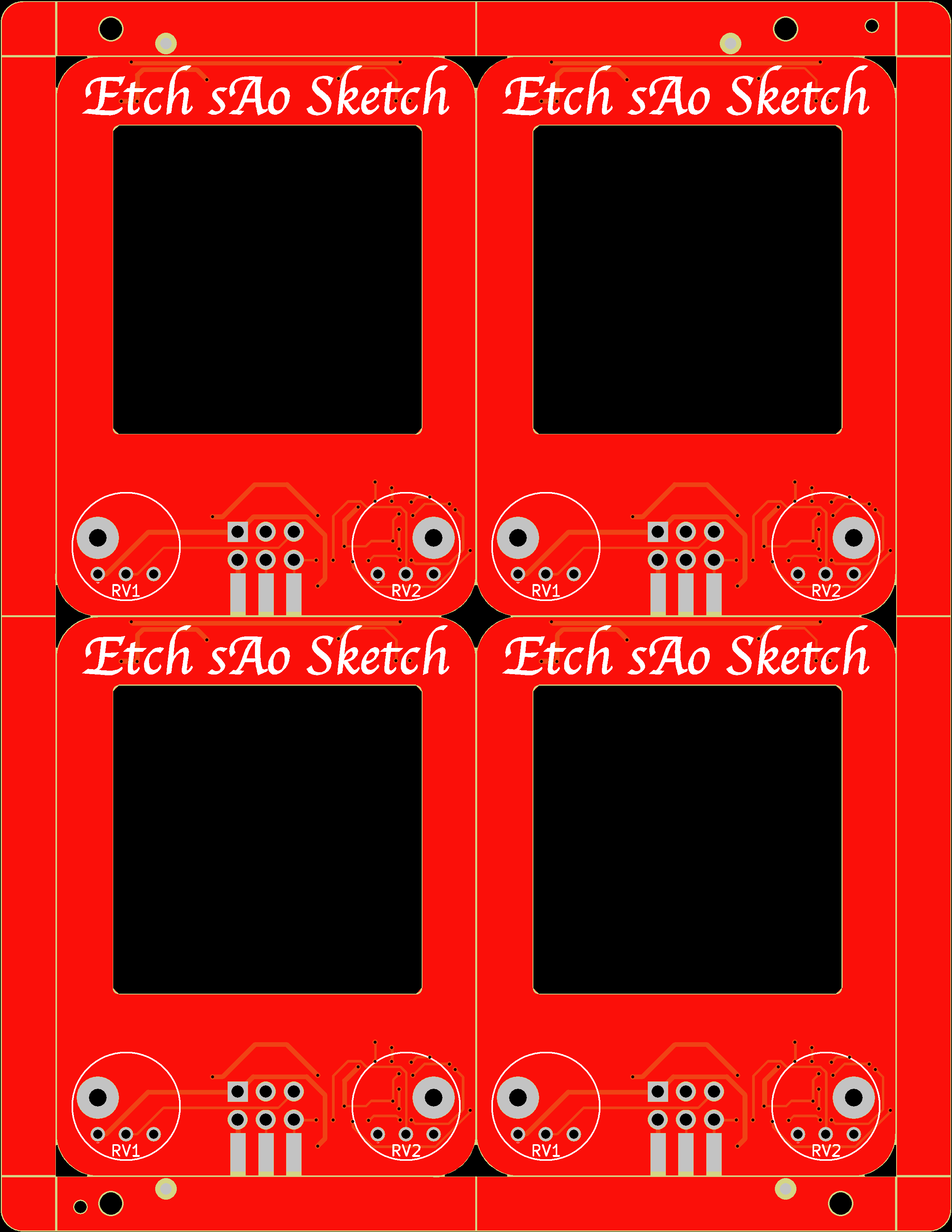
And now it's time to release it for the first round of prototypes. I'm committing to a small batch with the SMD assembly included, and will use the panelization services of JLCPCB to keep the final parts free of fiducials and tooling holes.
I've set aside the ePaper version for now to focus on the OLED version. But the ePaper screen I choose should fit, and with some hacking, I think I can make a proof-of-concept for that version after I get this version going.
Next post should be with parts in hand, and ready to bring-up!
Discussions
Become a Hackaday.io Member
Create an account to leave a comment. Already have an account? Log In.