 Andy Geppert
Oh yeah, these look good!
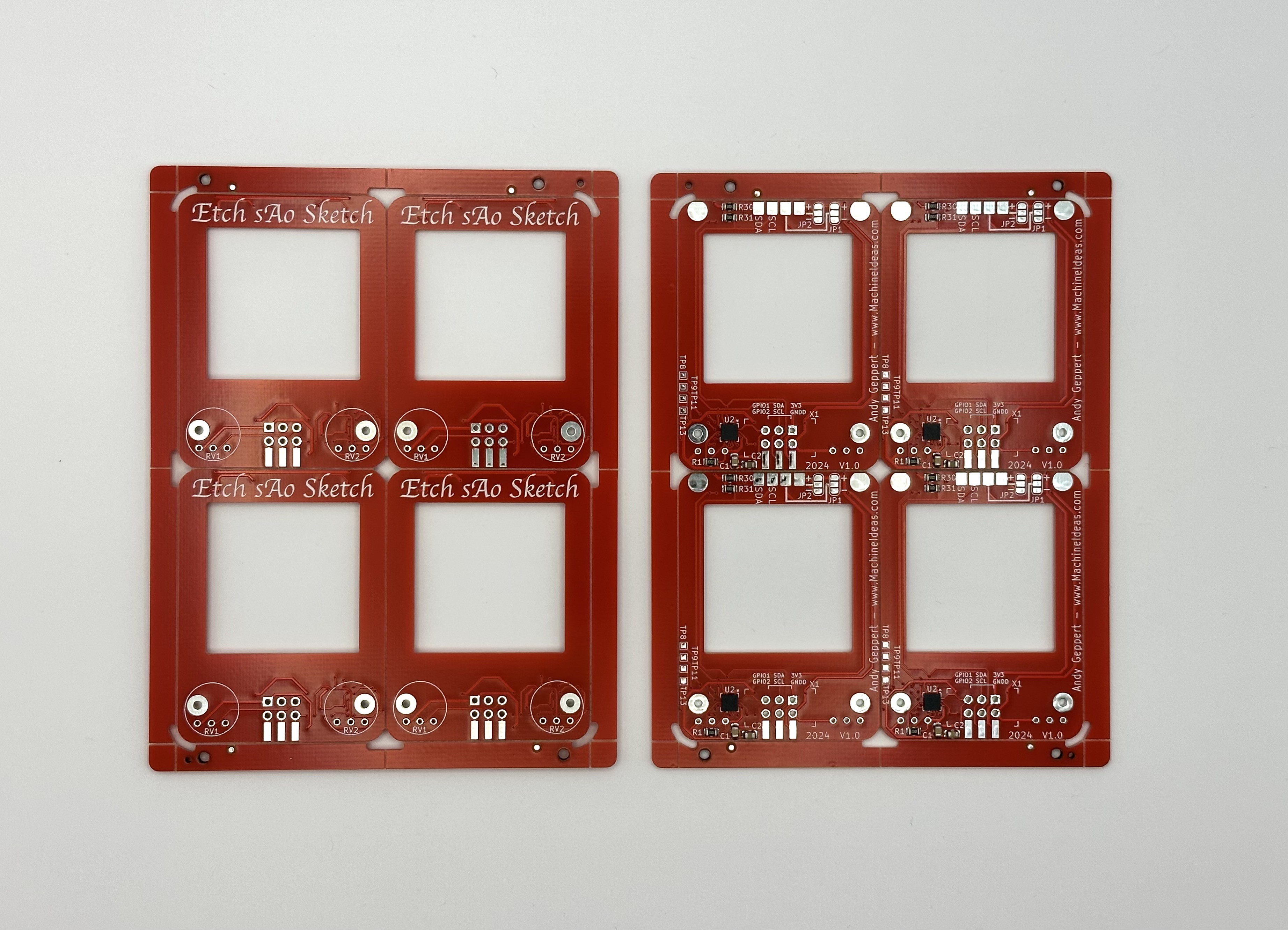
Here are the copper alignment balls in position:
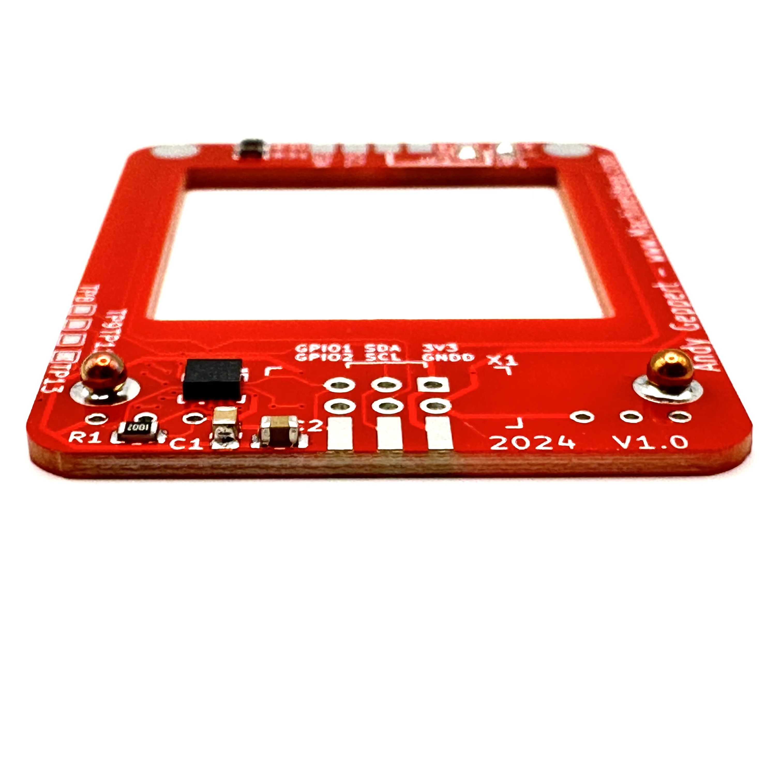
With a gentle pressure between the two boards, the spheres nestle into the holes in the boards and provide alignment between them. They are soldering in place and secure the bottom edge of the boards together:
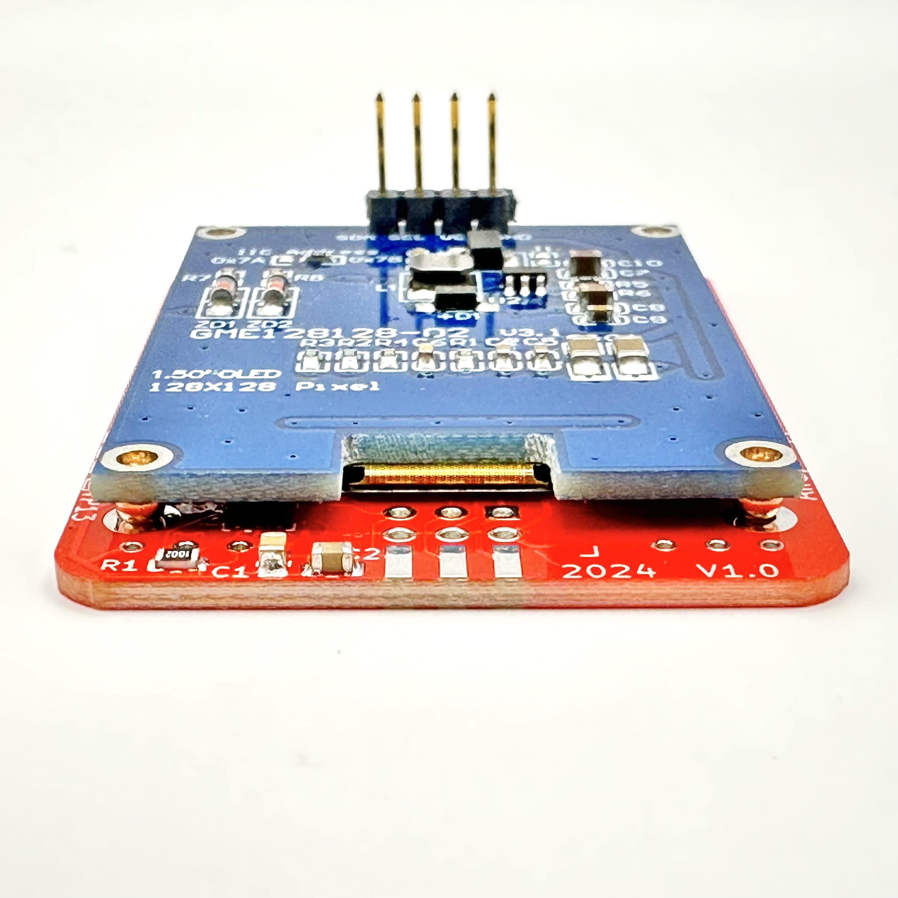
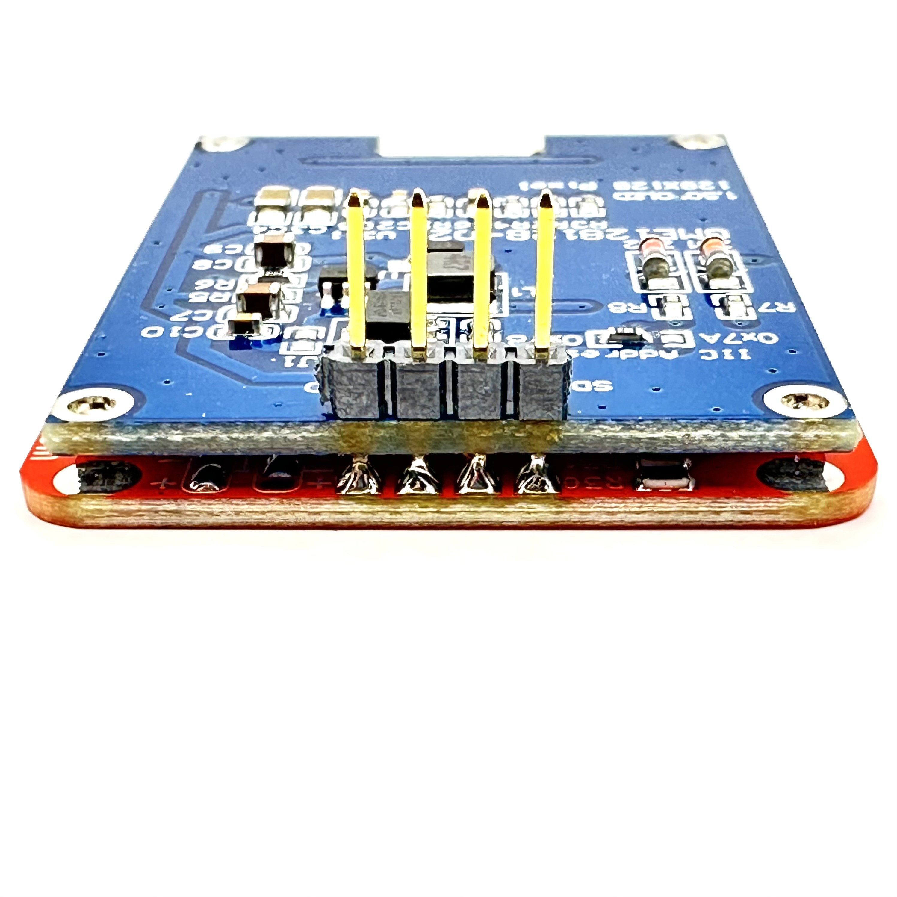
And final soldered of the OLED header pins on the top edge, to connect and secure the other end:
And now for some potentiometers:
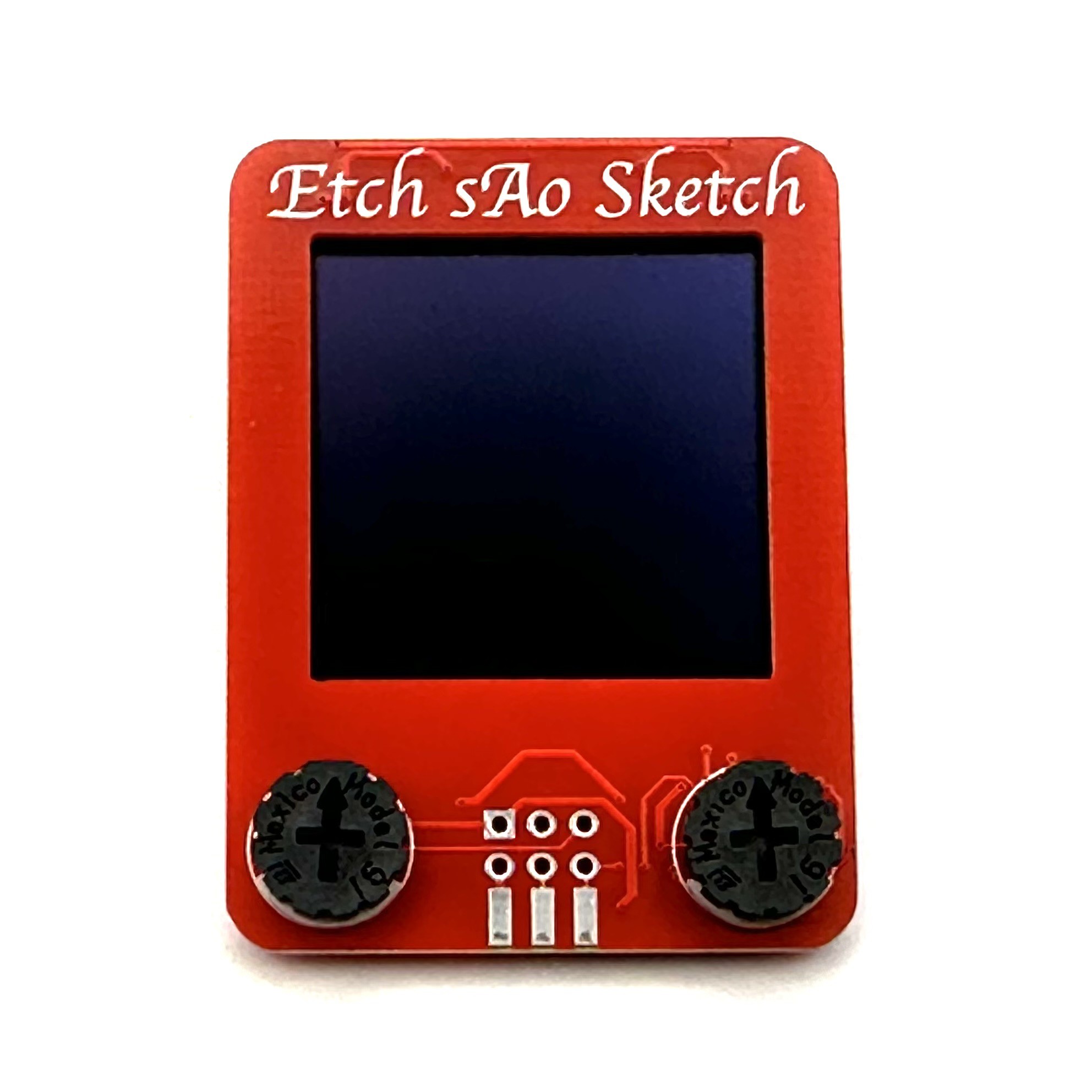
Then apply the proper knobs:
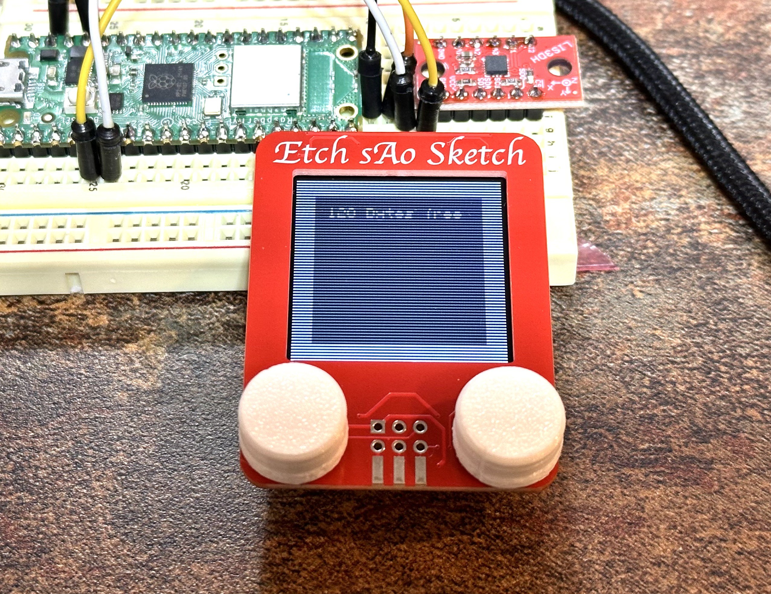
Now it's time for some coding and testing. I ran example code for the OLED and Accelerometer and it worked! In the photo, I'm only connect to the SAO via the four pins that are also anchored to the OLED display.
Next, I need to tie it all together and get the user interface "just right." Including the accelerometers!
Discussions
Become a Hackaday.io Member
Create an account to leave a comment. Already have an account? Log In.
That is a ballsy technique to attach the boards. [Groan]. Looks awesome!
Are you sure? yes | no
:)
Are you sure? yes | no