Background
Last year I had the good fortune of meeting Zbigniew (“Ziggy”) Stachniak, curator of the York University Computer Museum and author of the definitive book on the MCM/70 microcomputer "Inventing the PC - The MCM/70 Story". With Zbigniew's help I built an MCM/70 Reproduction. It was a great experience for me that culminated in my attending the MCM/70 @ 50 event, organized by Zbigniew. The event marked the unveiling of a permanent exhibit in the Steacie Science and Engineering Library at York University featuring a complete line of MCM computers including the MCM/70.
In the spring of 2024 I emailed Zbigniew and asked if he had any other projects that I could perhaps help out with. I applaud his work highlighting Canada's contribution to the microcomputer revolution and if I can assist in any small way I'm in. He suggested CPS-1, the first Canadian microprocessor-based computer. Built by Microsystems International Ltd. (MIL), the CPS-1 supported a 12-bit address bus and a 4-bit data bus.
To learn more about the CPS-1 and the MF7114 please refer to Zbigniew Stachniak 's paper:
Stachniak, Z. The MIL MF7114 Microprocessor. IEEE Annals of the History of Computing, October-December 2010 (vol. 32 no. 4) pp. 48-59.
The Emulator
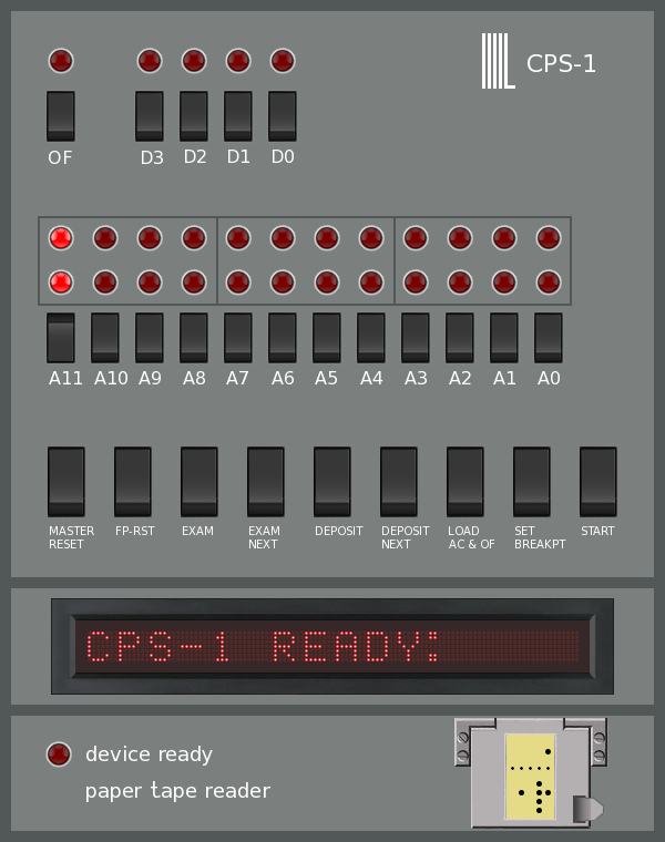
The York University Computer Museum (YUCoM) has already implemented a software based CPS-1 emulator based on documentation they have recovered. The emulation consists of the CPU module interfaced with a front panel, paper tape reader, a plasma display, and a numeric keypad.
Running the Emulator on a Raspberry Pi
Getting the CPS-1 Emulator running on a Raspberry Pi is pretty straight forward. The first step is to get Raspberry Pi OS installed on the Pi. To do this you have to image a microSD card of at least 8G capacity with the OS. There is a Windows program called Raspberry Pi Imager that does this (also available for Ubuntu and macOS).
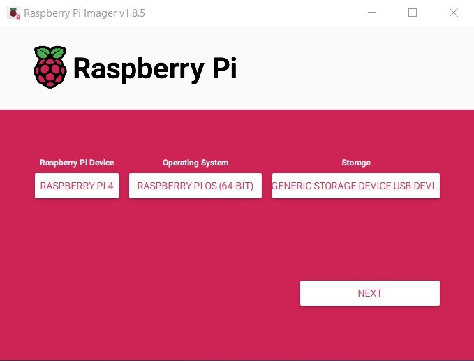
You simply specify the target Raspberry Pi device, the version of the OS you want to install, and the SD card to image. When you press NEXT you will have the option of defining some initial settings on the target Pi. It's a good idea to do this as it simplifies the install.
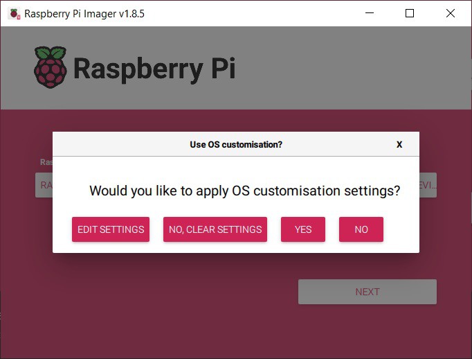
Select EDIT SETTINGS.
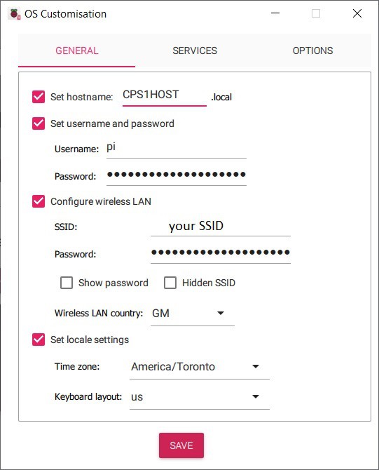
I left the default user name as Pi and the default password of raspberry. Set the wireless LAN and locale as appropriate and press SAVE.
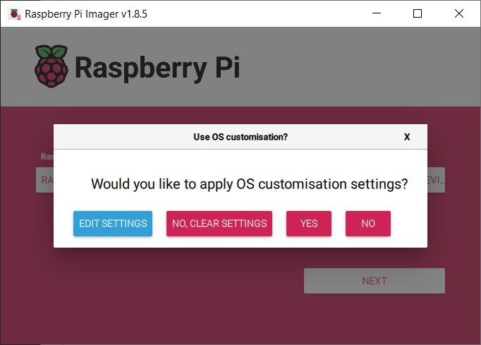
Press YES to apply the custom settings.
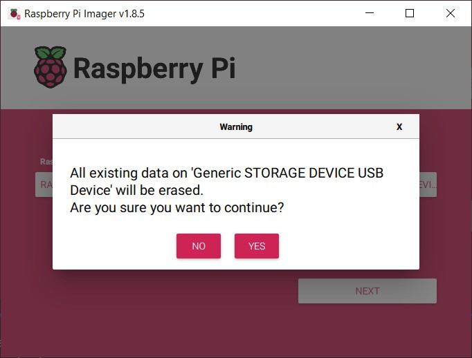
Press YES to continue.
Boot the Pi
Install the microSD card into the Raspberry Pi and apply power. If the imaging has gone well you should see the Raspberry Pi OS desktop.

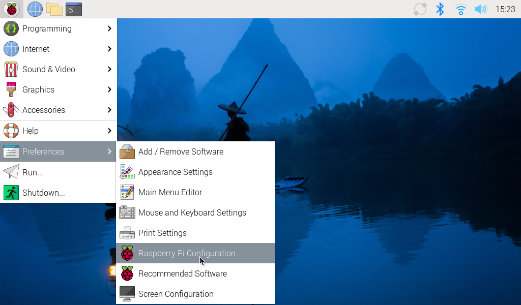
Before you install the emulator there are a few system services that have to be turned on. To do this select Raspberry Pi Configuration in Preferences.
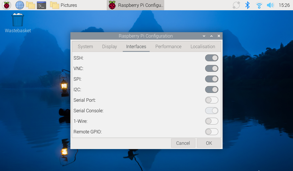
Then enable SSH, VNC, SPI, and I2C and click OK.
The system should be setup to run the emulator now.
Running the CPS-1 Emulator
I'll demonstrate using the The York University Computer Museum (YUCoM) original distribution, but it’s the same for the variants that have the HW front panel integrated. Copy the emulator distribution onto the Pi. You could use SSH or VNC to do this but I just copied the file over on a USB stick. I placed it in a folder I created called CPS1 in the /home/pi tree the exploded the tar file in place.
Next compile the emulator code. Run the following commands.
sudo apt-get install libncurses-dev
gcc cps1.c -lGL -lglut -o cps1
The first command installs a required curses library and is only run once, the second compiles the cps1 application. At this point you should be able to run the application.
sudo ./cps1
Root access is required to access the Pi's IO pins.
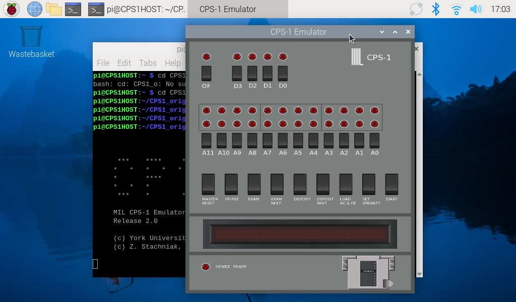
Using VNC
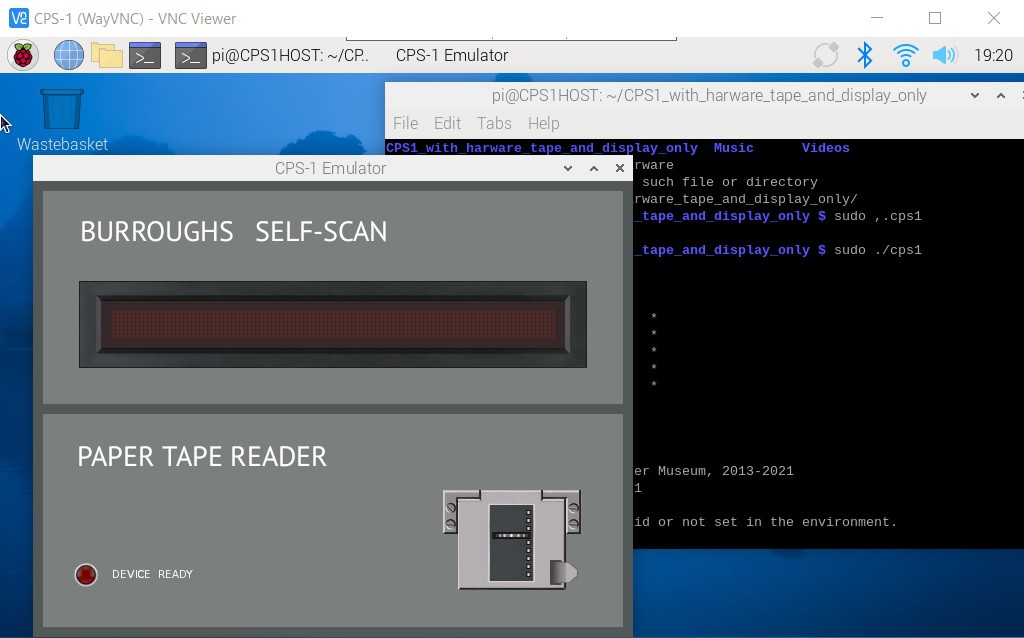
In the previous step I enabled VNC on the Pi. On my Windows machine I downloaded and installed the RealVNC Viewer. This allows me run the CPS-1 emulator "headless" on the Raspberry Pi.
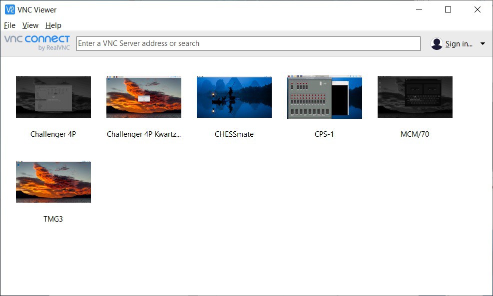
As you can see I do this for all of my Raspberry Pi projects. I setup a viewer for CPS-1 by doing a File -> New Connection then filling out the appropriate Properties.
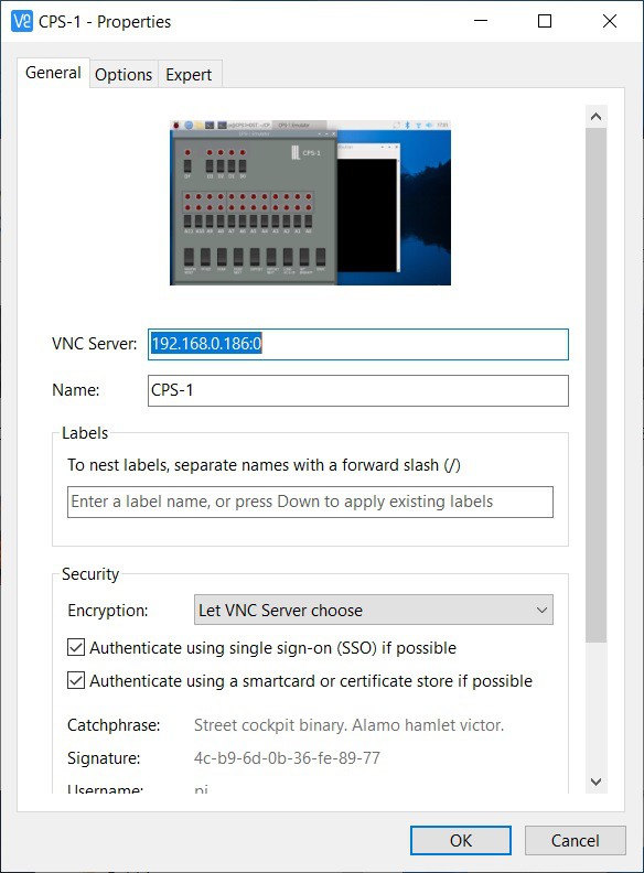
You can easily get the IP address of the CPS-1 box by hovering over the WIFI icon on the upper right of the desktop title bar. To connect to the VNC Server double click the Connection icon.
Autostart
This last step is to make the Raspberry Pi boot directly into the CPS-1 emulator on startup.
I created an autostart folder on my Pi and switched to that folder. Note that pi is the logon user name for the Pi.
mkdir /home/pi/.config/autostart
cd /home/pi/.config/autostart
Into the autostart folder just created I added the following two files.
runCPS1
cd /home/pi/CPS1
sudo ./cps1
CPS1 is the folder when the emulator gets built. For some reason the pigpio library requires root access hence the sudo.
CPS1.desktop
[Desktop Entry]
Type=Application Name=CPS1
Exec=/home/pi/.config/autostart/runCPS1
In addition the runCPS1 file must be made executable with the following command:
sudo chmod 777 runCPS1
If you reboot at this point the CPS-1 emulator should run automatically.
Making a Harware Based Front Panel
As the next phase of Zbigniew's research he had been thinking about implementing a hardware based front panel and asked if I might be interested in tackling this. Hell ya!
Only one problem. No actual CPS-1 computers have survived the intervening 50 plus years. In fact there are not even any photos of a CPS-1 available.
Some Clues
So in the absence of an actual artifact or photo what does one do. Zbigniew started the conversation with a couple of items he had found among the documentation.
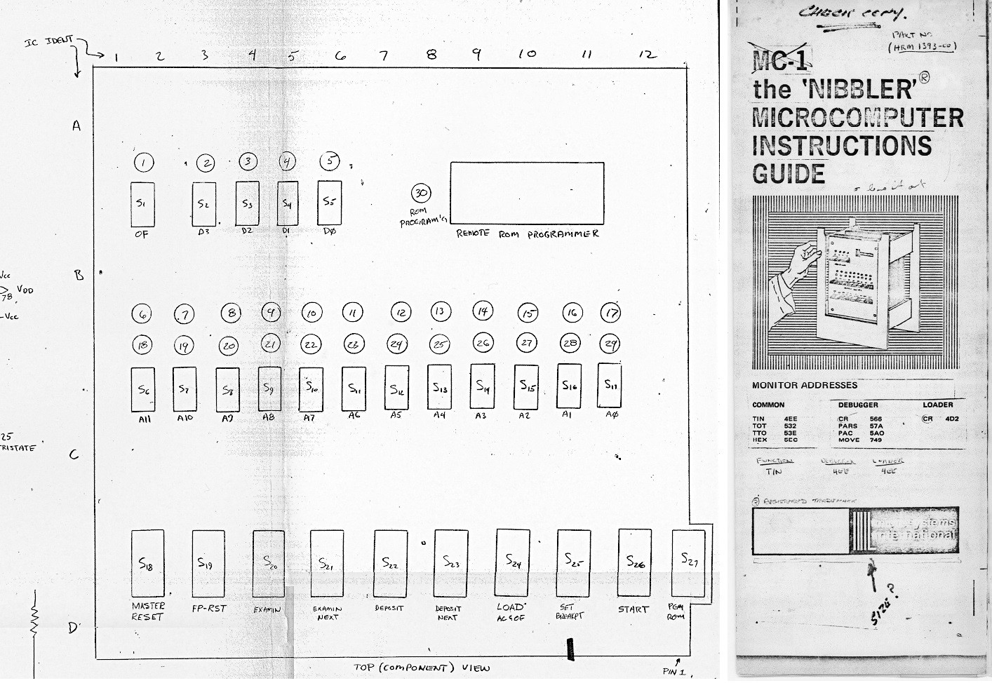
The image on the left is a pretty good clue. It is part of a larger schematic for the CPS-1 that shows the position and functions of the switches and lights on the front panel. This is obviously what was used when creating the UI and controls for the York University Computer Museum (YUCoM) emulator.
On the right is a low detail stylized image of the CPS-1 as it might have been. It is known for instance that the original had a backplane of slots into which the CPU, memory, and peripheral cards were inserted. So check. The layout of the front panel also roughly jives with the schematic image, although this image is so low resolution that I don't think you can rely on the actual number of switches and lights depicted. Switches are shown as toggle style with flat blades that are positioned closely side by side, which is in line with contemporary computers of the day, notably the DEC PDP line of minicomputers.
Based on these images Zbigniew decided that the front panel should maintain the layout of the schematic but look more like the block print image with the switches closer together and based on a toggle style.
Switches
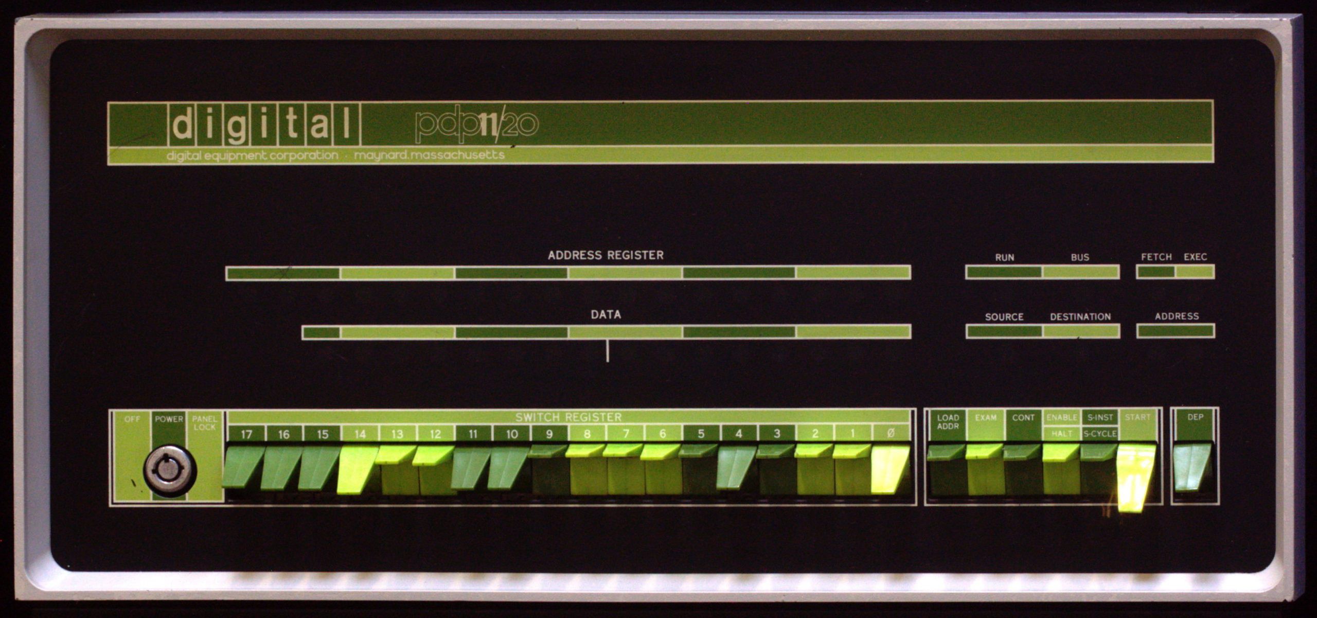
In projects I have done that require switches or buttons I have taken great pains to get both the look and the feel just right. When I asked Zbigniew what kind of switches he would like to see he sent me the following sample images.
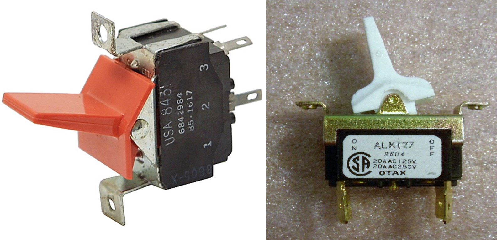
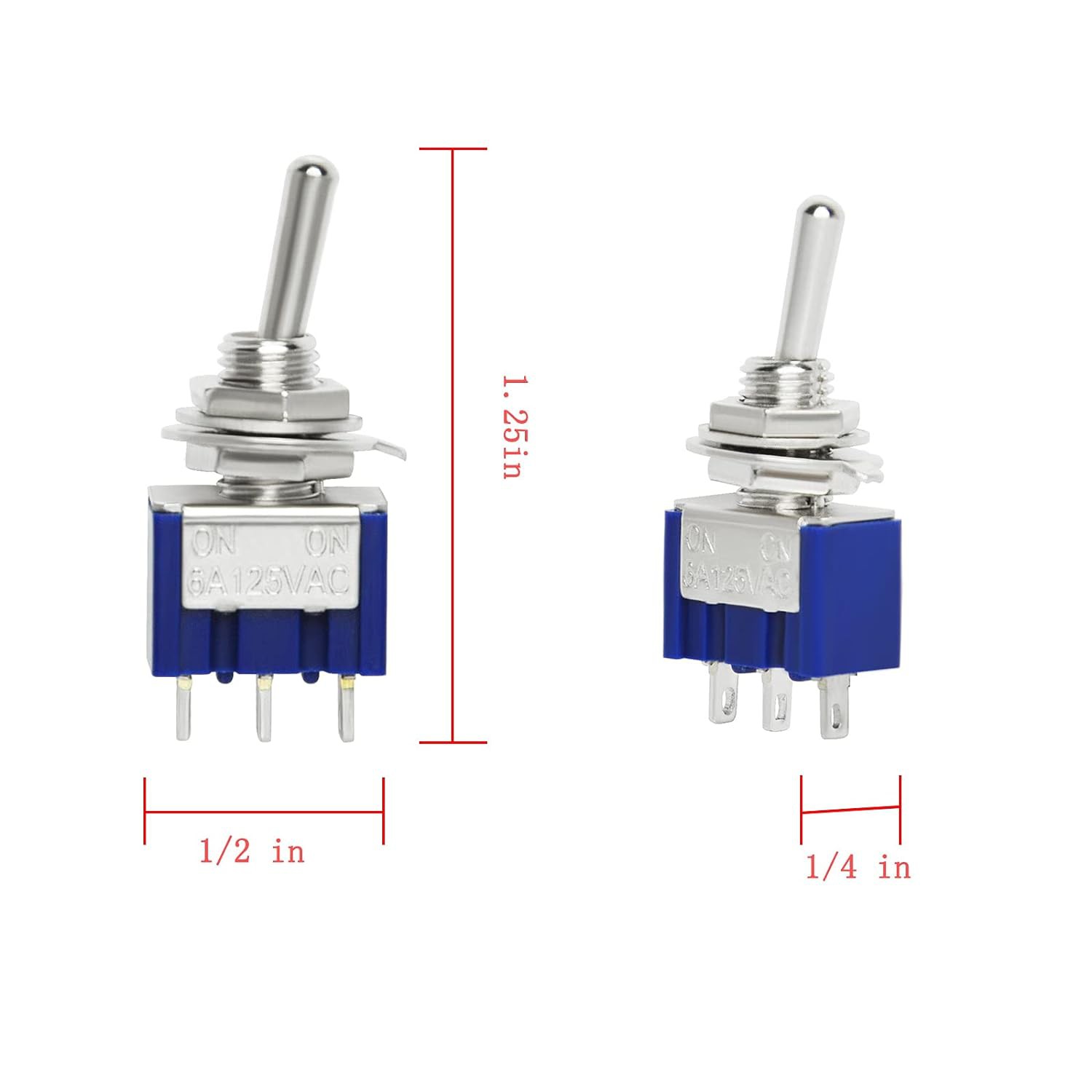
Cool. The problem is that styles change over time and it's often hard to source the perfect switch that has the right look, size, and mechanical characteristics for the job. To that end I have often resorted to "making" my own switches. In this case I though what might work would be to "dress up" a simple miniature panel mount toggle switch.
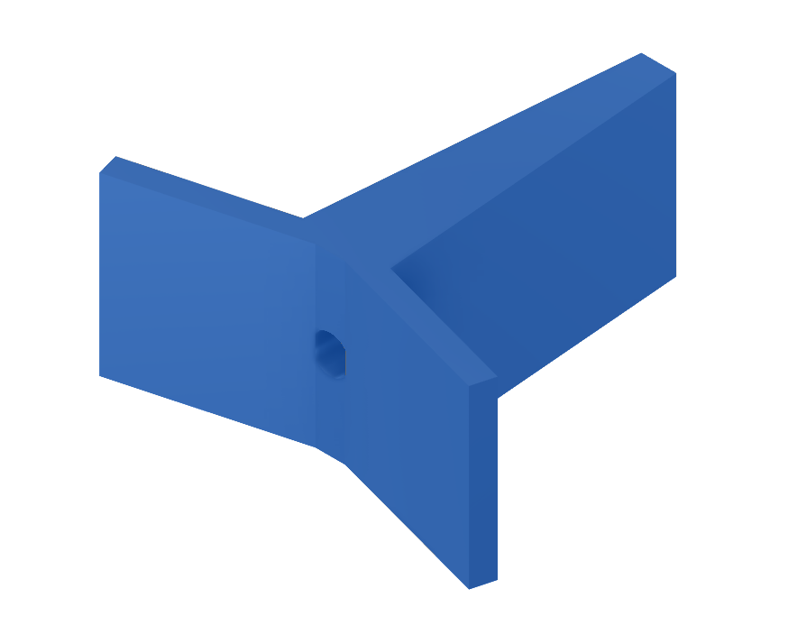
So I started by modelling the switch "cover".
Then I created a little test design to determine how the switches would be mounted to the front panel. The hole in the bottom of the "cover" slides over the toggle lever but then the switch cover needs a "frame" to keep it moving straight up and down.

This setup seems t work pretty well.
Front Panel Construction
So with the switch design pretty much worked out it was time to apply this to a full panel.

On the left is a photo of all of the pieces that go into the panel. The main part is the frame that holds everything together. In addition to mounting the switches and keeping them aligned, the frame also has pop-in sockets to hold the LEDs.
Zbigniew chose the switch colours. They are base on the DEC PDP-11 which was in production at the same time as the CPS-1.
I spent a fair amount of time on the front panel "skin" getting the labels right. I tried a number of techniques like 3D printing them on and laser engraving, but in the end was not happy with the result, especially given that this CPS-1 would be on display to the public.
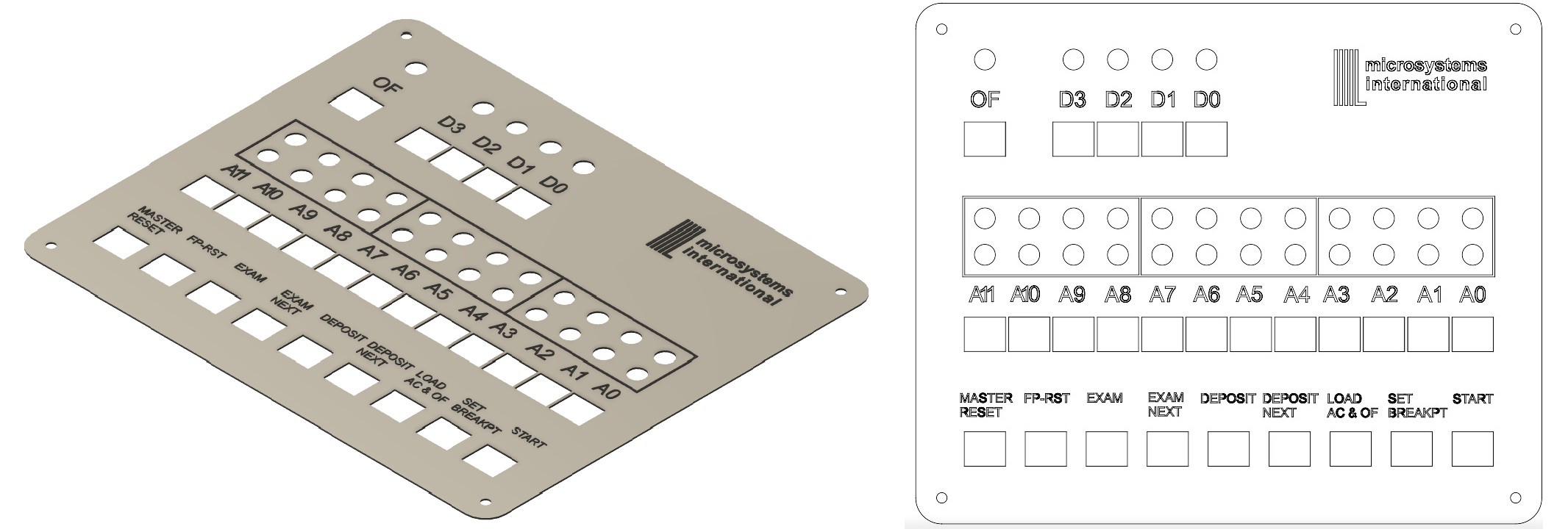
In the end I had them produced professionally based on the image and DXF file I sent them (pictured above), and was surprised at how inexpensive it was (about $50).
The Case
When I asked Zbigniew what he though the project enclosure should look like he suggested the Hammond 1401G.
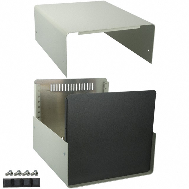
We could have purchased one but based on the dimensions obtained from the Hammond web site I was able to model and print one instead. The case literally filled the print volume of my Prusa MKS3S+.
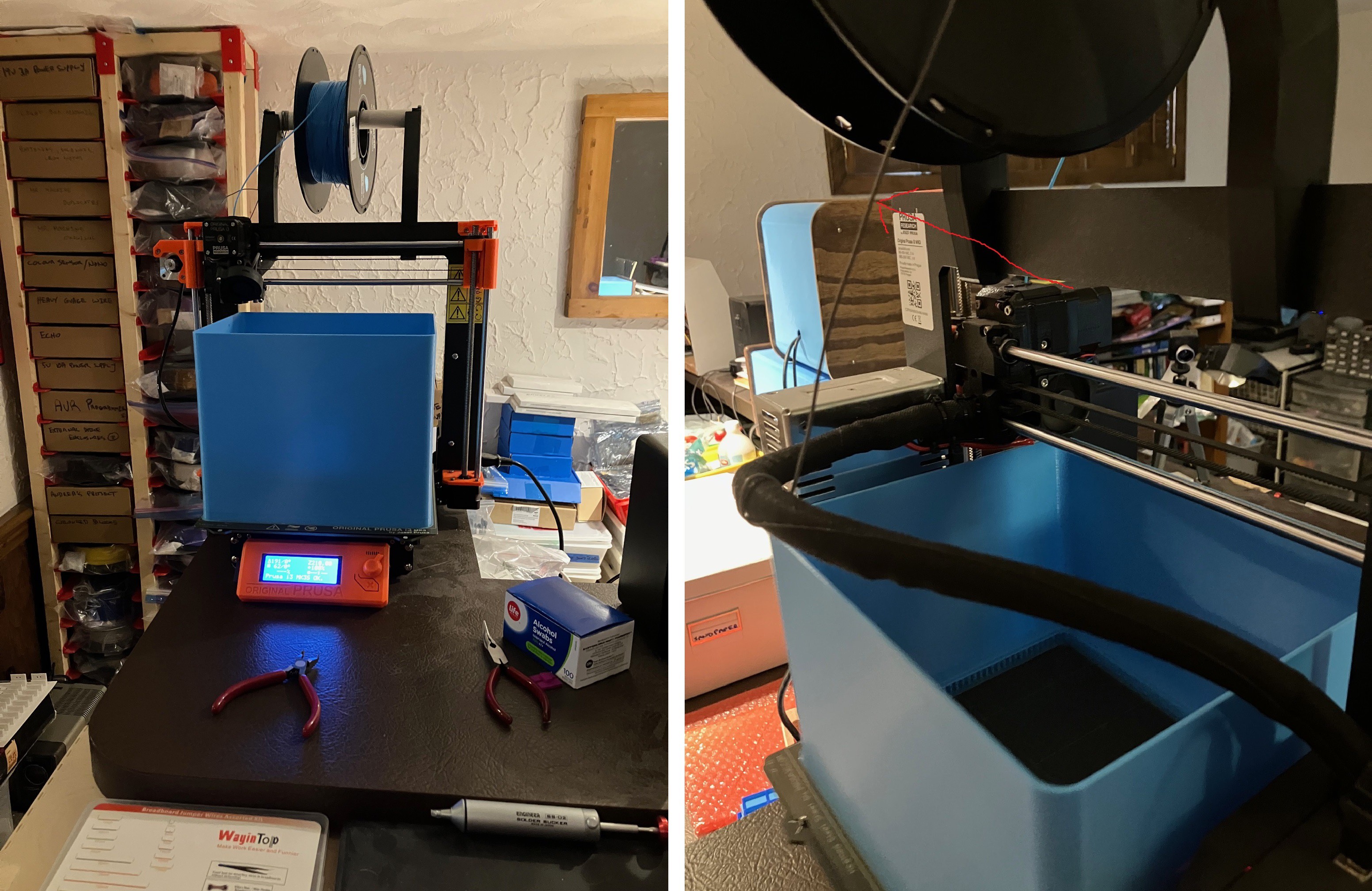
In the end I think it turned out pretty well. I love the blue which was a popular color back in the 70s (THINK Big Blue).
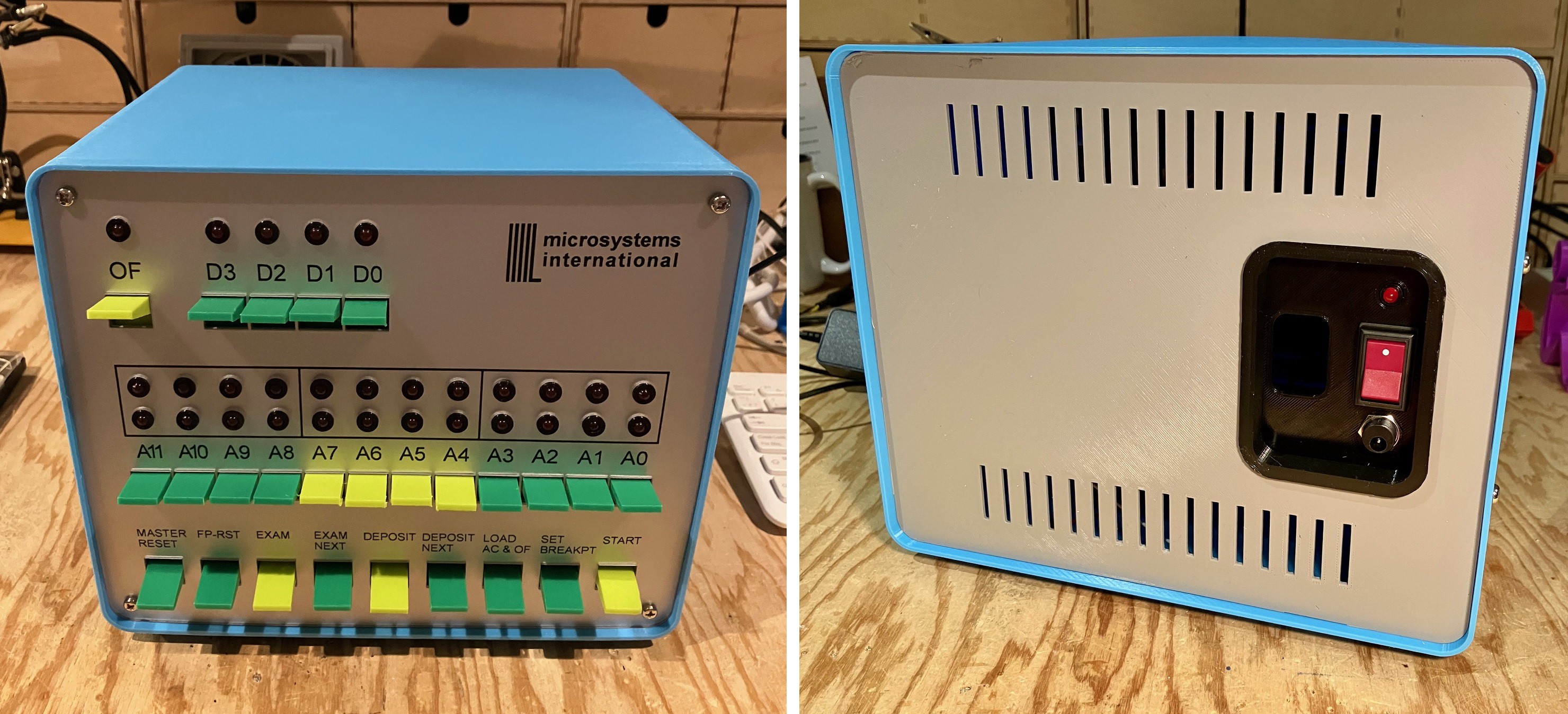
The back panel was based on the Hammond design with a custom power switch insert added.
Wiring the Front Panel
The heart of this CPS-1 reproduction is a Raspberry Pi 4. In addition I used an IO extender "hat" which adds 32 IO pins to the existing Pi GPIO pins that are accessible via an 3-wire I2C interface.
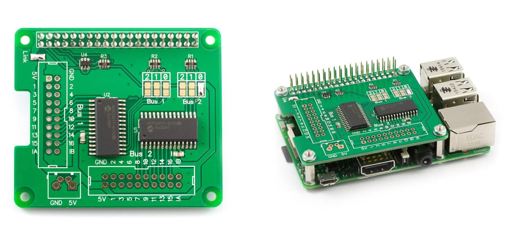
With the additional IO pins I could assign a pin to each of the 26 switches and 29 LEDs on the Front Panel. I could have setup the switches into an array and polled the switch status (like a keyboard) and similarly multiplexed LED arrays to reduce the overall IO count considerably, but these techniques add significant complexity to the software and for the cost of the extender (about $21) are not worth the effort.
Having said that I got to work wiring up the switches and LEDs.
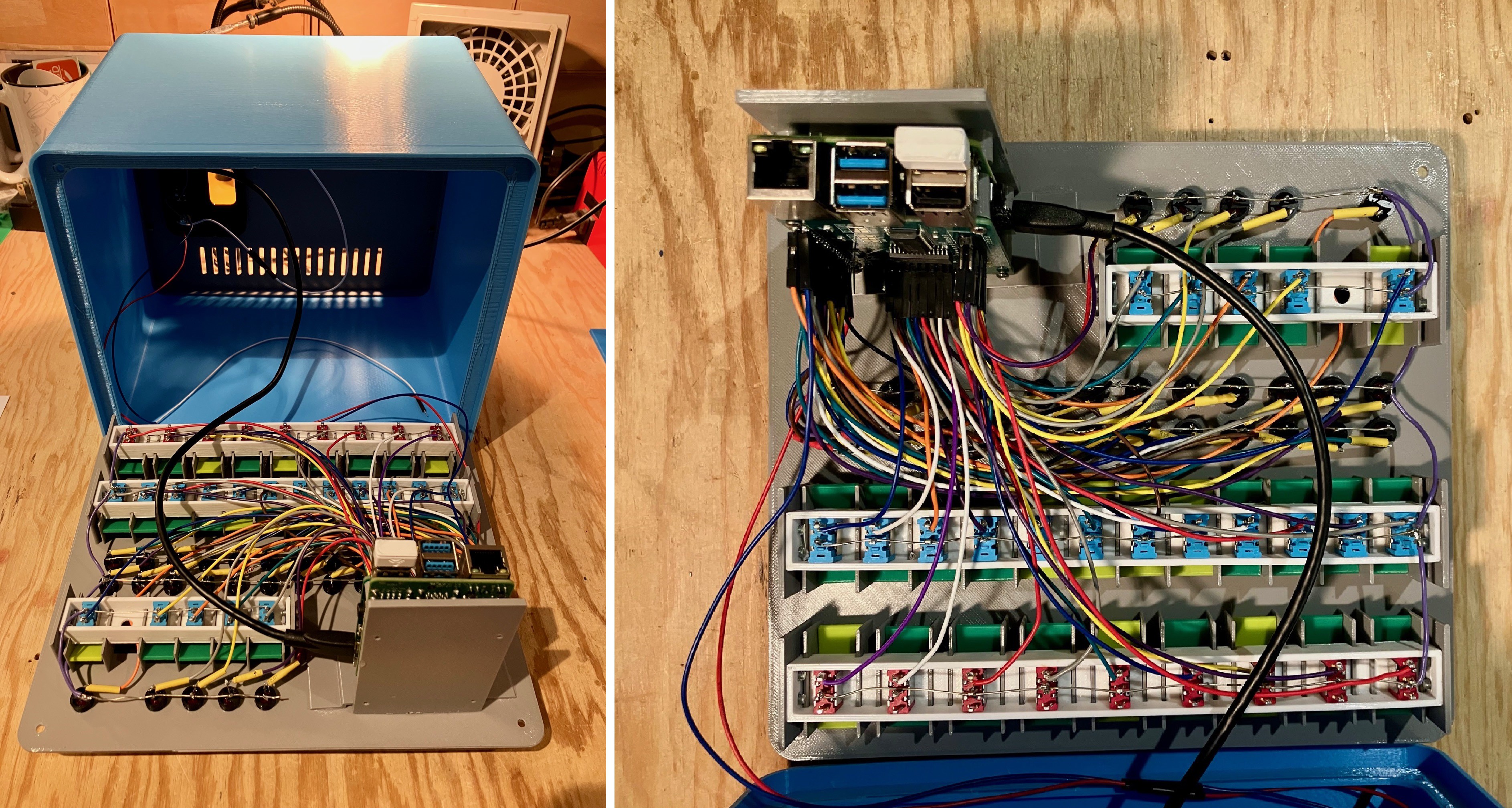
Can you say spaghetti? I know it looks a bit messy. If I were making a bunch of these I would have considered this version a beta/proof of concept and gone on to rework the front panel using a proper PCB for version 2. However, since I was only making a couple, I though all that extra work would be wasted (except maybe to scratch that little anal retentive part of me).
At any rate here are all the pin assignments:
LED Pin Assignments
===================

LED         Pi Pin
~~~         ~~~~~~
A0-Bottom   15
A0-Top      14
A1-Bottom   17
A1-Top      18
A2-Bottom   27
A2-Top      22
A3-Bottom   23
A3-Top      24
A4-Bottom   10
A4-Top      9
A5-Bottom   25
A5-Top      8
A6-Bottom   11
A6-Top      7
A7-Bottom   1
A7-Top      0
A8-Bottom   5
A8-Top      12
A9-Bottom   6
A9-Top      13
A10-Bottom  16
A10-Top     19
A11-Bottom  20
A11-Top     26
OFLOW       21

LED         Extender Pin
~~~         ~~~~~~~~~~~~
D0          Bus2 16
D1          Bus2 15
D2          Bus2 14
D3          Bus2 13


Switch Pin Assignments
======================

Switch          Extender Pin
~~~~~~          ~~~~~~~~~~~~
A0              Bus1 1
A1              Bus1 2
A2              Bus1 3
A3              Bus1 4
A4              Bus1 5
A5              Bus1 6
A6              Bus1 7
A7              Bus1 8
A8              Bus1 9
A9              Bus1 10
A10             Bus1 11
A11             Bus1 12

START           Bus1 13
SET BREAKPT     Bus1 14
LOAD AC&OF      Bus1 15
DEPOSIT NEXT    Bus1 16

DEPOSIT         Bus2 1
EXAM NEXT       Bus2 2
EXAM            Bus2 3
FP-RST          Bus2 4
MASTER RESET    Bus2 5

D0              Bus2 6
D1              Bus2 7
D2              Bus2 8
D3              Bus2 9
OF              Bus2 10
Integrating the Front Panel
Getting the HW Front Panel to work with the Emulator was fairly straight forward. The default Raspberry Pi OS image has the pigpio library pre-installed. Pigpio allows applications to access the Pi's HW GPIO pins (provided the application is running as root).
So in the emulator C code, wherever GUI switches were being "read" or GUI LEDs are being "toggled" I added corresponding and parallel calls to the pigpio library to do the exact same thing with the HW front panel. Since the York University code was extremely well structured this was not difficult.
Wrapping Up
It was a lot of fun creating the CPS-1 reproduction. I enjoyed working with Ziggy trying to deduce what the CPS-1 might have looked like. Regardless of how close we got with the "look", with the backing of the excellent York University Computer Museum (YUCoM) software based CPS-1 emulator, this is certainly going to be an excellent "work a like" device.
I'm looking forward to meeting with Ziggy next month to deliver the CPS-1 reproduction for inclusion at the York University Computer Museum.
 Michael Gardi