 Arnov Sharma
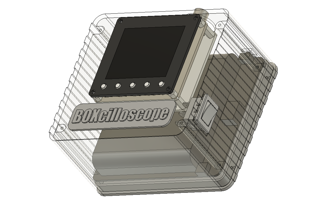
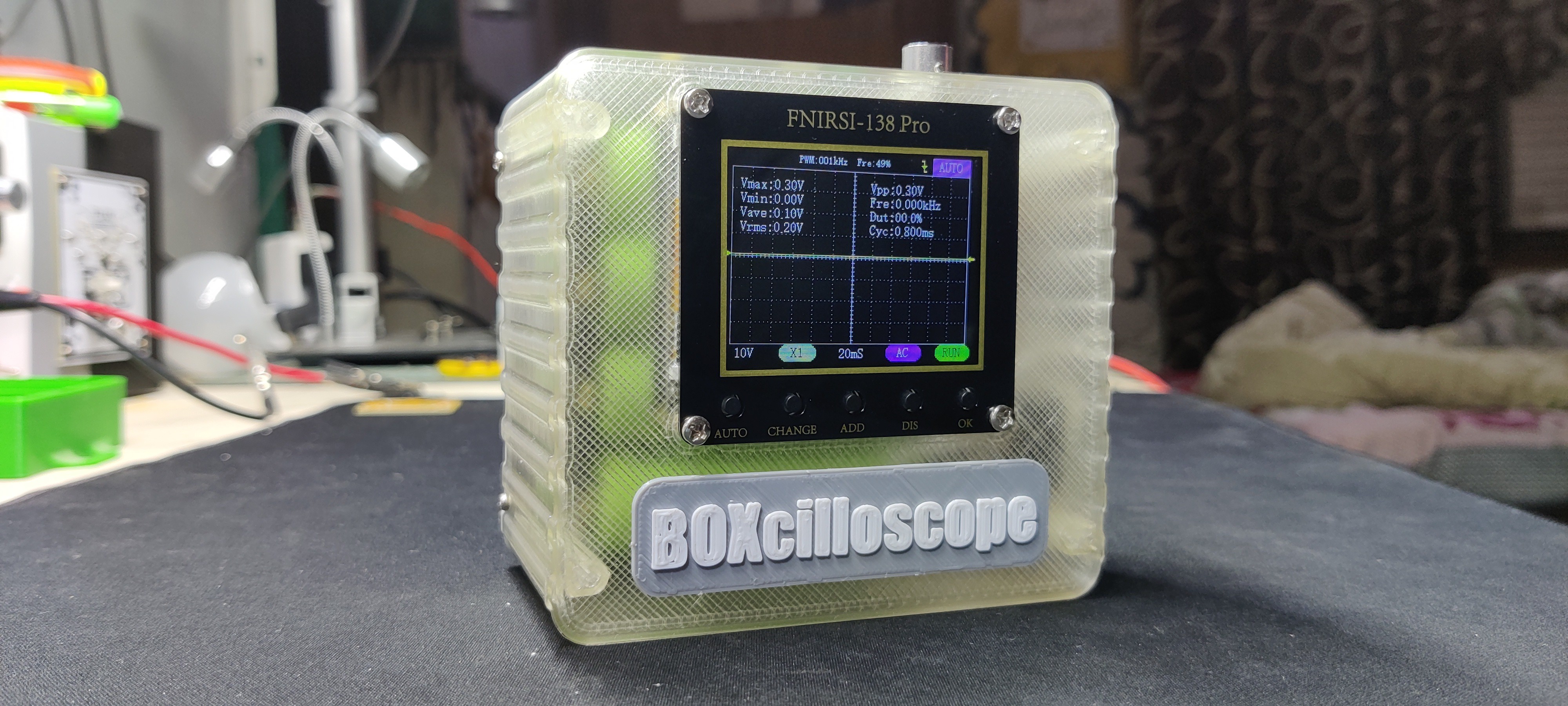
We used Fusion360 to create and build the model, and we 3D printed the parts using gray and transparent PLA.
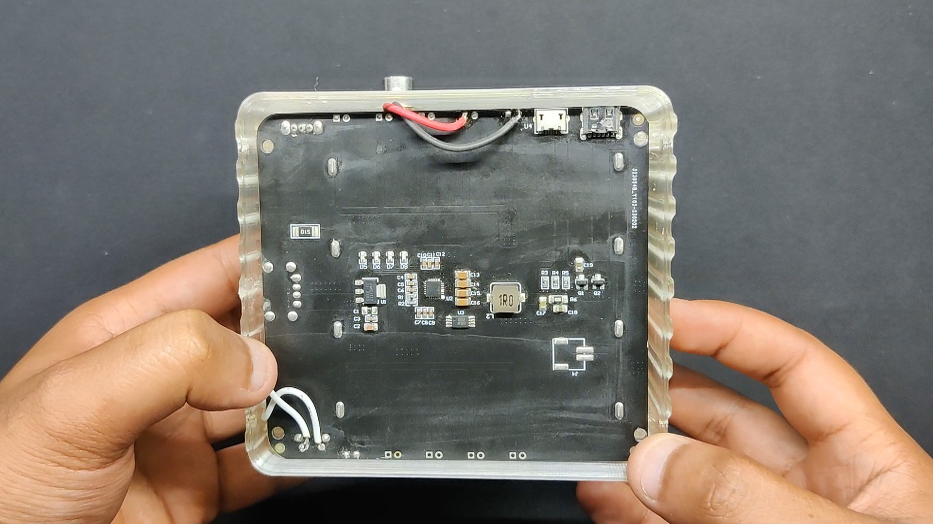
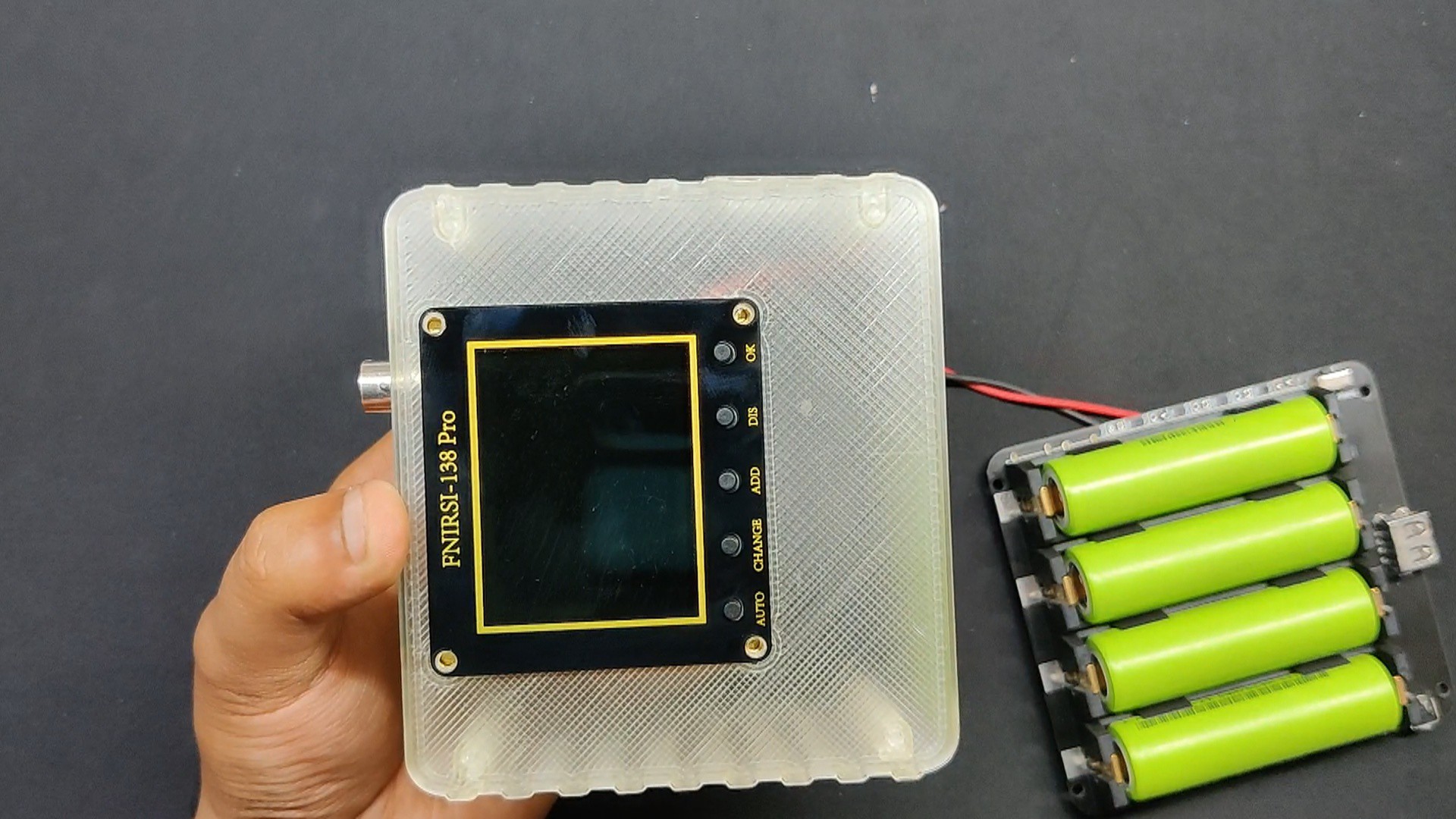
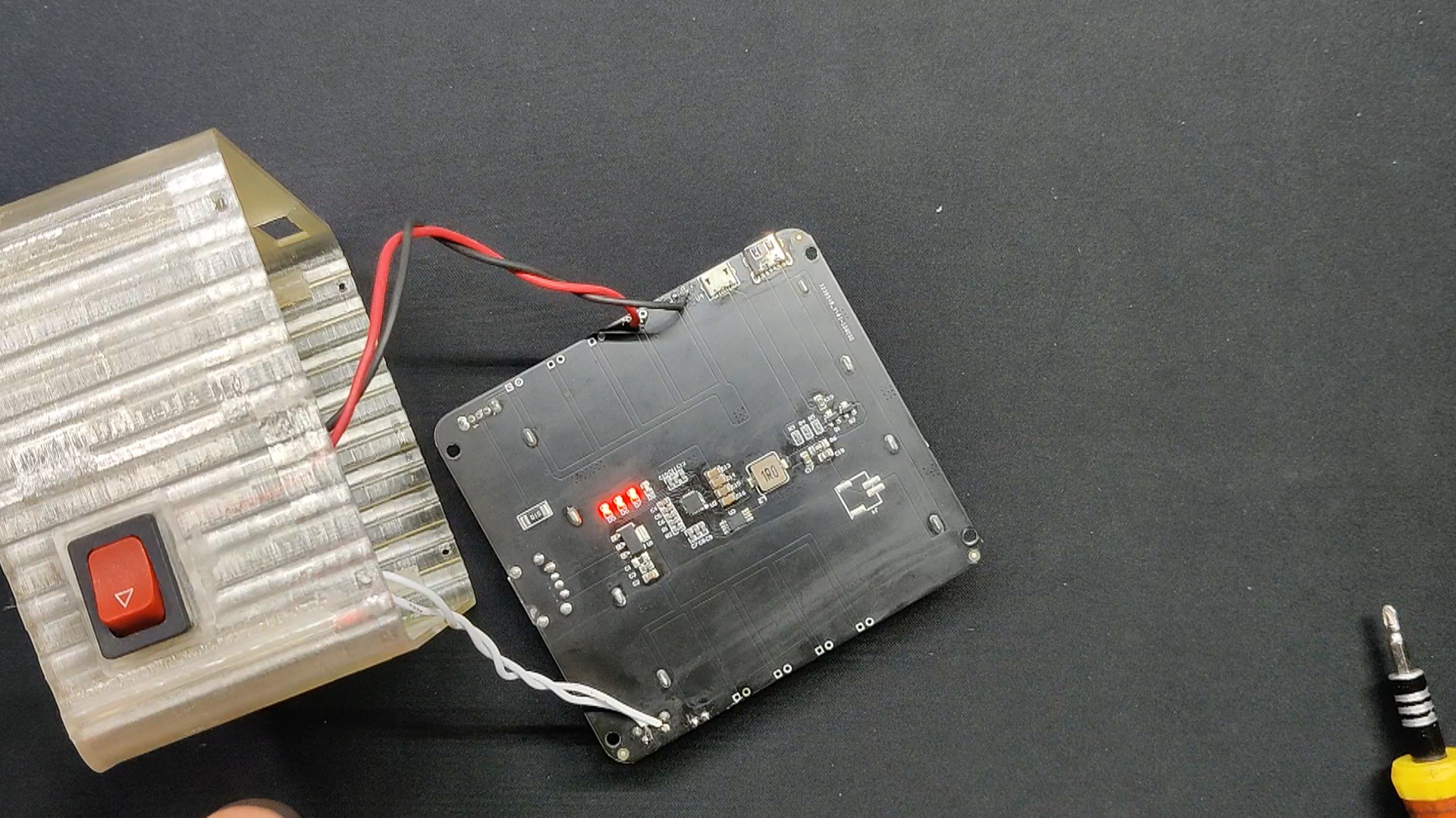
Inside the device, there is a power module that uses four parallel lithium-ion cells to boost the voltage of the cells from 3.7V to 5V and generate a steady 3A current. Furthermore, PCBWAY provided the oscilloscope and power module for this project.
This article is about the complete build process of this project so let's get started with the build.
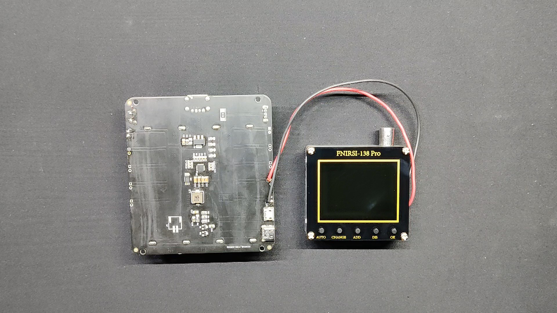
Digital Oscilloscope: FNIRISI 138 Pro
The oscilloscope is an electronic test instrument that graphically displays varying voltages of one or more signals as a function of time. It’s a crucial tool for debugging, analyzing, and characterizing electrical signals.
Purchasing a high-quality oscilloscope is an expensive endeavor.
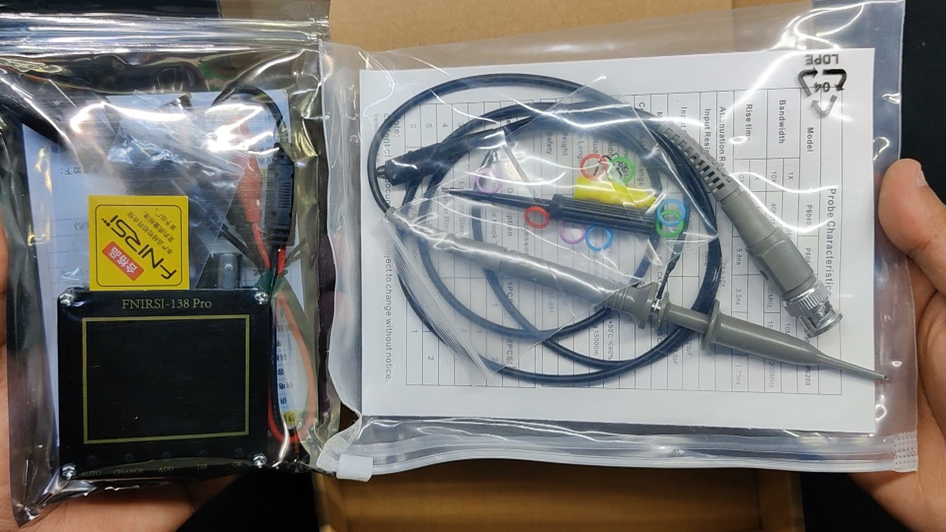
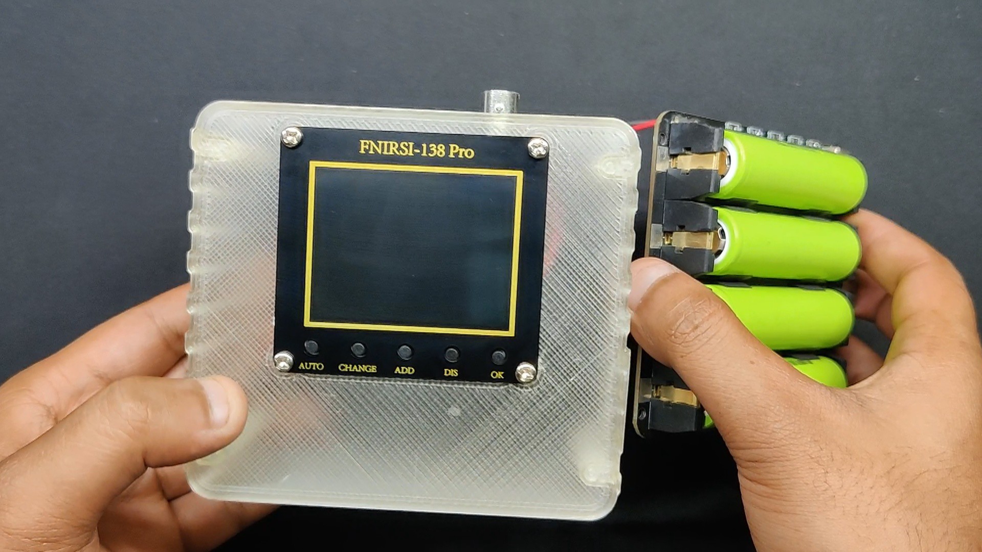
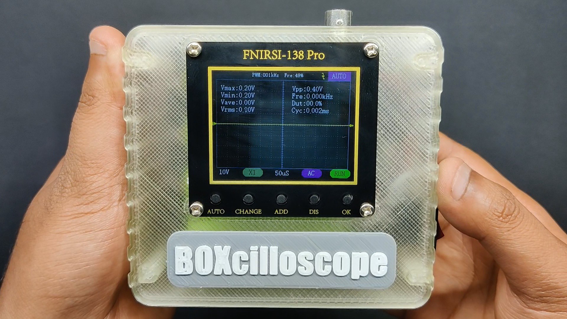
For basic testing, I got the FNIRISI-138 Pro, a portable, handheld digital oscilloscope meant for both enthusiasts and pros, rather than shelling out a fortune for an oscilloscope that I would use maybe once or twice every six months. It has a 200 kHz bandwidth and a real-time sampling rate of 2.5 MSa/s.
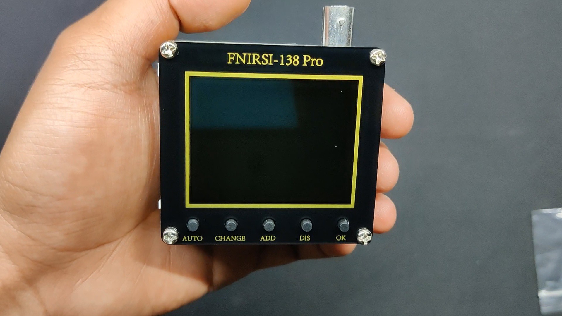
Waveforms can be easily viewed on this device's 2.4-inch high-definition LCD screen. It is capable of measuring voltages up to ±400V and supports many trigger settings (single, normal, and automatic).
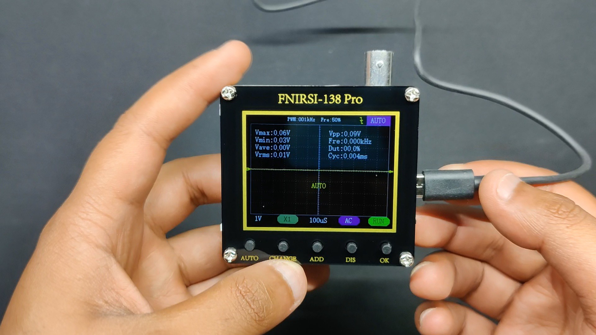
Additionally, it includes an efficient one-key AUTO function for quick waveform display without complex adjustments.
Technical Specifications-
- Operating Voltage: 5-6V
- Sampling Rate: 2.5MS/s
- Bandwidth: 200kHz
- Vertical Sensitivity: 10mV/Div-20V/Div (in 1-2-5 increments)
- Horizontal Time Base Range: 10µs/Div-20V/Div (in 1-2-5 increments)
- Voltage Range: X1 Probe ±40V, X10 Probe ±400V
- Trigger Modes: Auto/Normal/Single
- Coupling Mode: AC/DC
- PWM Output: 3.3V, F.R:0~80kHz, Duty Cycle: 0~100>#/li###
- Show: 2.4 in/PPI:320*240
- Size: 66*71.6*22.8mm
- Weight: 53g
PCBWAY GIFTSHOP
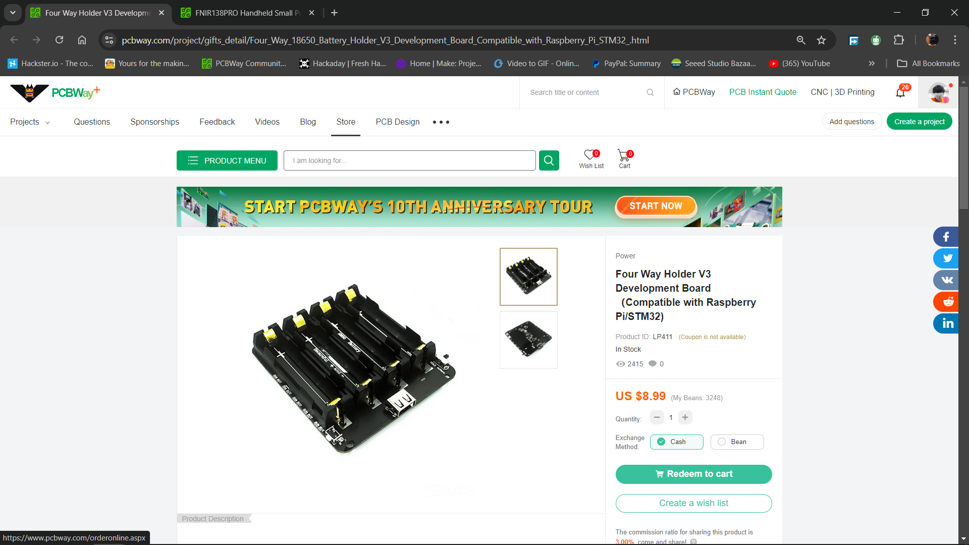
As for sourcing this Handheld oscilloscope, we got it from PCBWAY's Giftshop.
PCBWAY gift shop is an online marketplace where you can get a variety of electronics modules and boards for their genuine price, or you could use the PCBWAY currency, which is called beans.
You get beans after ordering something from PCBWAY as reward points, or you can also get them by posting any project in the PCBWAY community.
They are presently celebrating their tenth anniversary in business by hosting a tour that includes a few activities in which you can take part and win some goodies, such as special coupons and the chance to open blind boxes filled with merchandise from their gift shop.
Over the past ten years, PCBWay has distinguished itself by providing outstanding PCB manufacturing and assembly services, becoming a trusted partner for countless engineers and designers worldwide.
Their commitment to quality and customer satisfaction has been unwavering, leading to significant growth and expansion.
You guys can check out PCBWAY if you want great PCB service at an affordable rate.
DESIGN
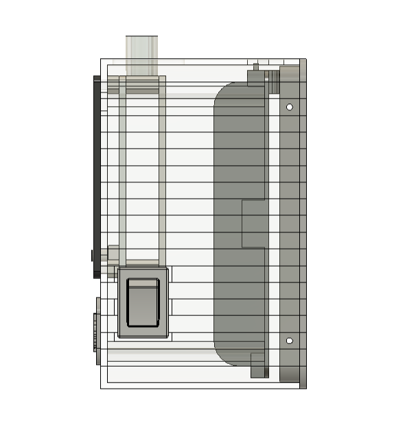
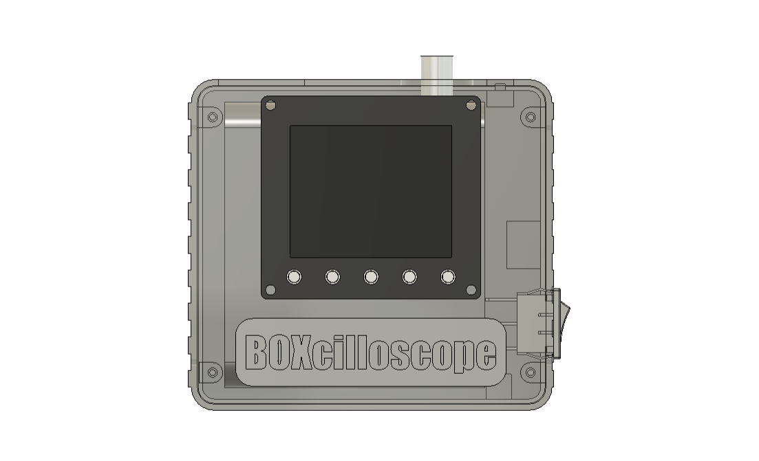

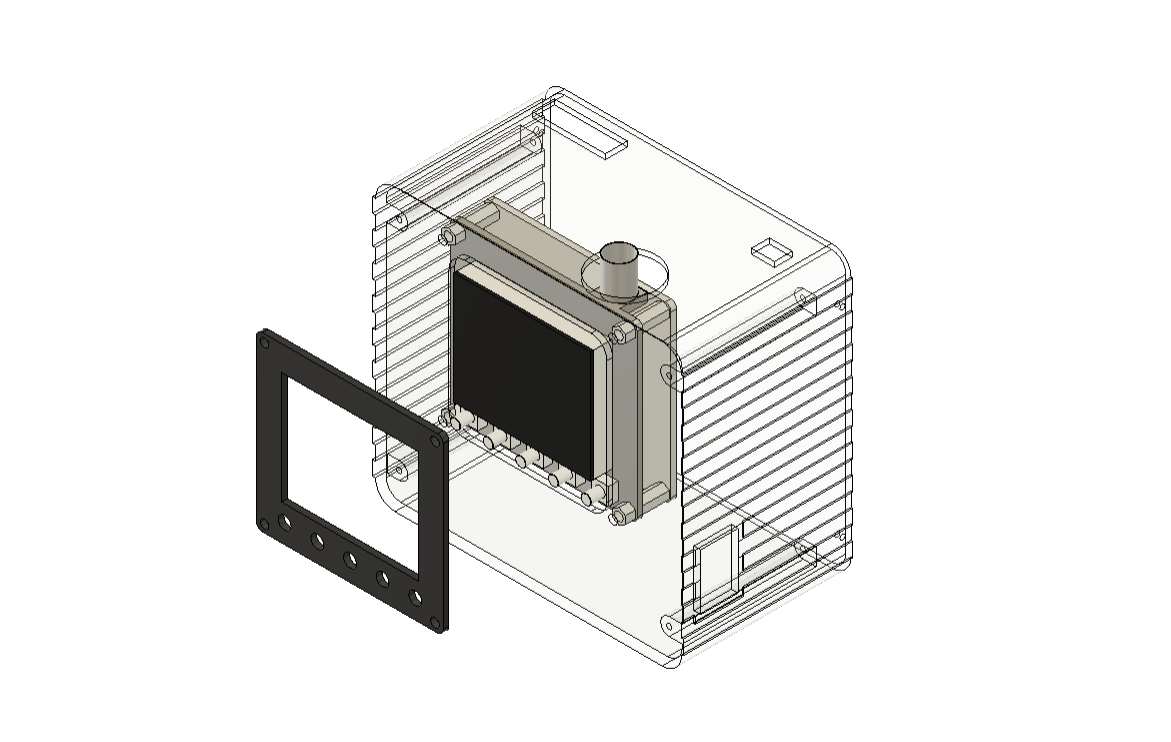
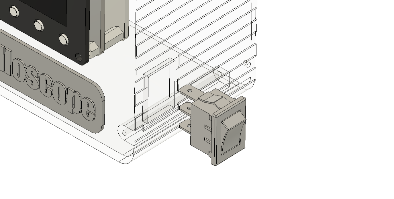
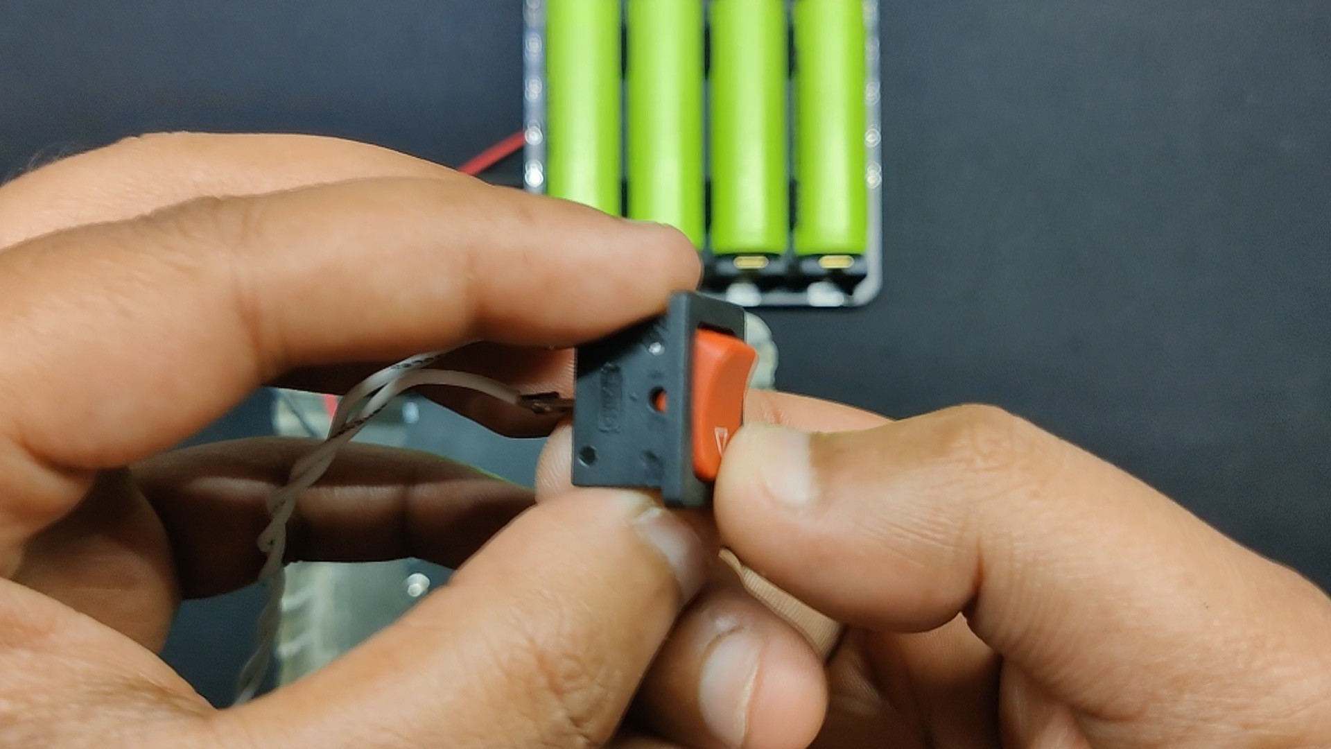
In order to design this project, the oscilloscope needs to first be modeled. All necessary components, such as the power module and rocker switch, have to be imported into the model.
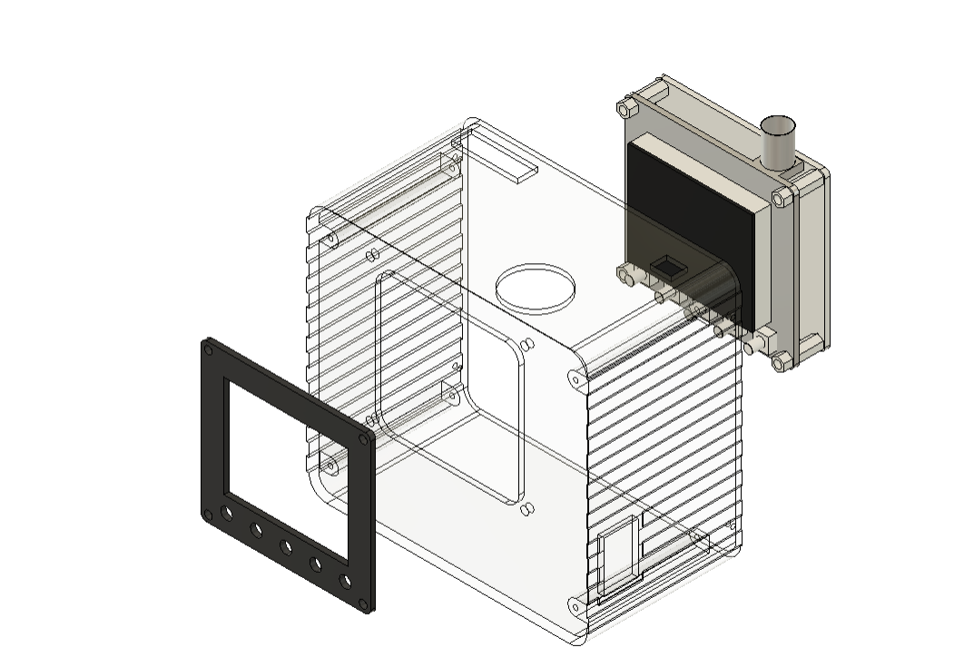
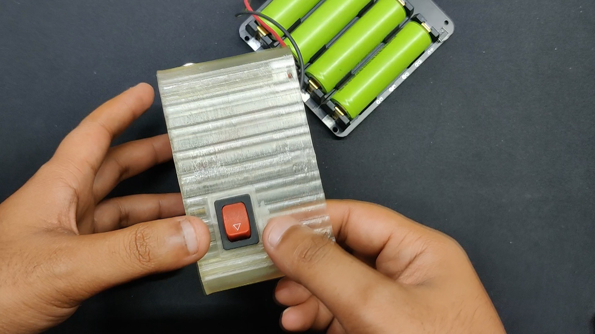
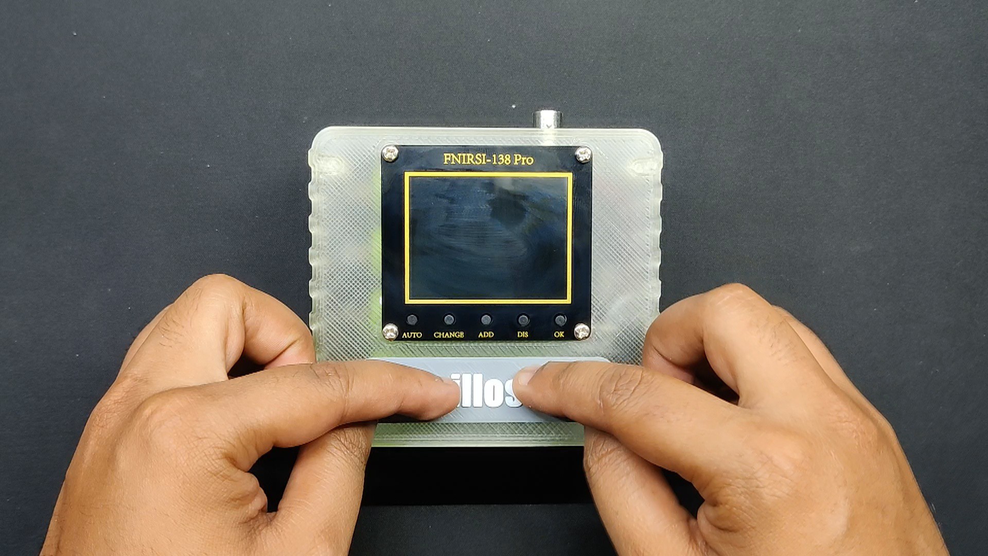
The prepared model was made up of two primary parts: the main body that holds the scope in place, along with the side rocker switch, and the power module. The second part covers the model's back side and is called the lid.
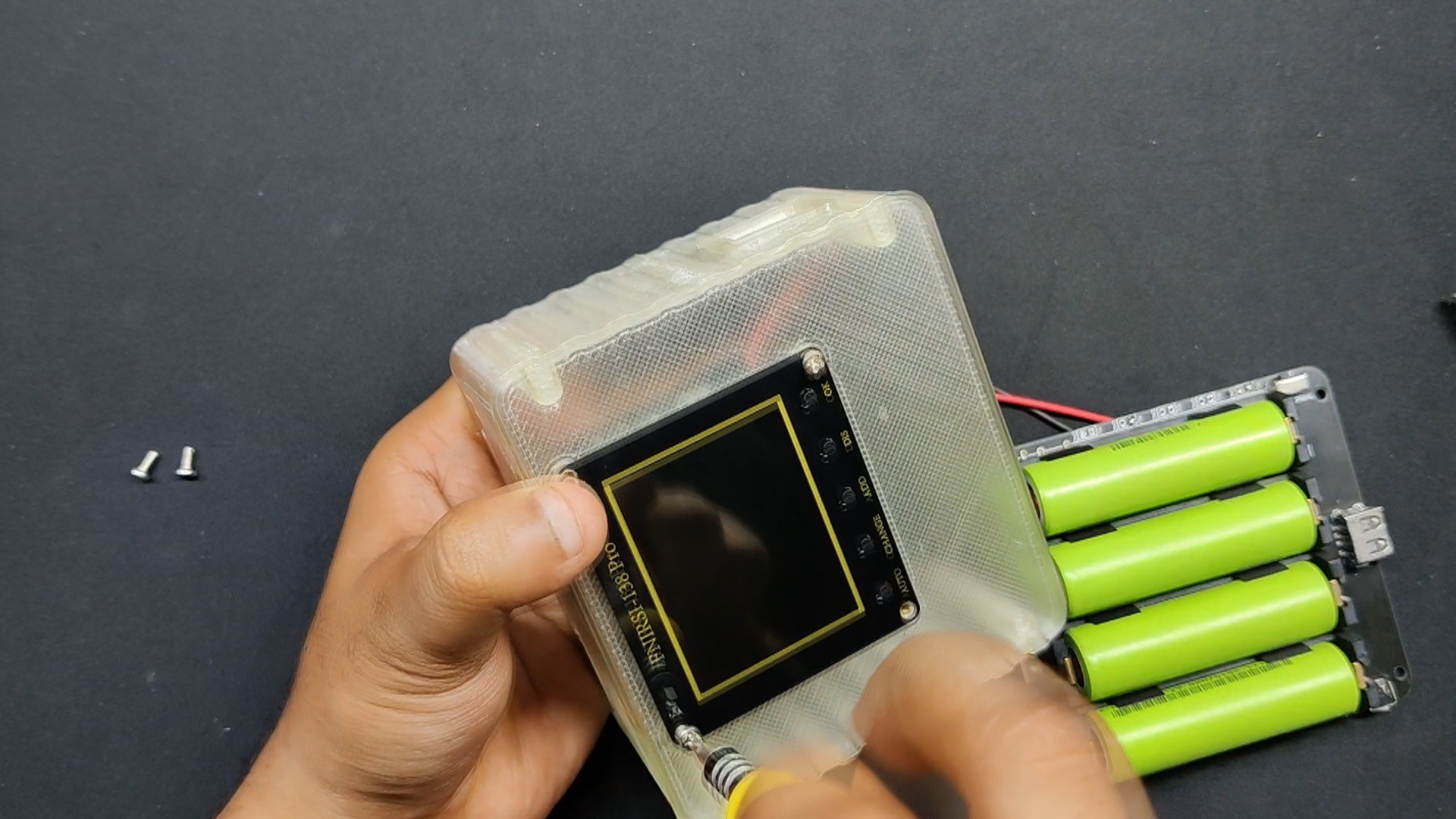
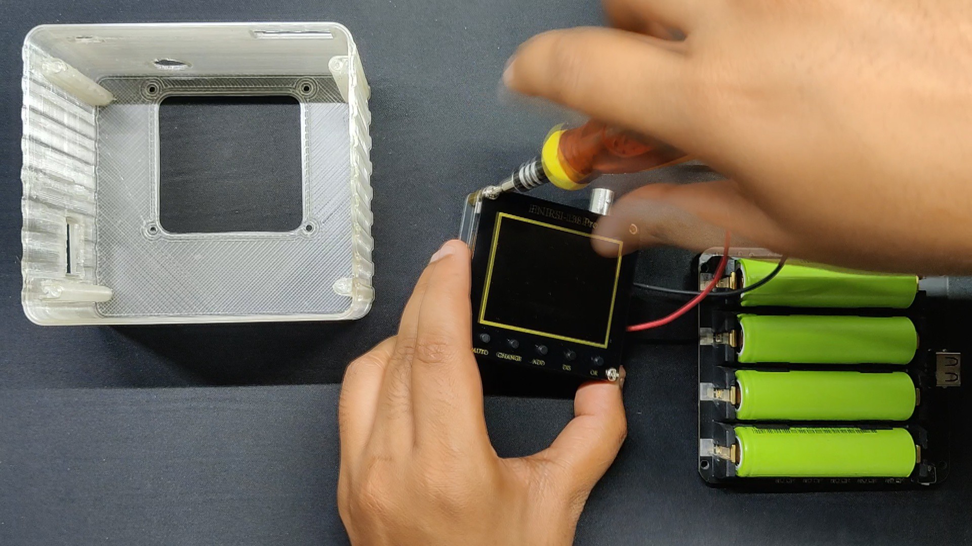
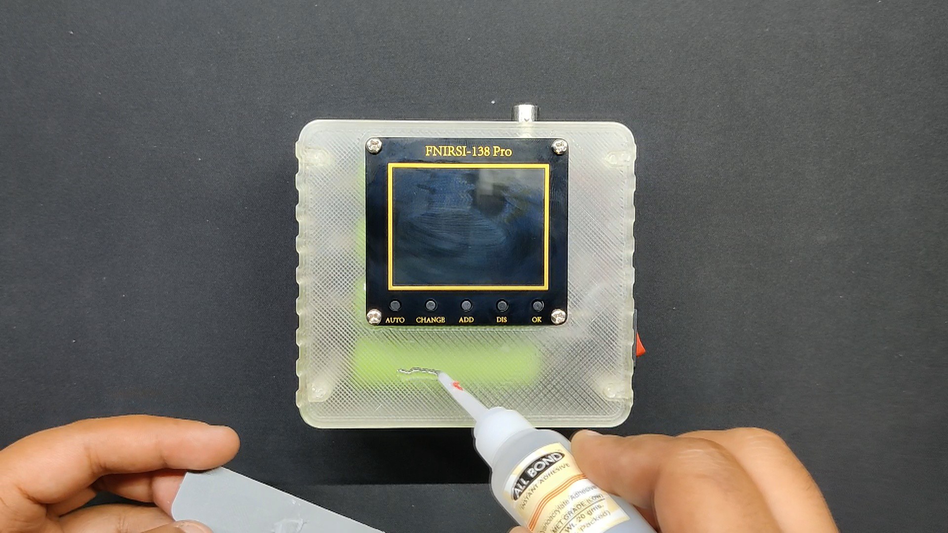
We created the model so that the topmost PCB layer of the oscilloscope would be added on the front side, and the body would be sandwiched between the first and second layers of the oscilloscope. This way, we can easily mount the scope in place using the four M3 bolts with the PCB standoffs. The oscilloscope is made up of three PCB layers joined together using PCB standoffs.
Four M2 screws are used to mount the power module inside the main body.
On the left side of the main...
Read more »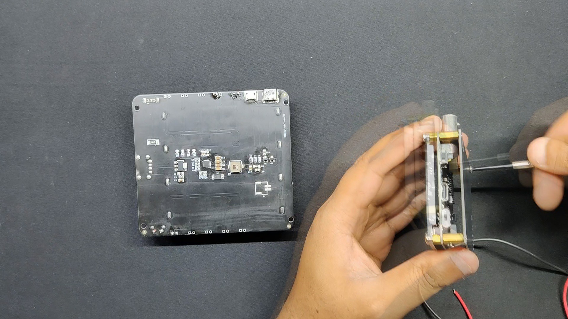


 Enrique
 Joe Menard
 Mile
Mile