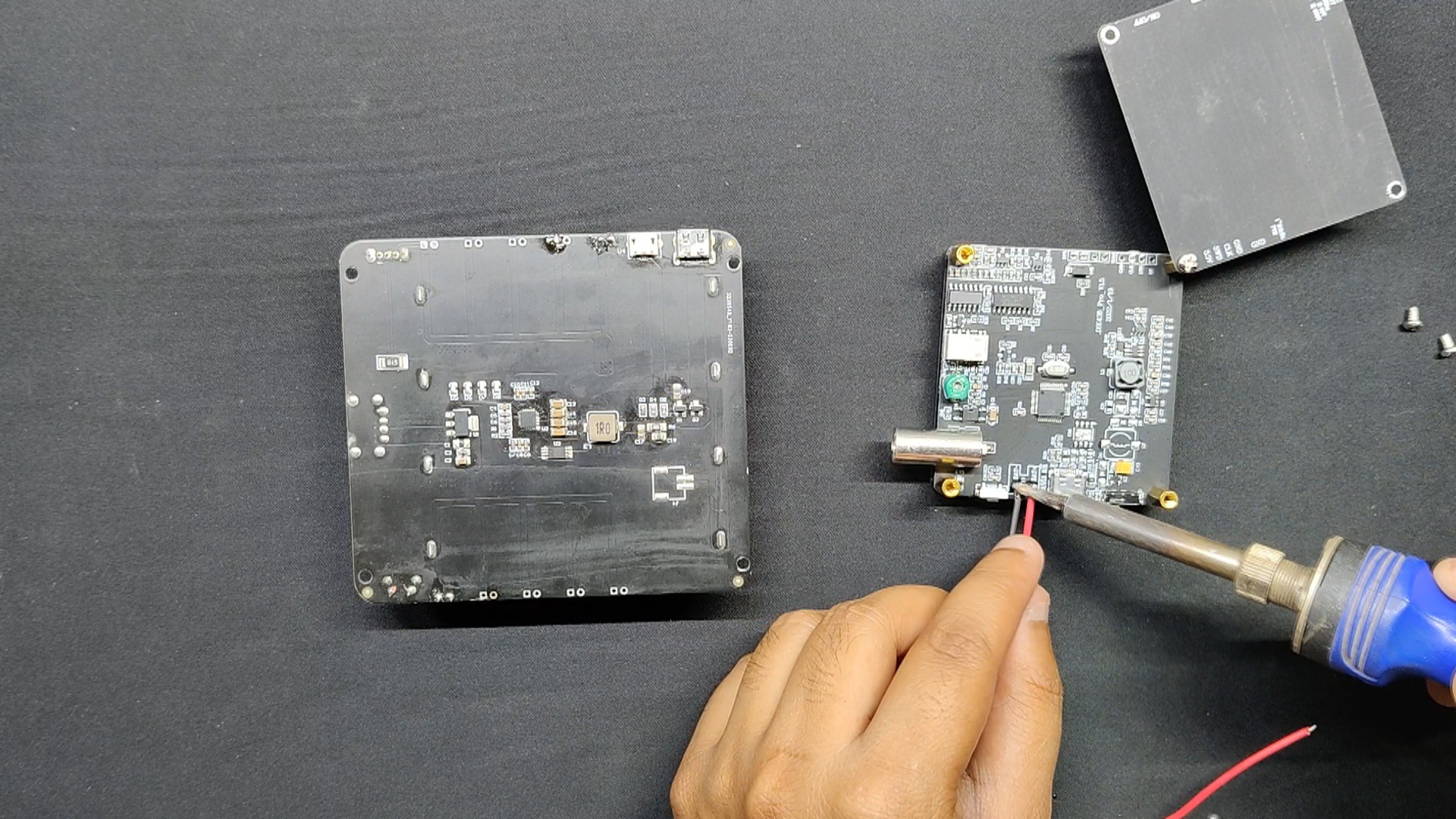
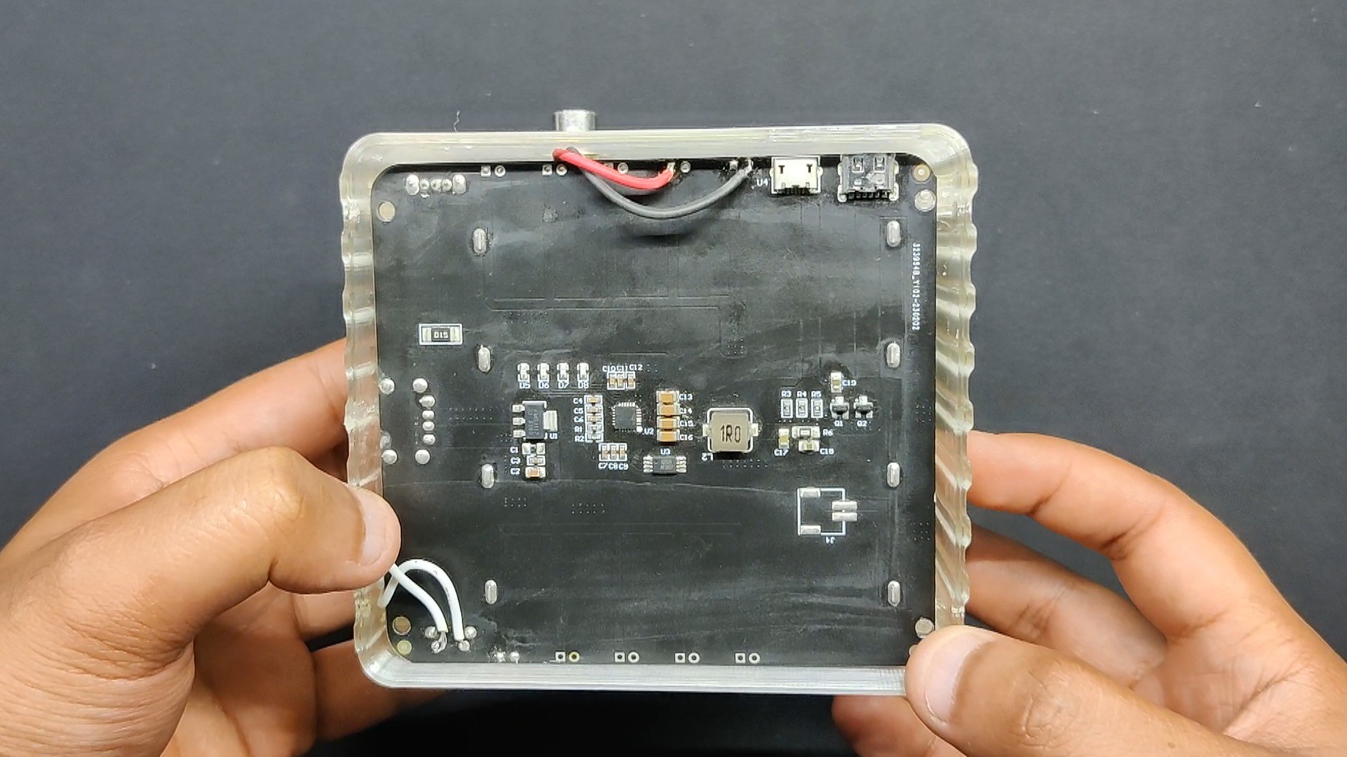
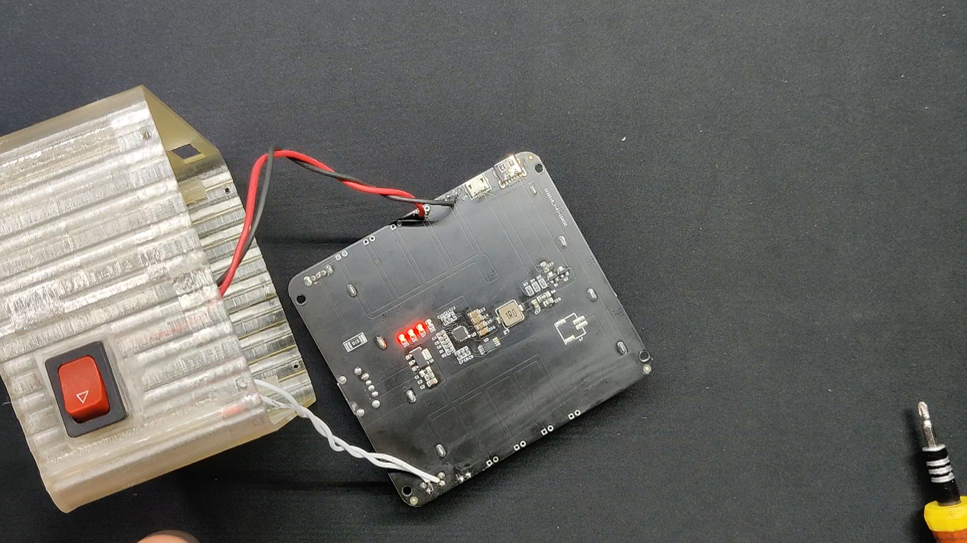
Prior to starting the assembly of the power module, we unscrewed the M3 bolts to access the scope's backside PCB.
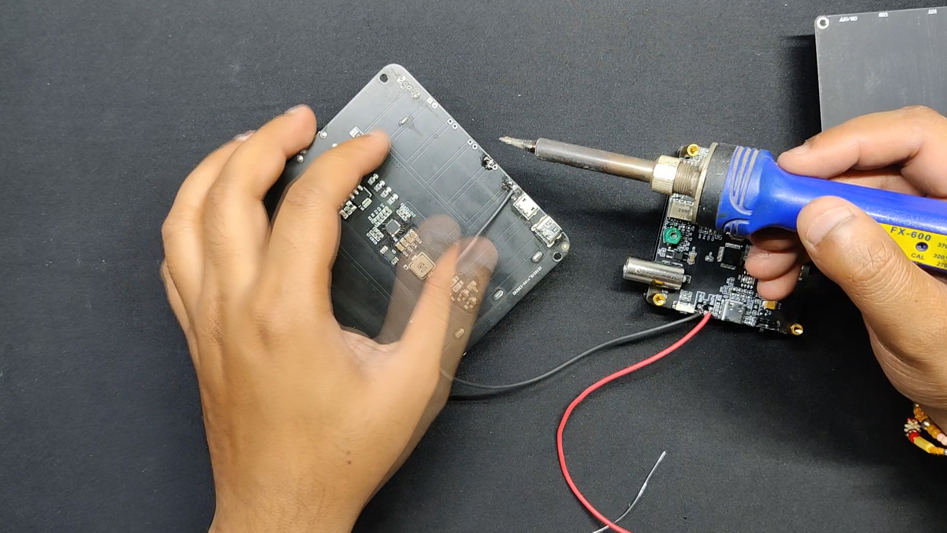
The battery connectors are located here, and we can supply 5V to 9V to power this device. We soldered connecting wires to the battery's CON2 connector, which is subsequently linked to the 5V and GND terminals of the power module.
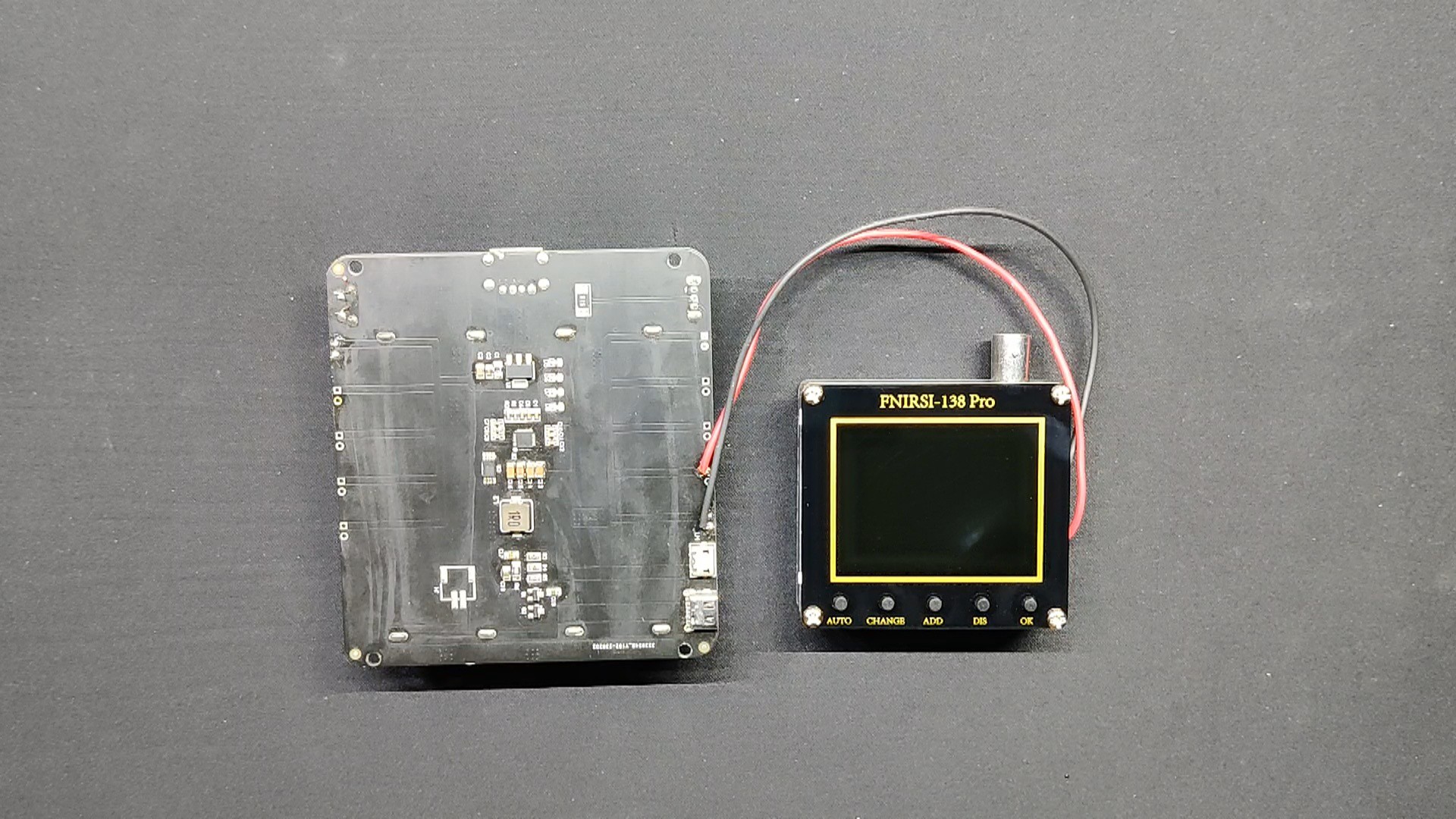
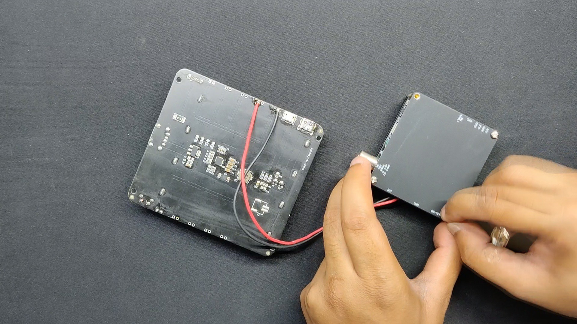
Next, we added the scope's backside PCB in its place.
When the power module's push button is pressed, the scope turns on, indicating that the setup is working.
2
FINAL ASSEMBLY
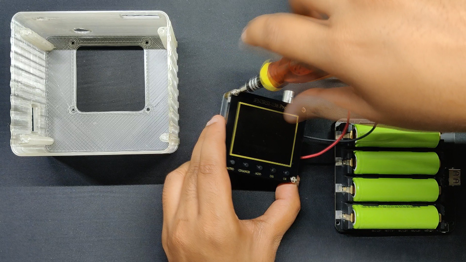
The final phase in the assembling process is to remove the scope's top layer, which is fastened in place by four M3 bolts.
After that, we align the mounting holes on the scope with the mounting holes on the main body by positioning the assembly scope inside the body.
After aligning the top layer of the scope with the body's mounting holes, we place the top layer on the front side of the main body and fasten it securely to the M3 bolts.
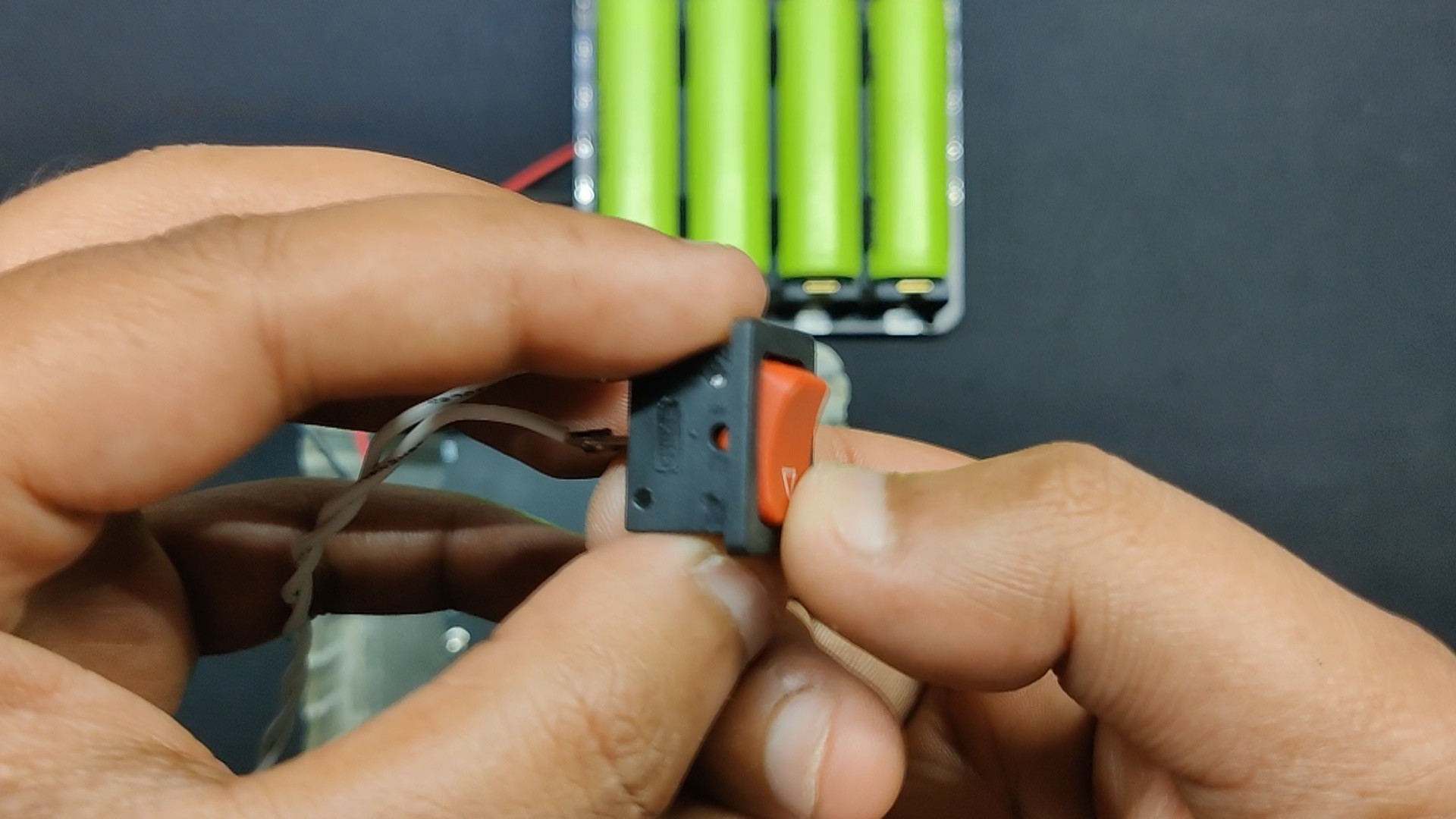
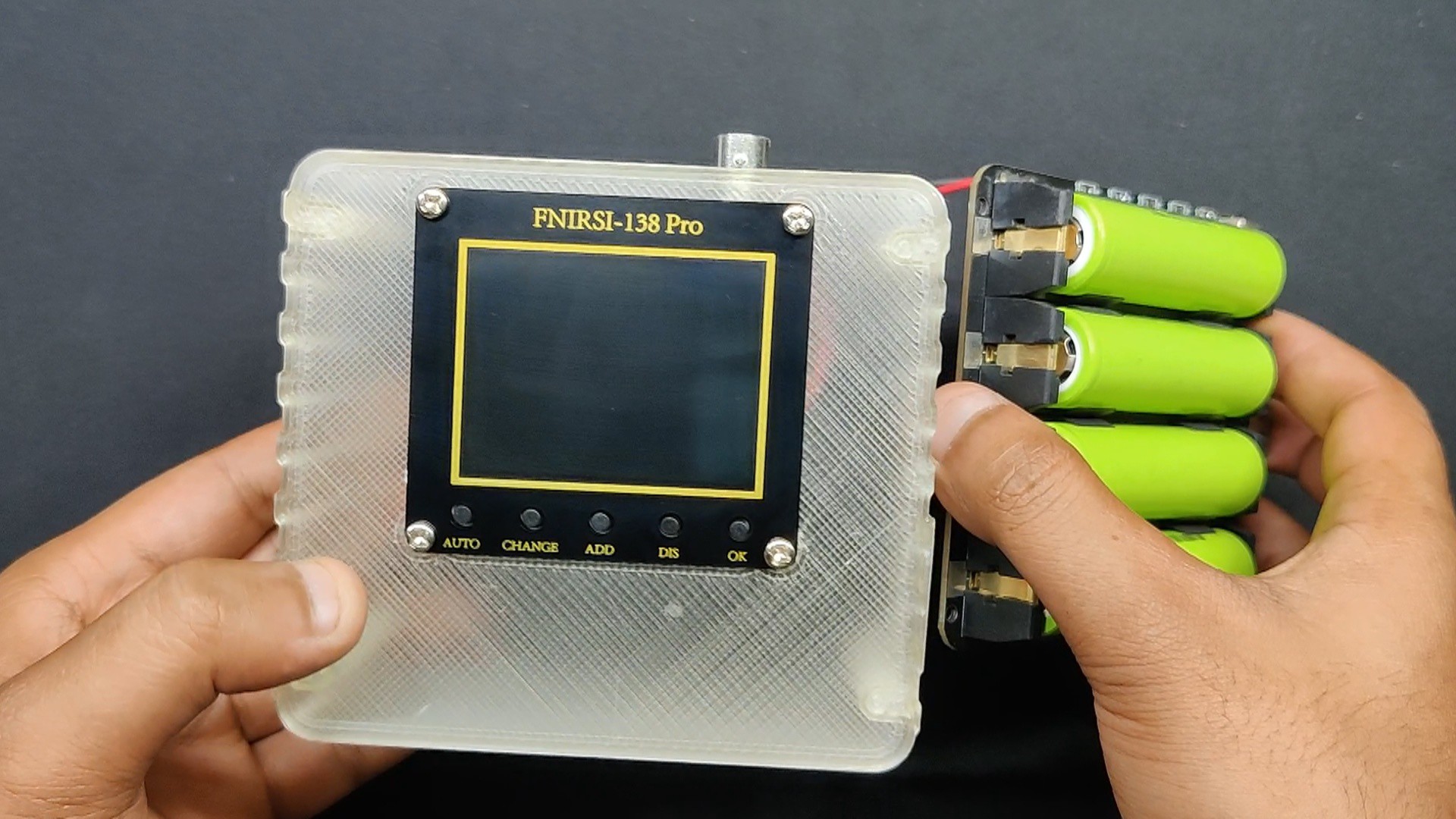
The push button, which resemble a rocker switch, is then pushed into the designated slot on the left side of the main body.
Next, we linked the push button terminals on the power module to the push button terminals on the buttons; these two buttons will be wired in parallel.
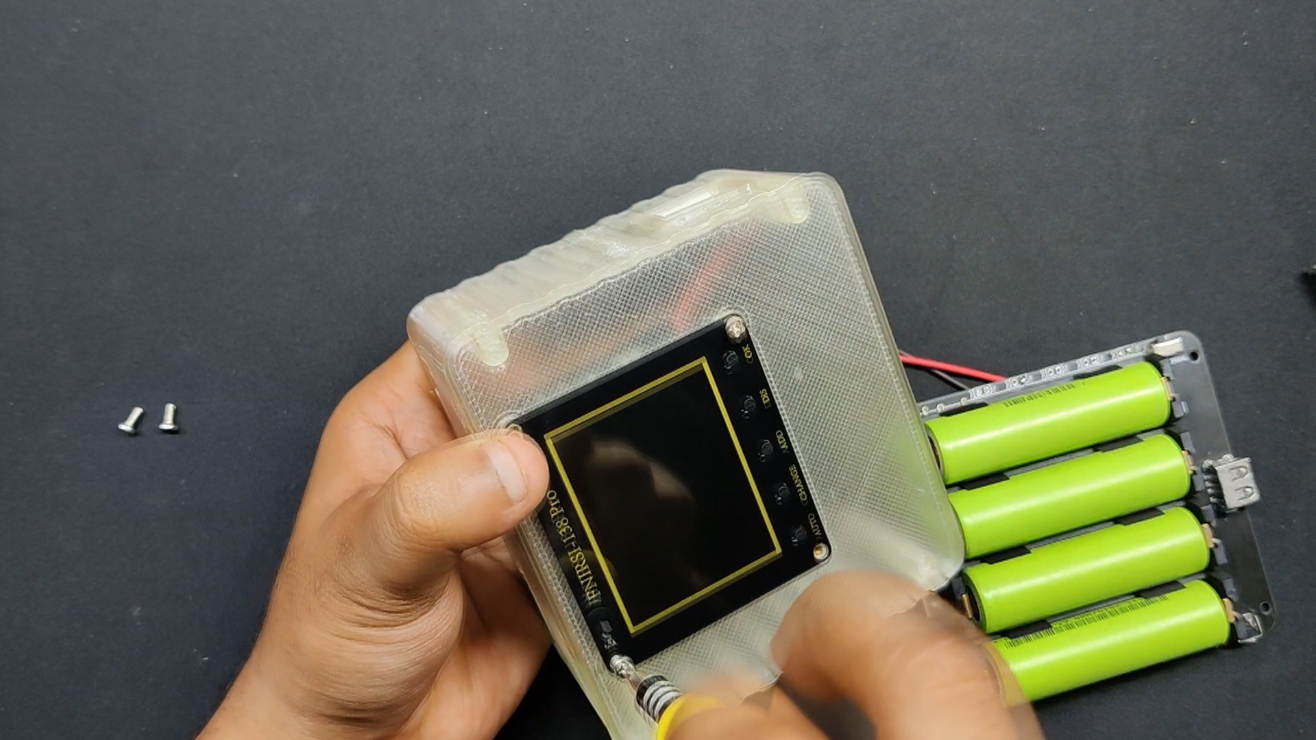
After positioning the power module within the main body, we fasten it inside with four M2 screws.
After that, the lid part is positioned on the back and fastened using M2 screws.
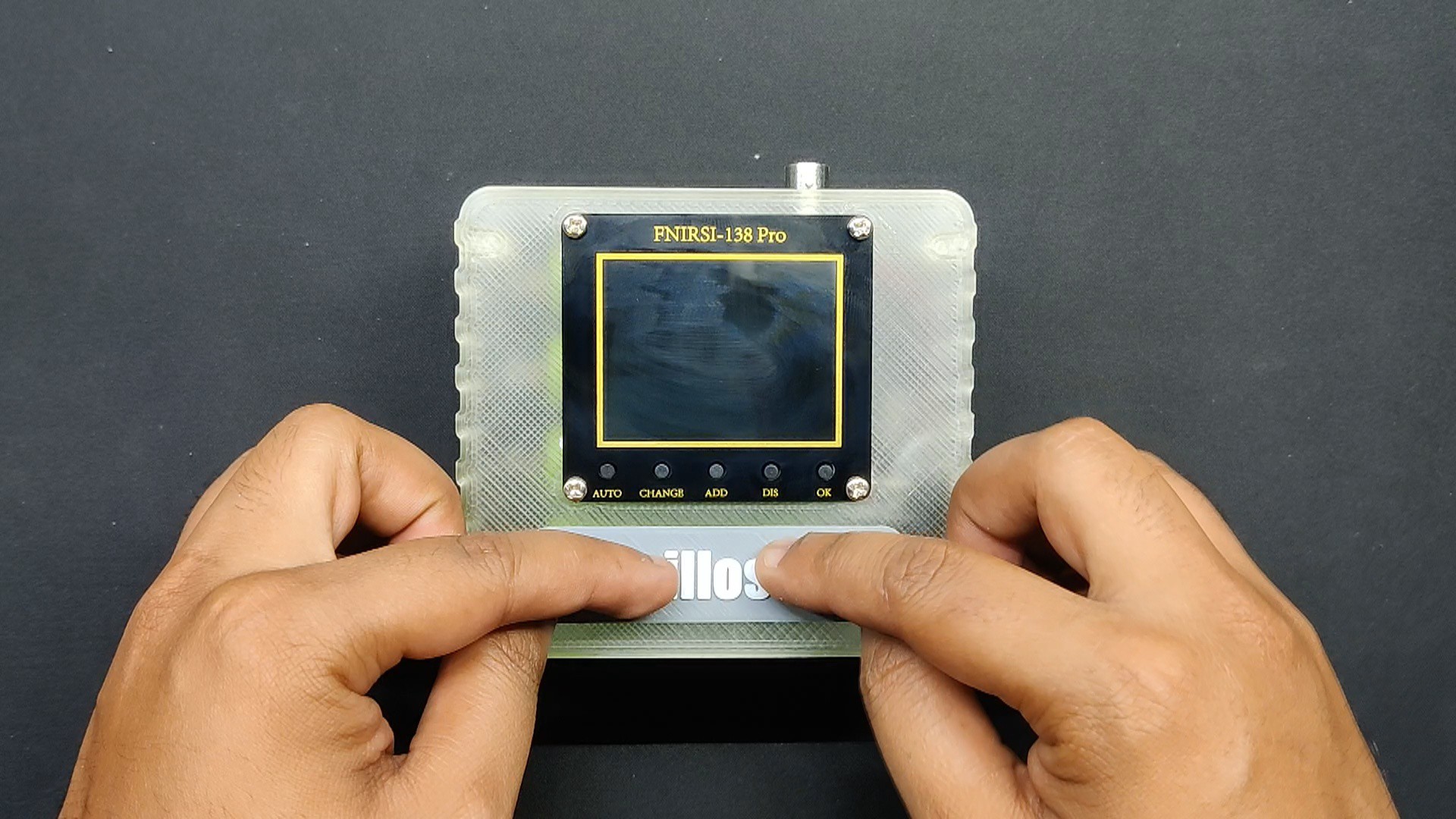
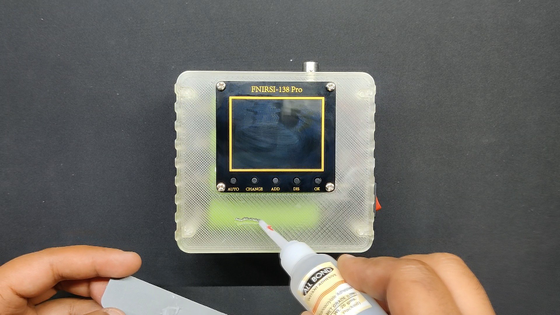
Next, we attached the nametag to the front side of the screen by first gluing the nametag to the surface and then moving it into position.
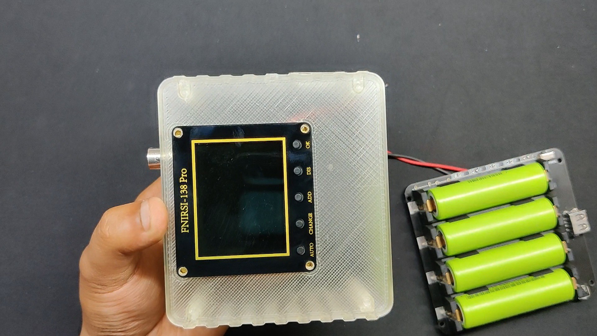
the Assembly is complete.
3
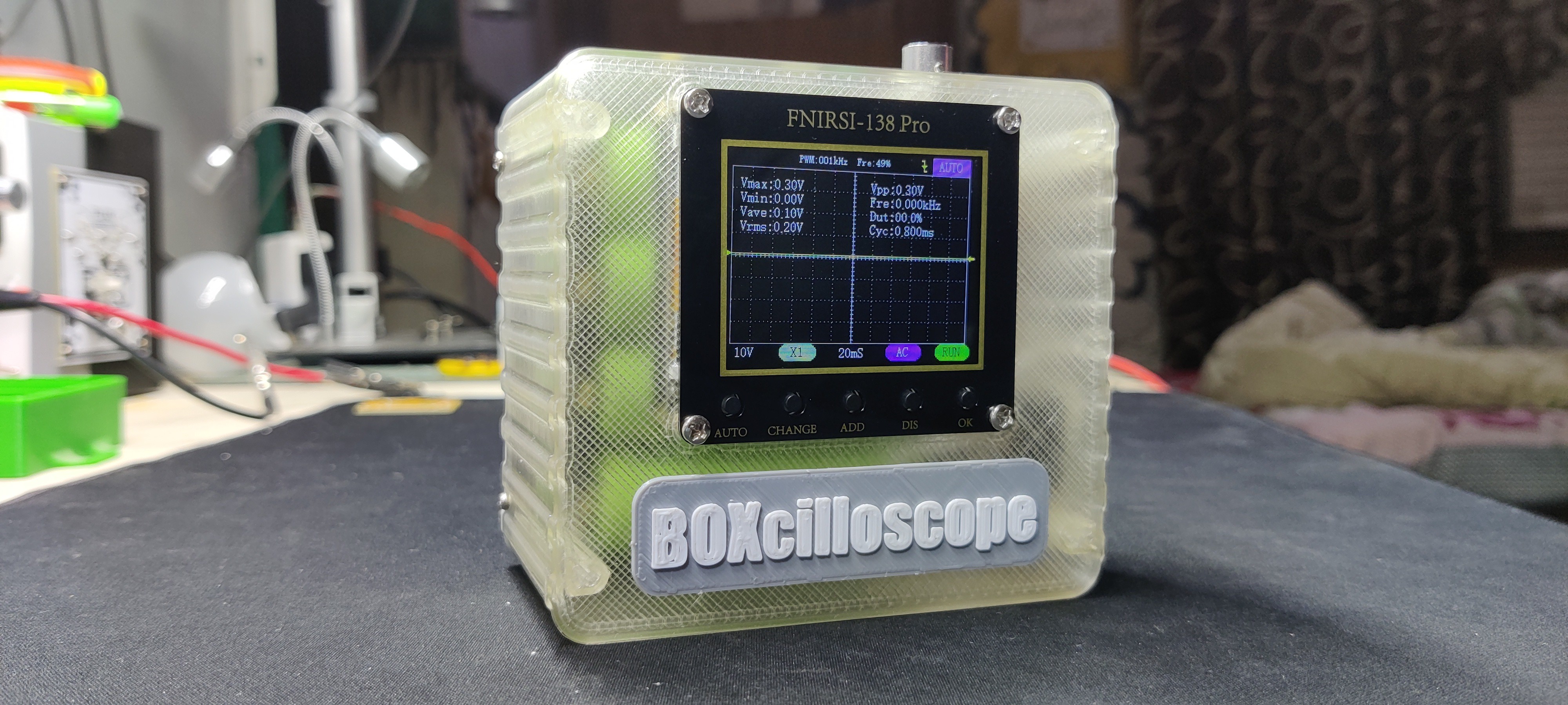
RESULT
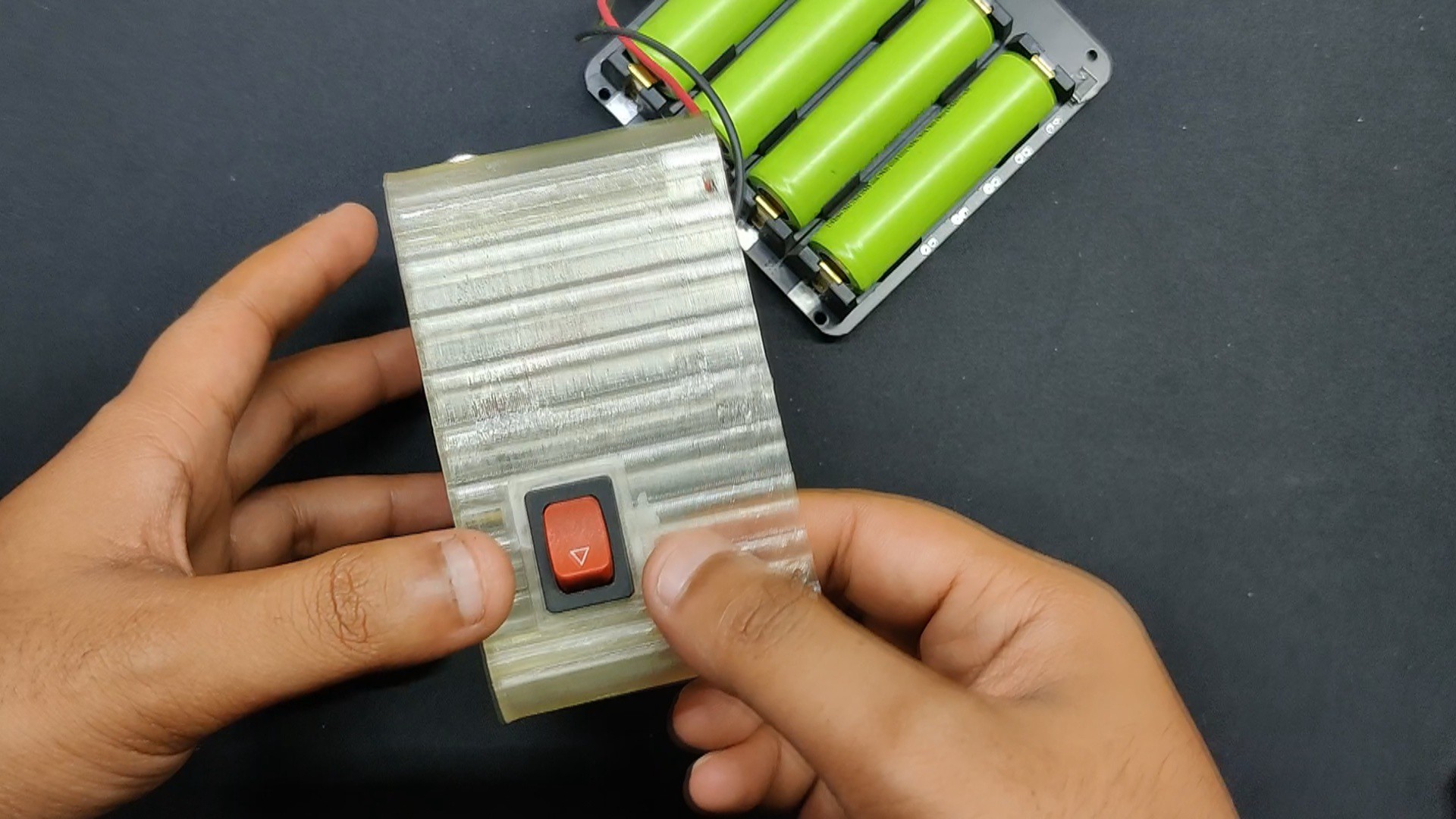
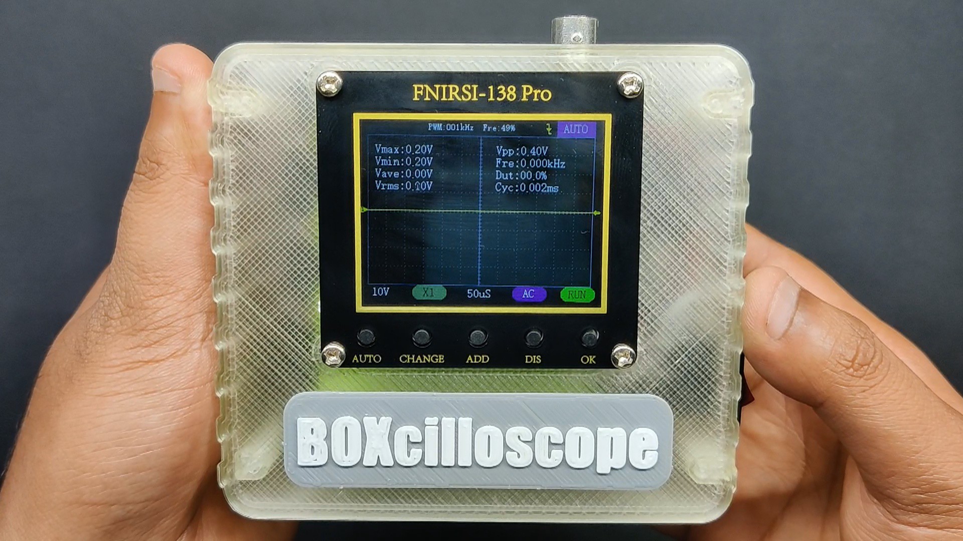
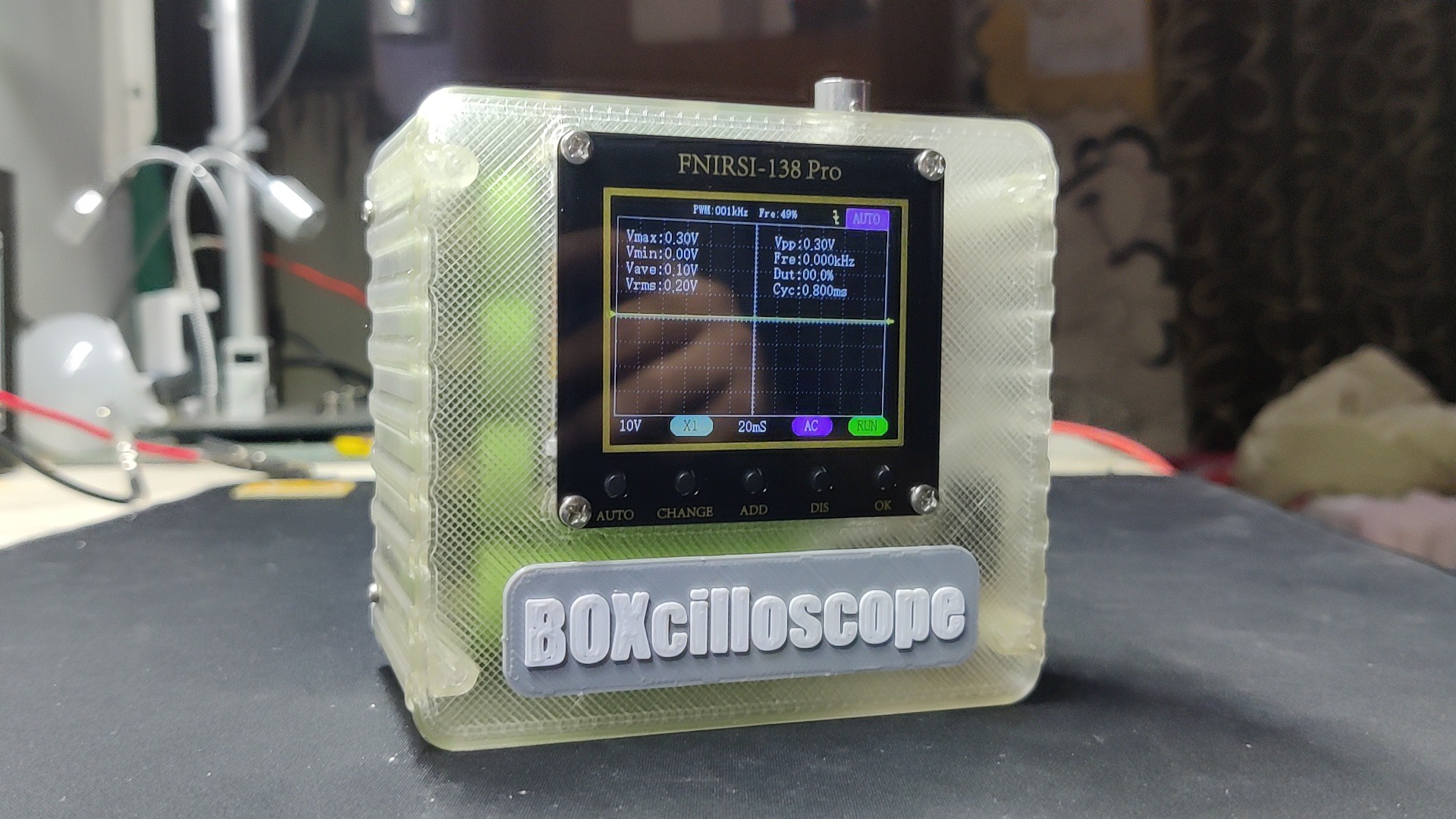
The result is a compact, portable, BOX-shaped oscilloscope with an inbuilt battery that we can use to examine any electronic component or device.
The device turns ON when the rocker switch is pressed for one second, and OFF when it is pressed for three seconds.
4
TESTING
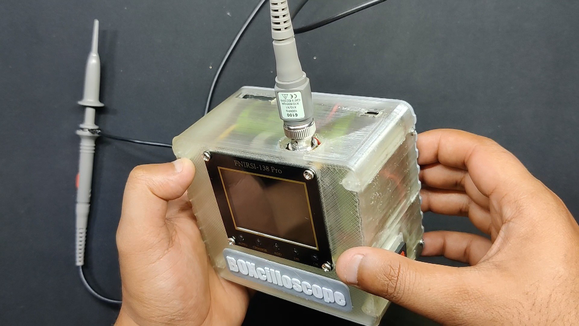
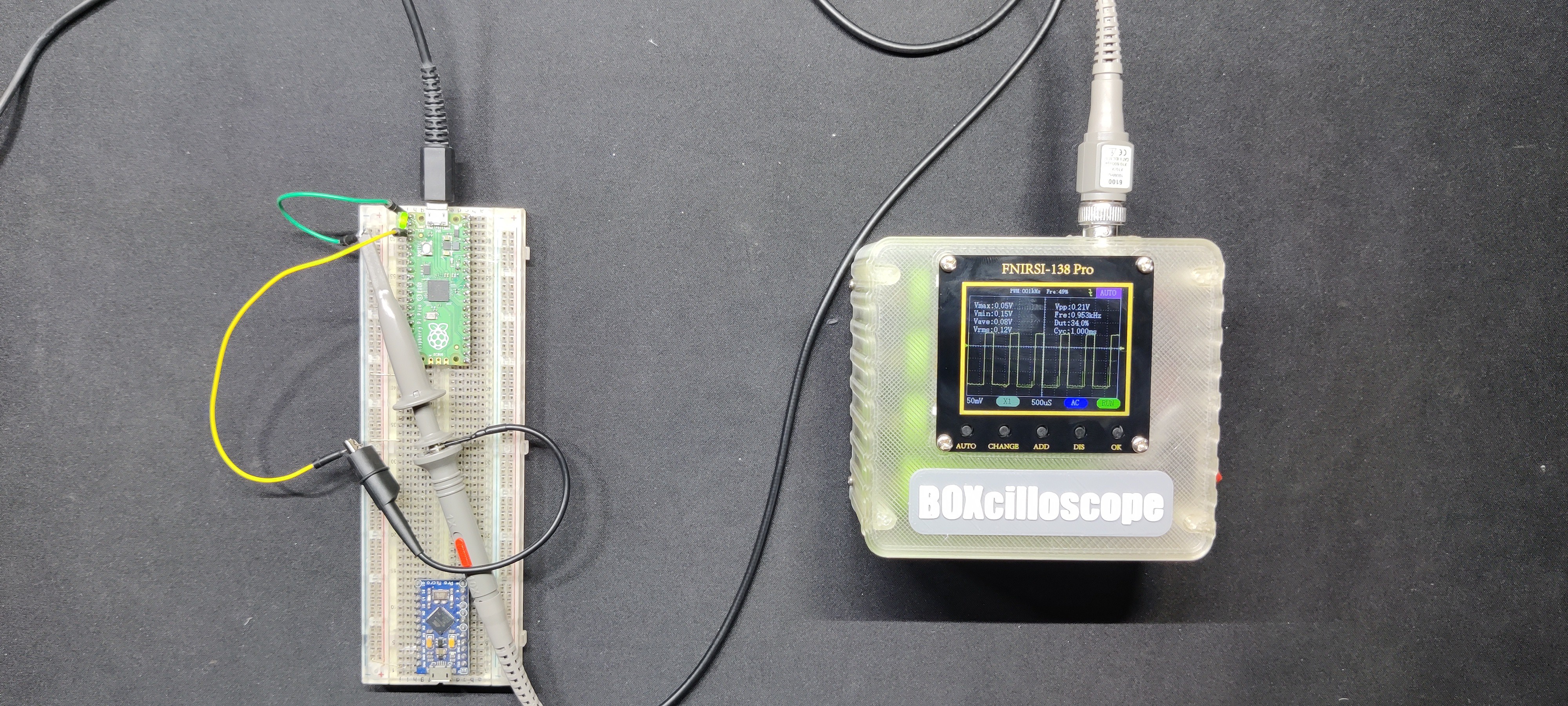
For testing the BOXcilloscope, we started out by connecting the 10X Probe to the Oscilloscope's BNC Port.
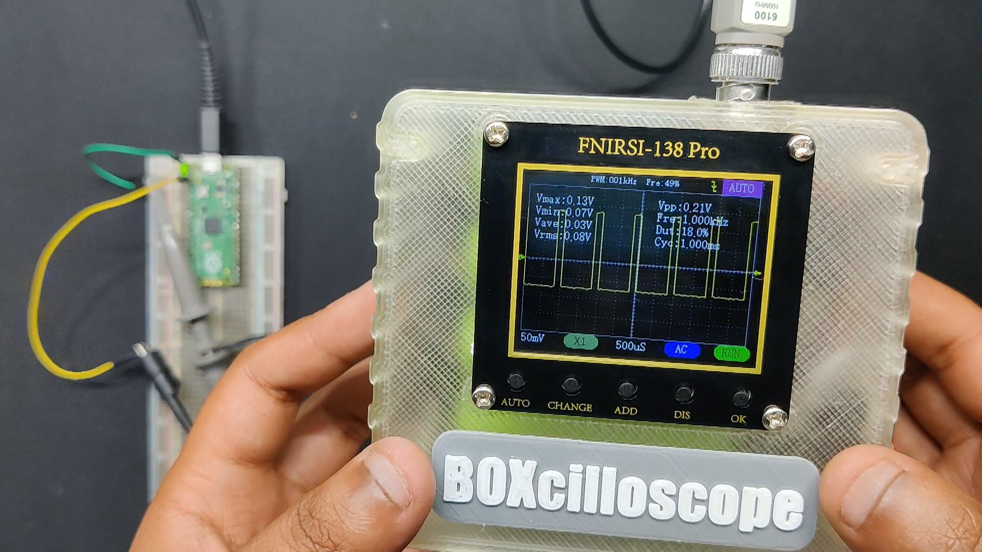
Next, we utilize a simple Raspberry Pi PICO setup with an LED connecting to GPIO0 and GND. In this setup, we connected the probe's negative lead to PICO's GND and its tip to GPIO0.
Here, we have added a FADE sketch into the PICO, In the Fade sketch LED brightness is gradually increase and decreased using Pulse Width Modulation.
The analogWrite() function sets the duty cycle of the PWM signal. A value of 0 corresponds to a 0% duty cycle (LED off), and a value of 255 corresponds to a 100% duty cycle (LED fully on).
We can see the duty cycle change in the BOXcilloscope, which ranges from 0% to 100%. This occurs at a linear pace and quite quickly.
The signal's wave shape is also being observed.
5
CONCLUSION
Although there are some lower frequency stability and accuracy errors, overall, this is a useful device that is best suited for beginners or hobbyists who want to start with electronics. The quality of the included 10X probe is not up to par with good 10X probes offered by brands like Tektronix or HANTEK. In addition, we notice increased phase noise, which can cause issues in delicate applications like communication systems.
Aside from the nitpicks, this is a helpful tool for beginners.
Overall, this project was a success and needs no further revisions.
 Arnov Sharma
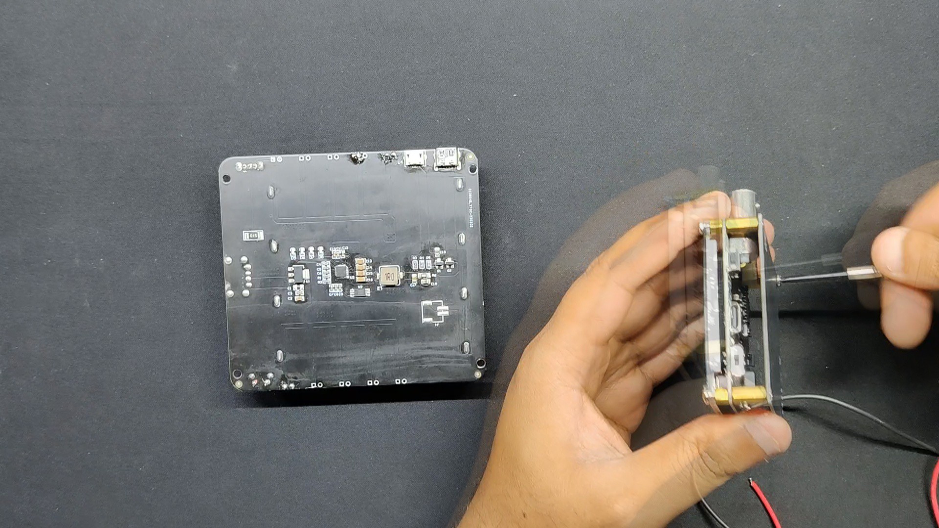


Discussions
Become a Hackaday.io Member
Create an account to leave a comment. Already have an account? Log In.