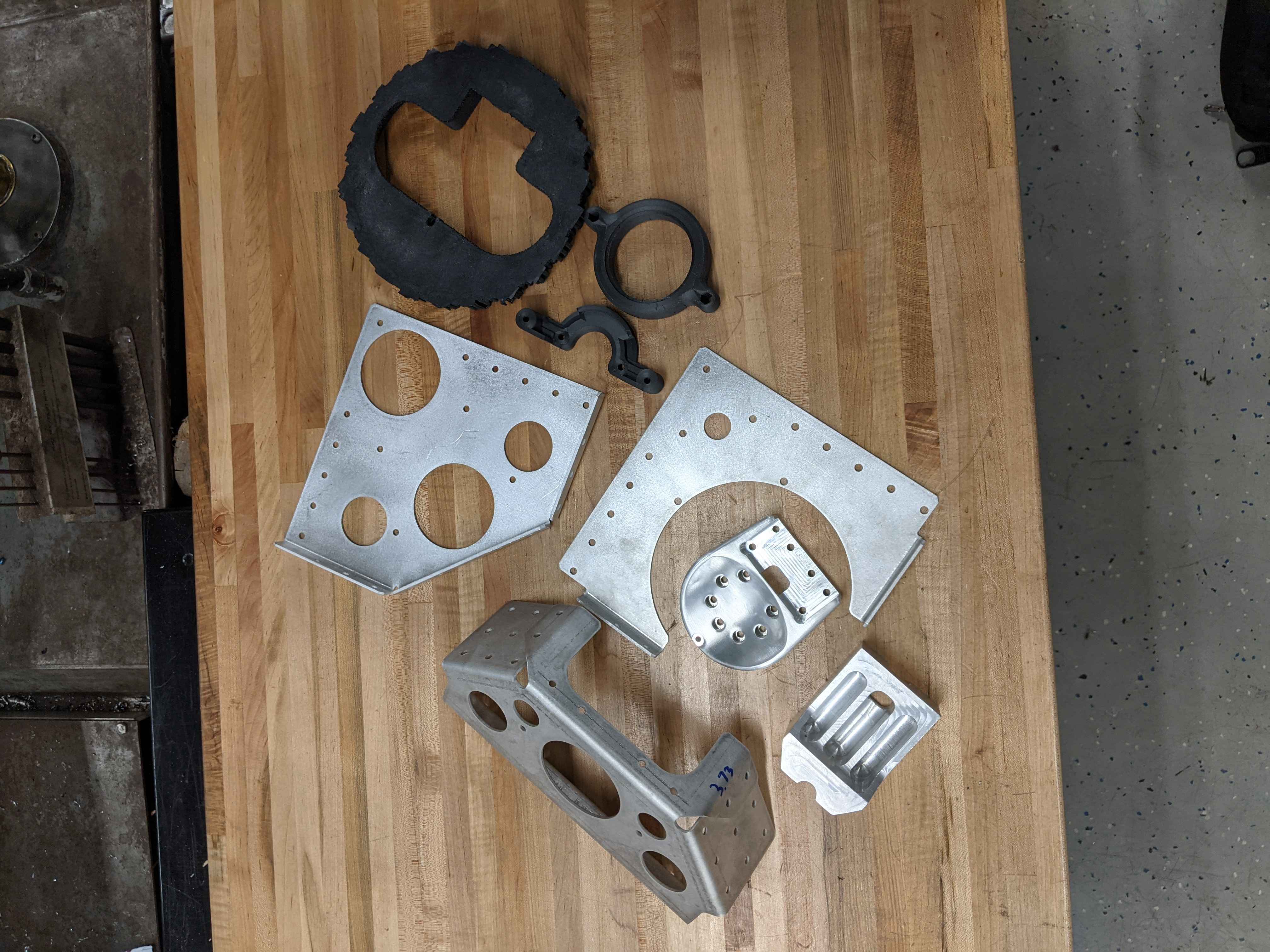
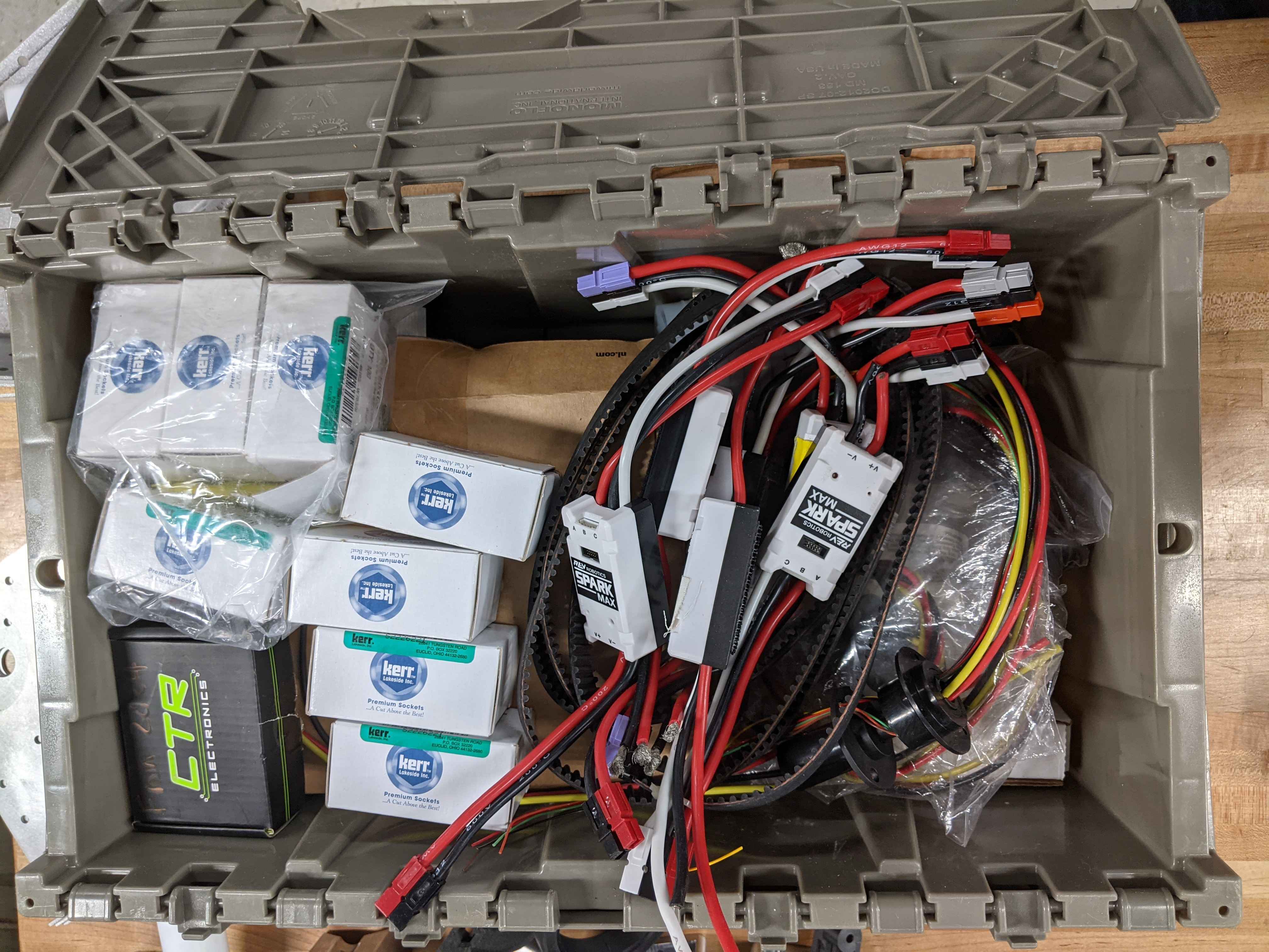
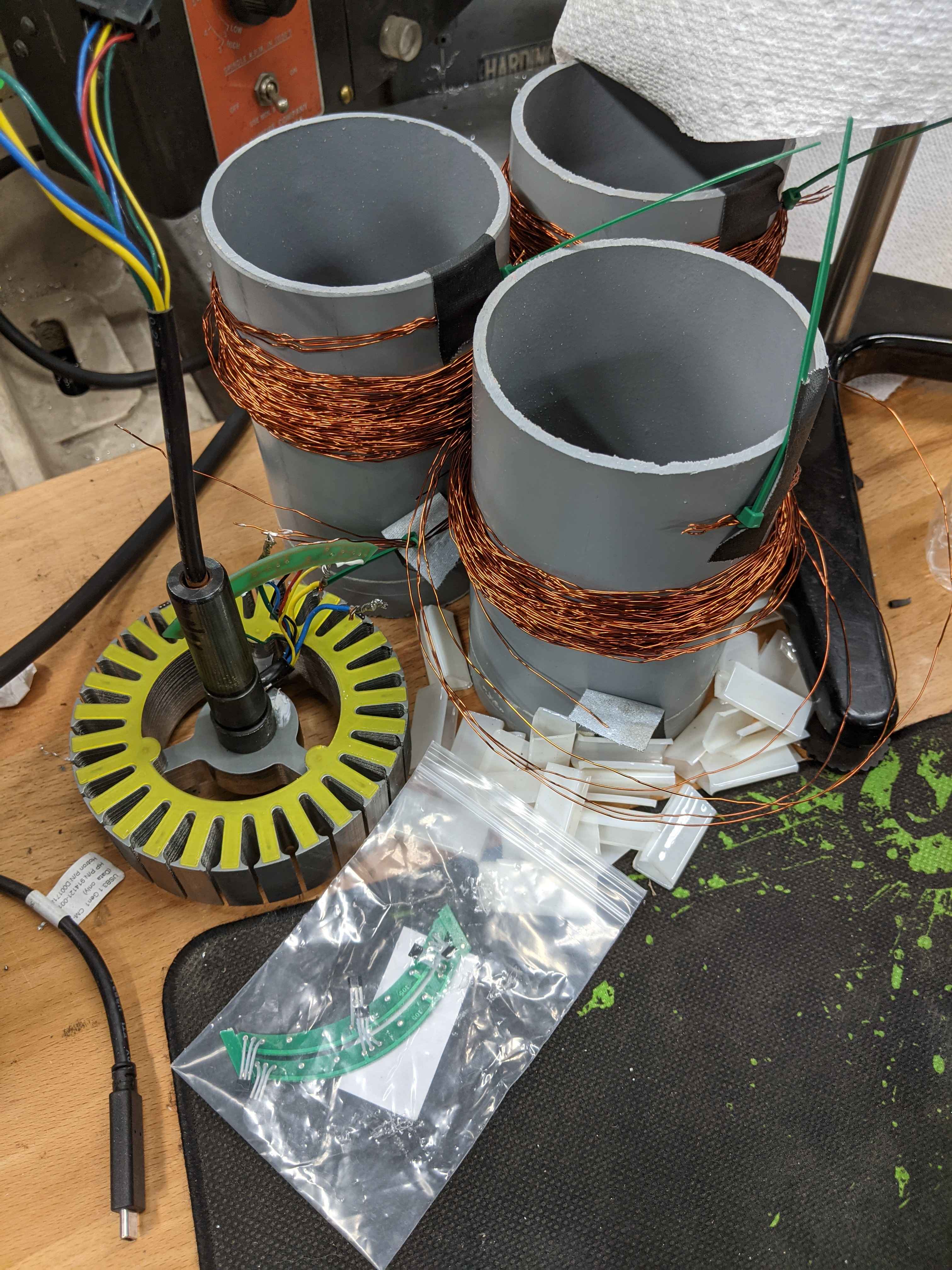
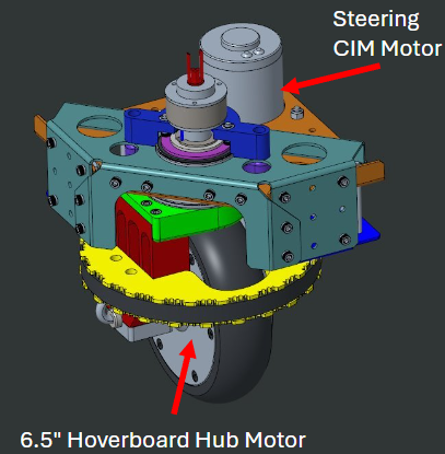
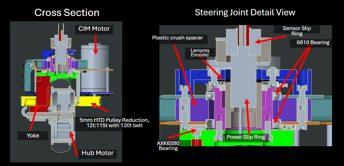
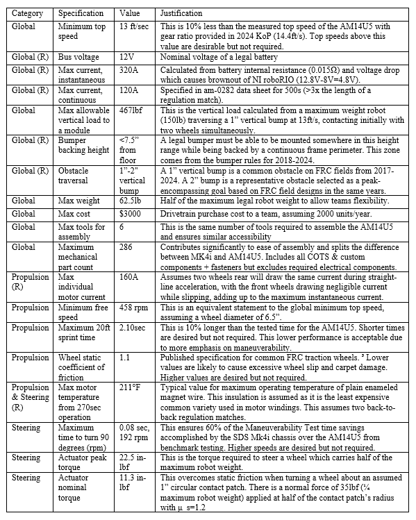
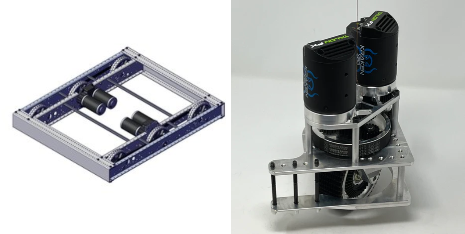
• Log #5 - Winter Break Progress and The Coming Semester

    THowden-Capstone16 hours ago 0 comments

    Current Status 

    As we begin the Spring 2025 semester, allow us to present team EverySwerve’s accomplishments over the winter break and the current tasks we are working on. 

    Tasks completed include:  

    • Custom components for a singular wheel module have been manufactured. Including 3D printed steering gear and CNC machined aluminum parts (Shown in Figure 1). 
    • COTS components have been bought and received for all wheel modules (Shown in Figure 2).
    Figure 1: Custom Manufactured Components
    Figure 2: COTS Donations

    Tasks currently under way: 

    • Software concepts have begun based on current CAD designs and future validation testing procedures. 
    • Hub motor rewinding is in progress to improve the performance of the drivetrain by altering the wye configuration to a slightly different wye config (Shown in Figure 3). 
    Figure 3: Motor Winding Progress

    The Coming Weeks 

    The team hopes to complete assembly of a single wheel module and begin the iterative software upload and validation process for it. This will allow us to ensure mechanical operation of a single wheel module before manufacturing all 4 units. As we begin the assembly process, we also plan to evaluate the most efficient building procedure, in order to create detailed assembly instructions. 

    As with all design projects, mechanical and software validation tend to create delays when things don’t work exactly as intended. Team EverySwerve is prepared for this possibility and has scheduled significant time to allow for iterative modification. We do not foresee any particular points of concern, but we are preparing for complications anyways. 

  • Log #4 - Final Design and Analysis

    THowden-Capstone11/19/2024 at 18:03 0 comments

    Summary of the EverySwerve Project 

    The EverySwerve project is being designed as a 1:1 replacement drivetrain for the FRC Kit of Parts. The goal is to design a high performing, swerve drive chassis with high maneuverability, easy assembly and lower cost. EverySwerve is comprised of four identical wheel module subassemblies held together by a frame of aluminum 1”x2” extrusions. Each wheel module has a hub motor for propulsion which simplifies power transfer through the steering joint(See Figures 1 & 2). A central hollow steering axis allows for a slip ring or wire bundle to pass through, eliminating the need for coaxial shafts and torque drive components used in popular COTS swerve modules. 

    Figure 1: Wheel Module Design Architecture
    Figure 2: Labeled Wheel Module Cutout

    Progress 

    In order to design an FRC-rules-compliant and efficient swerve drive module, Team EverySwerve conducted numerous types of analysis; including loaded stress analysis, bolt, bearing analysis, thermal analysis, and motor and timing belt analysis. This guided much of our material and architectural designs in creating our final blueprint. Some key aspects to highlight are: 

     - Our use of cold-formed aluminum parts which have high yield stress and bending resistance, while     maintaining ease of machinability 

     - Use of CNC manufactured components to prototype die-castings 

     - Determination of bolt preload values 

    Conclusion 

    From November 9th-23rd, Team EverySwerve has completed all the preliminary analysis for the EverySwerve module.  FEA stress analysis on billet and Sheetmetal components has been completed and modifications to hotspots have been taken care of.  Torque preloads have been determined for the bolted joints and simple thermal calculations proved that there is minimal concern with the heat generated by the motor within our design case(See Figure 3). 

    Prior to the start of the 2025 spring semester Team EverySwerve will begin procuring COTS components, manufacturing the custom components and generating the assembly instructions of the EverySwerve device. Beginning these tasks will permit us more time for building and validating the device later in the semester. Additionally, it will allow time for unforeseen issues with the assembly and performance of the device to be resolved. 

    Figure 3: Drivetrain Simulation Results

  • Log #3 - Project Progress and Path Forward

    THowden-Capstone11/10/2024 at 05:08 0 comments

             As we near the end of the semester, we would like to take stock of our progress and the path forward in completing the EverySwerve module. 

    Completed Work

             Major COTS component selection is complete, with motors, slip rings, and encoders. Initial CAD models of wheel module assemblies have been developed (See Figures 1 & 2), with finer details being reviewed for manufacturability and ease of assembly. Validation plans have been fully designed for use during semester 2, with software concepts being discussed and reviewed. A fully outlined table of constraints (Shown in Table 1), outlines the numerous parameters that must be taken into account as we continue development.

    Figure 1

    Figure 2

    Table 1

    Potential Obstacles

            Over the next two weeks, the team will be working heavily in FEA to simulate responses of joints under varying loads and conditions. Considering our lack of experience with programs like COMSOL and Abacus, one potential obstacle will be setting up accurate boundary conditions and test case conditions. We plan to overcome this with iterative review and using FEA as a guide to potential issues; not the definitive answer to our design validation.

    The Path Forward

            The team’s plan for the near-term work is to begin to set up strong CAD models for FEA analysis that can adapt as components experience changes and finalize vendor quotes and timelines. By November 23rd, the team hopes to be almost complete with all analysis of the device, ready to present for our Semester 1 design review. 

  • Log #2 - Outlining Constraints and Challenges of the EverySwerve Project

    THowden-Capstone09/24/2024 at 16:22 0 comments

    Constraints of the Project 

            As mentioned in our previous post, this project contains many constraints outlined by the FIRST Robotics Competition rulebook. These constraints define aspects of competition-ready robots, including weight, height, perimeter, electrical components and capabilities, and damage prevention. The constraints that will play an important part in our design of the EverySwerve module have been outlined below.   

    Table 1: FRC Constraints

    ConstraintValueSource
    Number of Propulsion Motors No more than 4 FRC Game Manual R502 
    Maximum Current 270A for 5 seconds 
    120A for 500 seconds
    MK ES17-12 data sheet  am-0282 data sheet 
    Maximum Weight No greater than 125 lbs. FRC Game Manual R103 
    Maximum Frame Perimeter No greater than 120 in. FRC Game Manual R101 
    Battery No more than 1 12V 18.4 Ah SLA Battery FRC Game Manual R601 
    Wire and Breaker Size 40A breaker, no smaller than 12 AWG Wire 
    30A breaker, no smaller than 14 AWG Wire  20A breaker, no smaller than 18 AWG Wire 
    FRC Game Manual R622 
    Field Damage Traction devices which damage the competition field are not allowed FRC Game Manual R201 and R202 

            One of the challenges of pursuing a cheaper, and higher performing KoP drivetrain is finding motors that are both FIRST compliant and perform at the desired level. With this in consideration, motors not currently approved may be required to achieve the goals of this design project. As most of the constraints provided by FRC are basic safety restrictions with avenues to get new components approved, we do not foresee this being a major issue. Another challenge arising from motor selection is the potential for high current, high weight options that cause our design to infringe on the set limitations. For this reason, we plan to heavily analyze every motor we consider to ensure it aligns with our constraints.


    Benchmarking Current Solutions

            To understand the key physical challenges in the design of EverySwerve, benchmarking of existing solutions must take place. The benchmarking of the two existing drivetrains will provide many key performance metrics that will inform decisions when selecting components for the design. To facilitate the selection of COTS components, reference design parameters will be selected based on calculations of the required physical parameters and use of component data sheets.   For motor selection, calculations will determine a torque generated based on the physical parameters of the motor. For a single phase in a brushless DC motor, the static torque is described by:

    Where N is the number of turns in a motor winding, B is the magnetic flux density (a known value common to magnets used in inexpensive brushless DC motors), Y is the length of the stator, i is the current through the phase winding (for which a limit is defined by constraints), and D is the diameter of the stator. The desired torque value will be determined by comparison to the benchmark drivetrains as well as a desired acceleration of a complete drivetrain (F = m*a, τ = I*α) to meet benchmark test values. The values of N, Y, and D will be iterated upon to determine approximate motor parameters, which will be used in the search for an appropriate COTS motor. Some COTS motor suppliers will specify these physical parameters or provide motor curves which display the performance characteristics, but many will supply very limited data. In the design team’s experience in procuring COTS motors, inexpensive options are often marketed as for a specific application; i.e. “electric scooter motor” with only a specified voltage, top speed, and current draw. Since a major goal of the design team is to keep the cost low, products that do not have precisely specified performance...

    Read more »

  • Log #1 - Defining the Project

    THowden-Capstone09/06/2024 at 20:52 0 comments

            The FIRST Robotics Competition is a high school engineering program that utilizes both commercial off the shelf (COTS) components and custom components designed and manufactured by students. The Kit of Parts (KoP) is provided to all teams as a starting point for their design as a part of their seasonal registration fee. Built off a simple skid steer drivetrain that was originally designed nearly 20 years ago, the KoP (shown below) lacks the maneuverability that has become the competitive standard. Off-the-shelf “swerve modules” allow for rapid omnidirectional movement but are expensive and difficult to assemble, calibrate, program, and maintain. This makes it unattainable for many underprivileged teams with less funding, fewer mentors, or time to build, program, and test their robots. The COTS swerve modules (shown below) that are currently on the market are too expensive and complex to be scaled up to inclusion in the KoP. 

    Figure 1: Current Kop AM14U5 Drivetrain vs Expensive COTS Swerve Module

            Our goal is to solve this problem by proposing a new KoP drivetrain, focused on a new “swerve module” design, allowing for the speed and maneuverability available to top teams. Some constraints come from the current FIRST rules set for robot construction, like electrical specifications: 12V 18Ah SLA battery with a peak current draw limit, REV Robotics Power Distribution Hub with 40A breakers, and a required NI roboRIO robot controller with a specified baud rate and communication protocol.   In order to meet the design objective, the purchase cost should be roughly equivalent to the current KoP drivetrain (~$1000), but at least significantly lower in cost than COTS swerve drivetrains (~$2500). A solution to this problem requires a detailed BOM outlining the cost as well as assembly steps that allow students to build and operate their drivetrain with comparable resources and time as the current KoP drivetrain (approximately one full day with a few students). These will be included as deliverables along with a functional physical prototype drivetrain and sample control code. The focus has been set on the Swerve Module as making swerve accessible to all teams in the program will raise the floor and enable all teams to have a better experience when competing. 

            During the time that we spend coming up with solutions to the problem, we expect some obstacles, including selecting appropriate motors and minimizing the volume that the module takes up. Most problems that we encounter will be solved through iterative design. Benchmarking the current options available, including the current KoP drivetrain as well as the most common COTS Swerve drive train, will be critical in helping define the problem as these benchmarks will inform the specifications for the solution.