Check out the YouTube video for more details:
What is it?
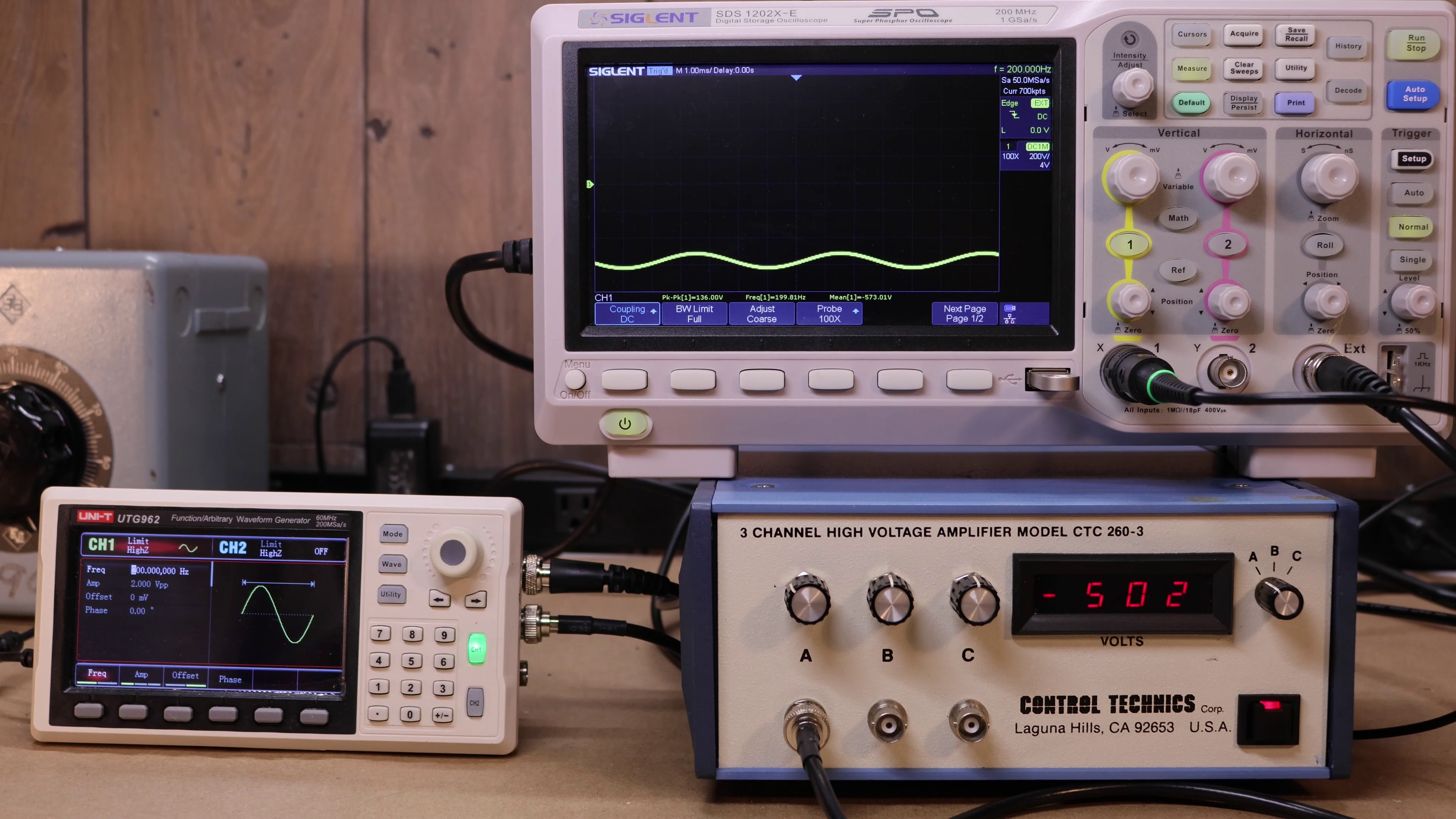
Turns out this is a high output impedance DC to 1.5Khz amplifier. I'm not an expert on when you might need something like this, but one use case I could imagine is testing ceramic capacitors DC bias capacitance change with voltage.
If you have other ideas please let me know! Below are some pictures, and test results.

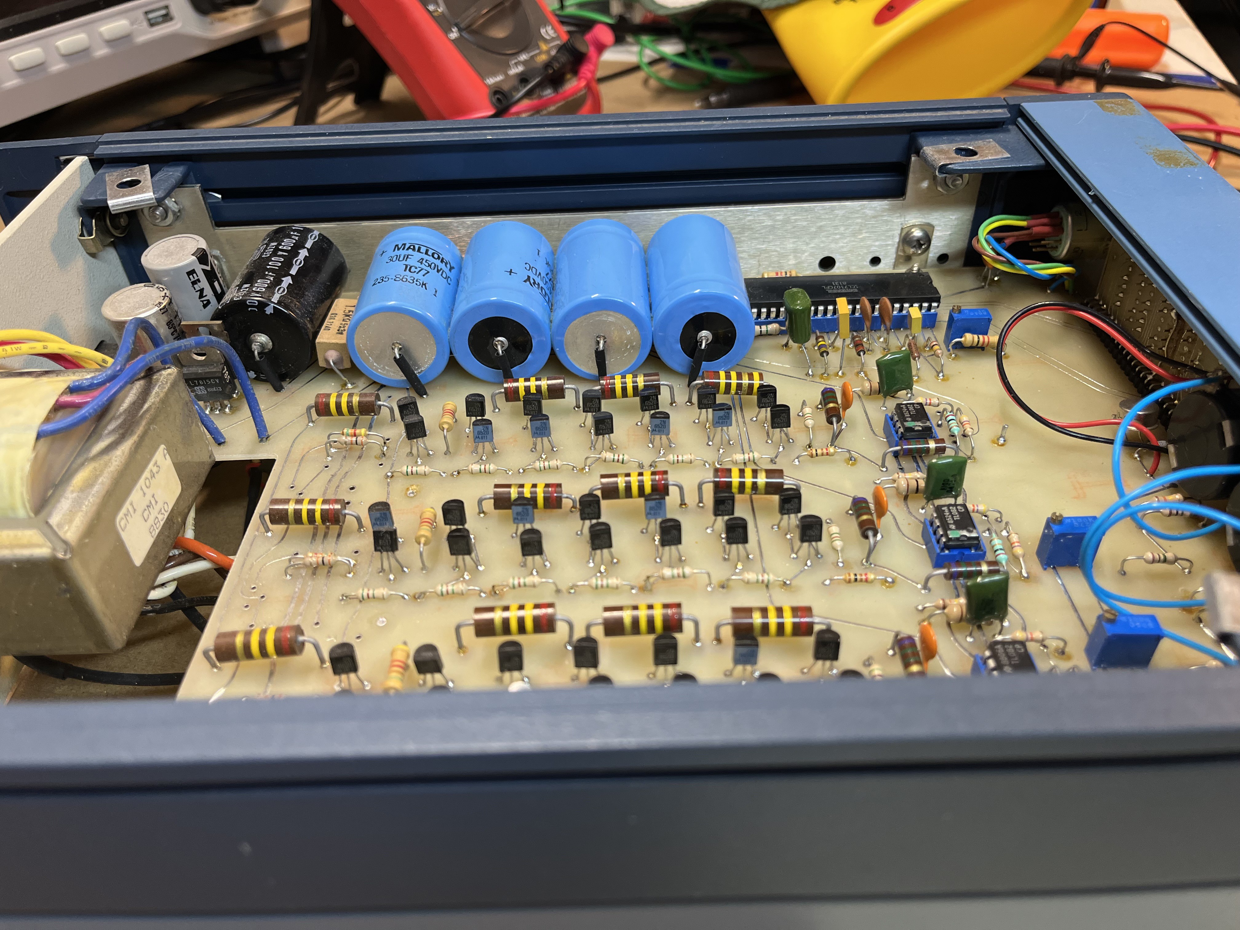
Inside Peek:

Approximate Specification:
Based on measurements I produced a rough set of specifications below.
| Specification | Min | Max |
| DC Voltage | 0 | -1000 |
| AC Frequency -3dB | DC | 1.5kHz |
| AC Signal Gain | ~40 v/v | N/A |
| Output Resistance (AC) | 780k Ohm | N/A |
| Output Resistance (DC) | 1030k Ohm | N/A |
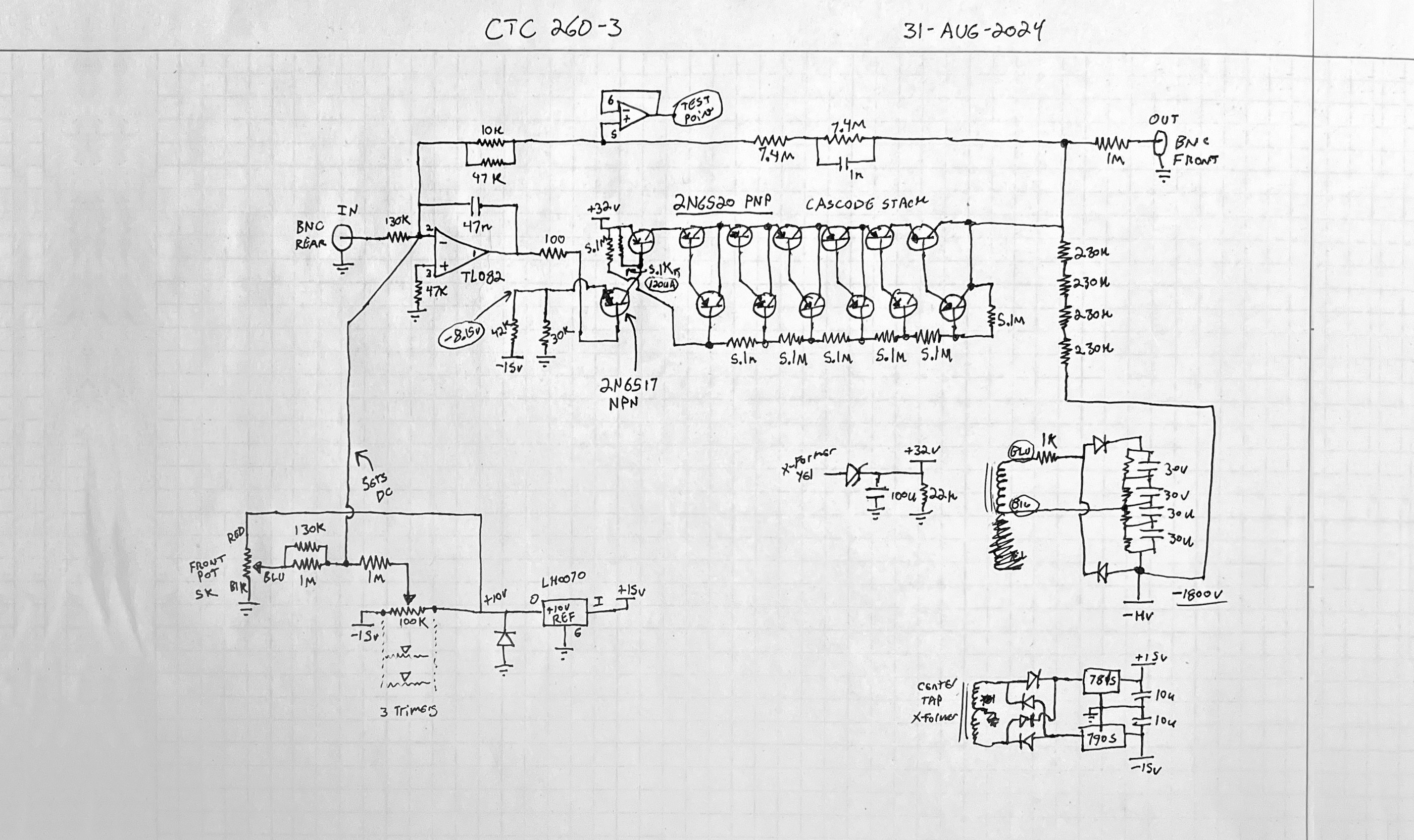
Schematic
Below is a simplified schematic based on the major components on the board. The power supplies are simplified, but the critical AC/DC components are presented well enough to produce a simulation that matched the lab data collected.

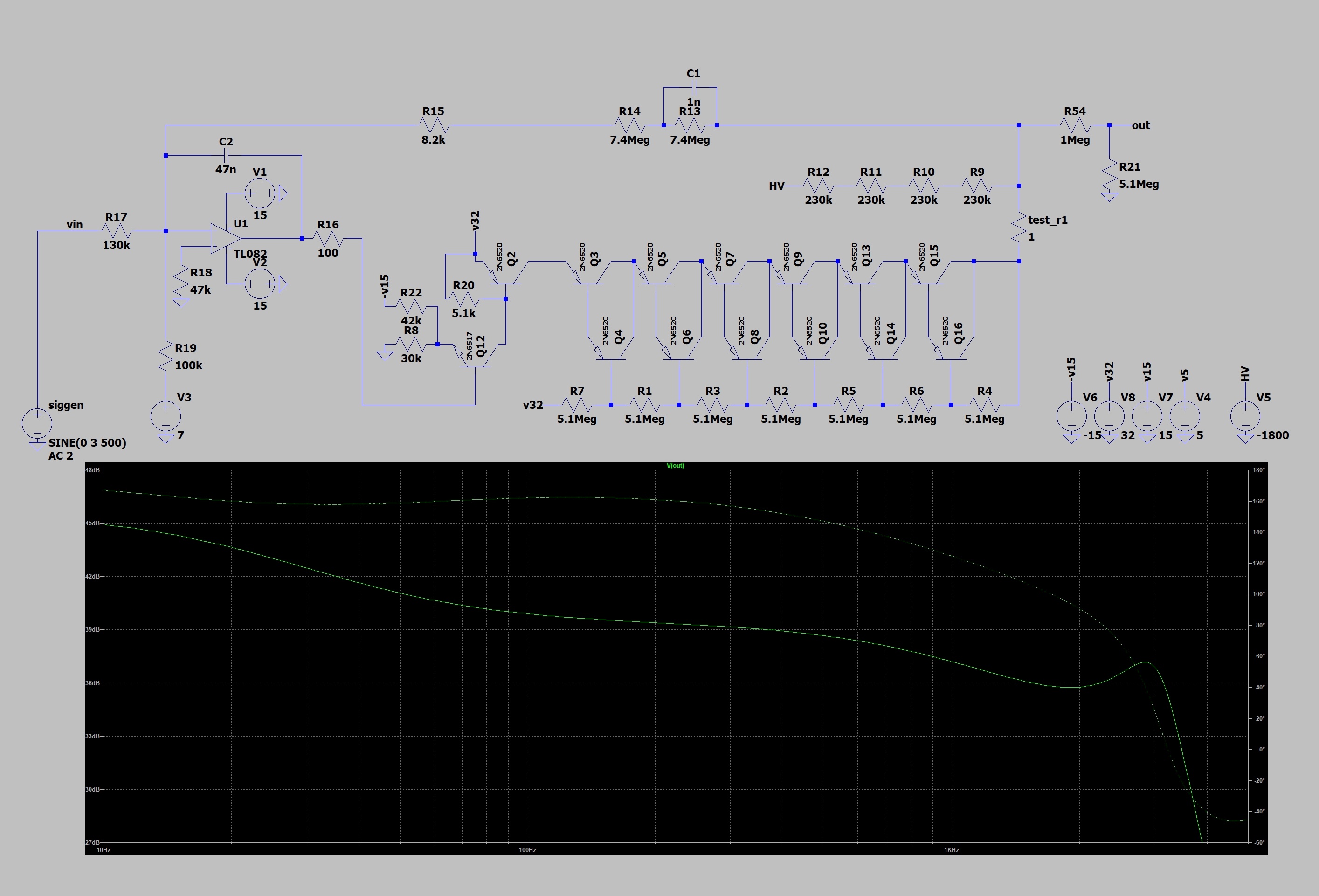
Simulation
Using LTSpice, The circuit was simulated. The frequency response was close the the measured value, so it appears the schematic is close to accurate.

 Collin Matthews