 deʃhipu
So, the first prototype PCBs arrived today, and of course there is a problem with them. But we will get to that. I only have one 0.66" OLED at hand right now, so I only assembled one badge, but it should be enough to test. Initially I planned to use the Vectorscope badge for testing, because it's the only Hackaday badge that doesn't have some weird PIC or FPGA brain, so should be easy to program to get the display running. Unfortunately, I underestimated Hackaday. The SAO connector on that badge has the pull-ups for SDA and SCL connected to the 3V3 pin of the pi pico, as it should, but the VCC pin is connected only directly to the plus terminal of the battery, bypassing even the power switch. This means not only that the SAO will not work without battery (and that with battery it will always work until it drains it completely), but also that if you connect it to USB without a battery, you are pretty likely to burn the I2C part, because it will get power on the pins without power on the VCC. Even with battery, when you connect it to USB, the pins will receive 3.3V from the pull-ups, but the VCC pin will only be the 3V or less of the battery, which is not something those delicate OLED chips are designed for. So I only connected the SAO to the unpowered badge to show how it could look like before being fried, and did all the rest of the testing by connecting jumper wires to the SAO connector.
I had a Xiao RP2040 at hand that even already had code for that particular display, because of the "eye" shield I made for #Wee Bug previously. A few female-to-female jumper wires, and I should have a working display. Unfortunately, all I got was the CircuitPython error message: RuntimeError: No pull up found on SDA or SCL; check your wiring.
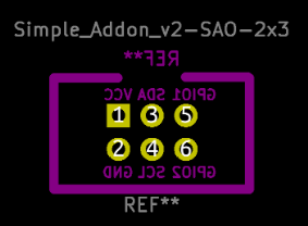
Hmm, so what's wrong with the wiring? I looked at the schematic, and I saw the problem. You see, the SAO connector specification shows this image:
So it wasn't suspicious to me that my connector on the schematic was connected like this:
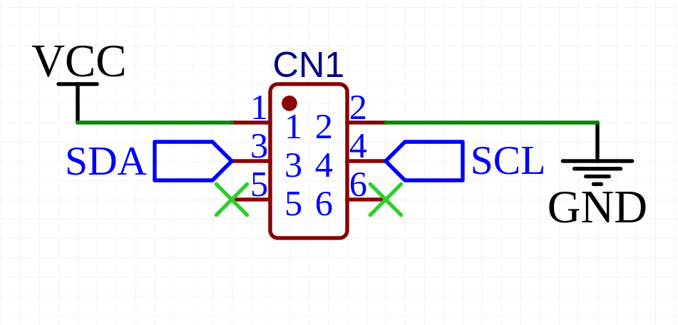
But that, of course, is wrong. I also didn't immediately notice this on the PCB view, because the connector was on the bottom layer, so the view was mirrored by default.
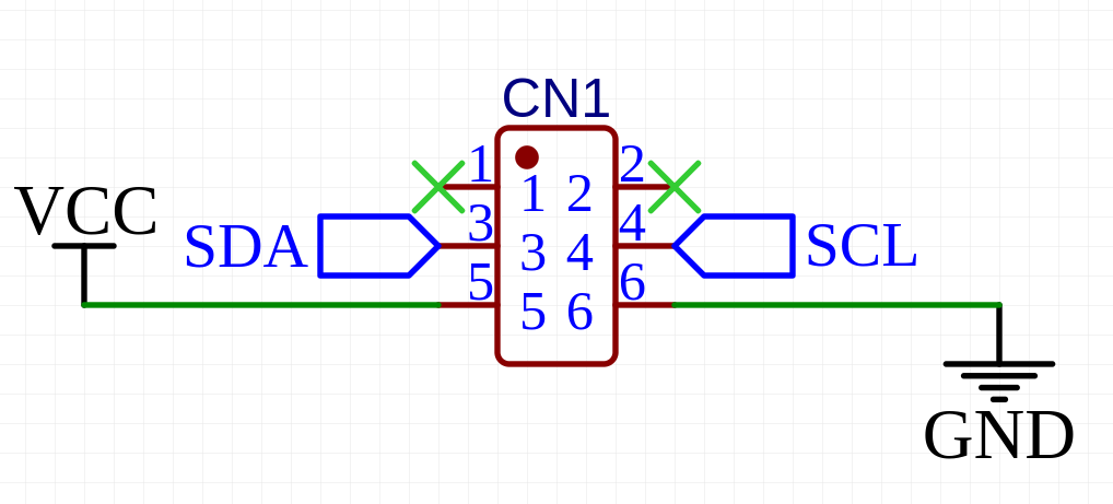
Of course the SAO connector specification lies. The correct connections look like this:
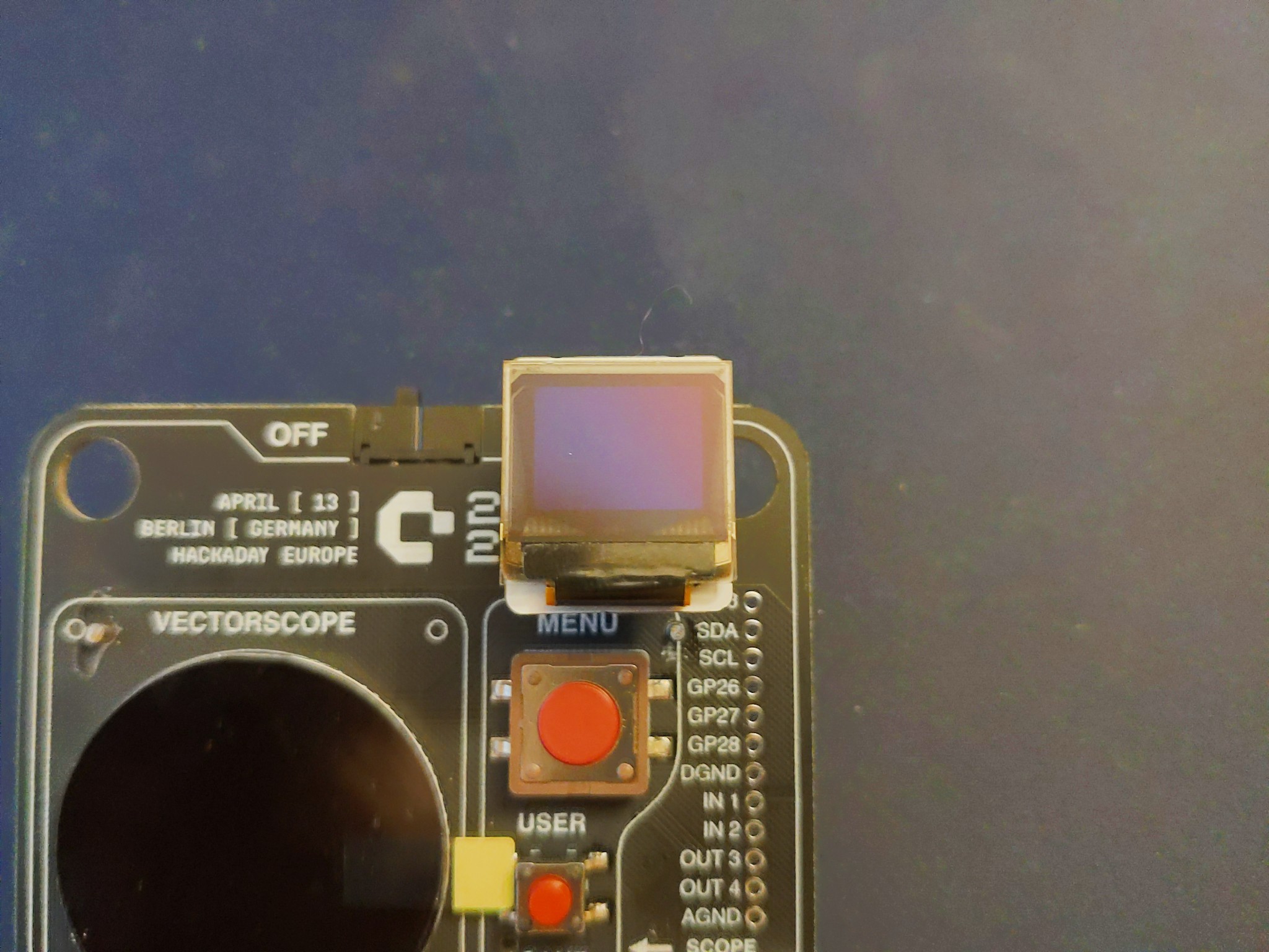
I fixed that on the schematic and on the PCB, and I will order the fixed boards with the next order. In the mean time, to test the rest of the SAO, I simply connected the power wires to the two pins on the other side, and voila:

We have the display working.
So when the new PCBs arrive, I will just move all the components to them, and it should be working.
Discussions
Become a Hackaday.io Member
Create an account to leave a comment. Already have an account? Log In.
I did the same thing on my project this year. And the Digikey SAO that came with the badge last year also has this problem. Maybe it's a rite of passage?
Are you sure? yes | no
The connection in the standard is correct, but the footprint is shown mirrored, because it's on the back of the board. You're definitely not the first to misinterpret that
Are you sure? yes | no