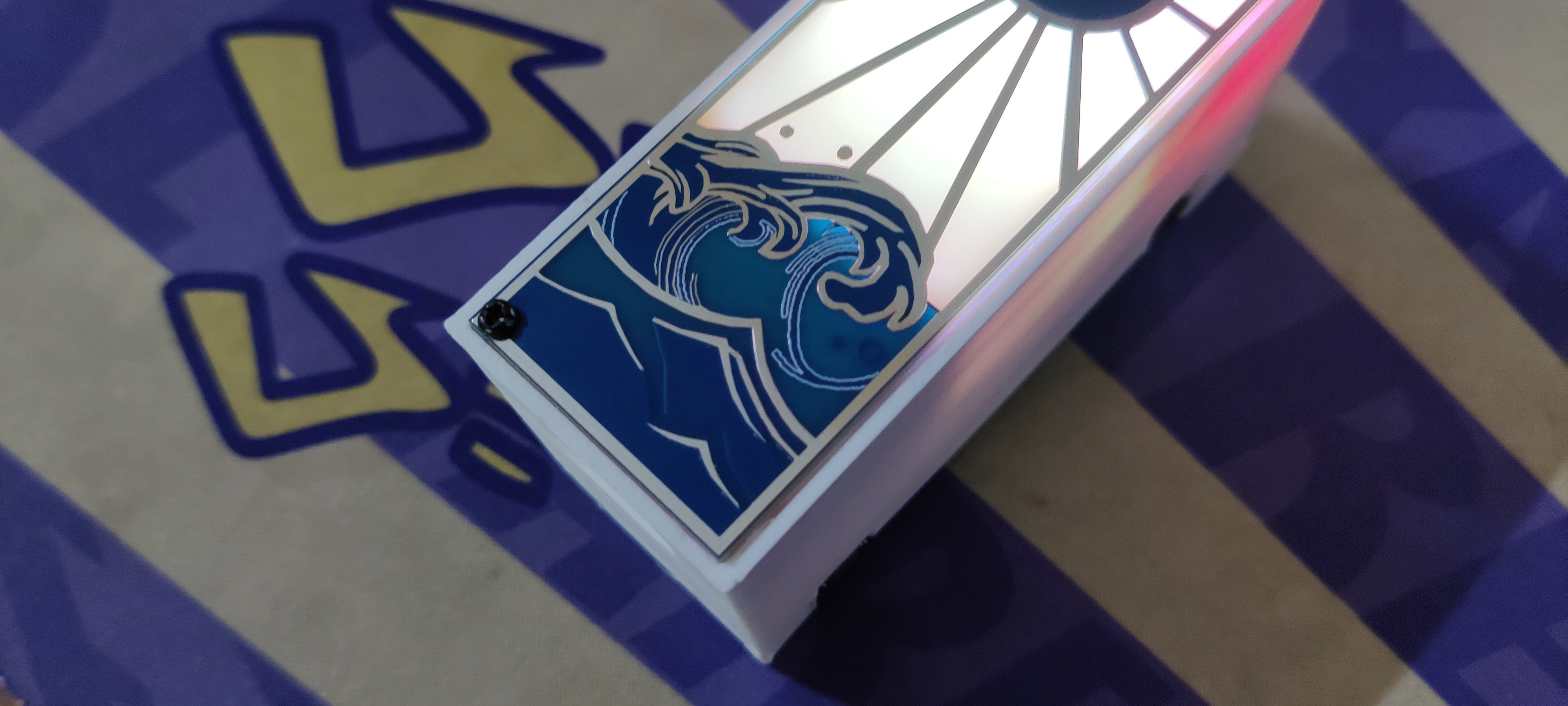
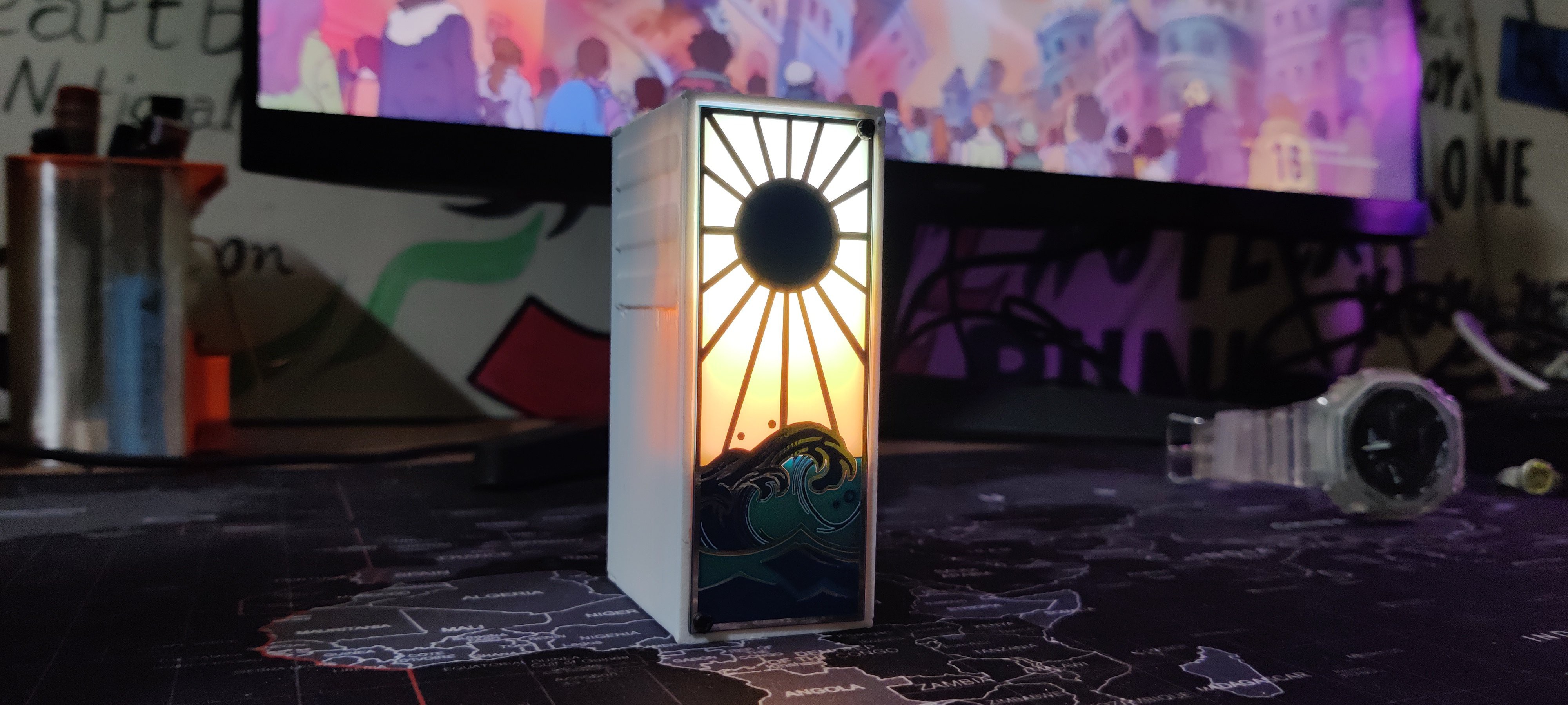
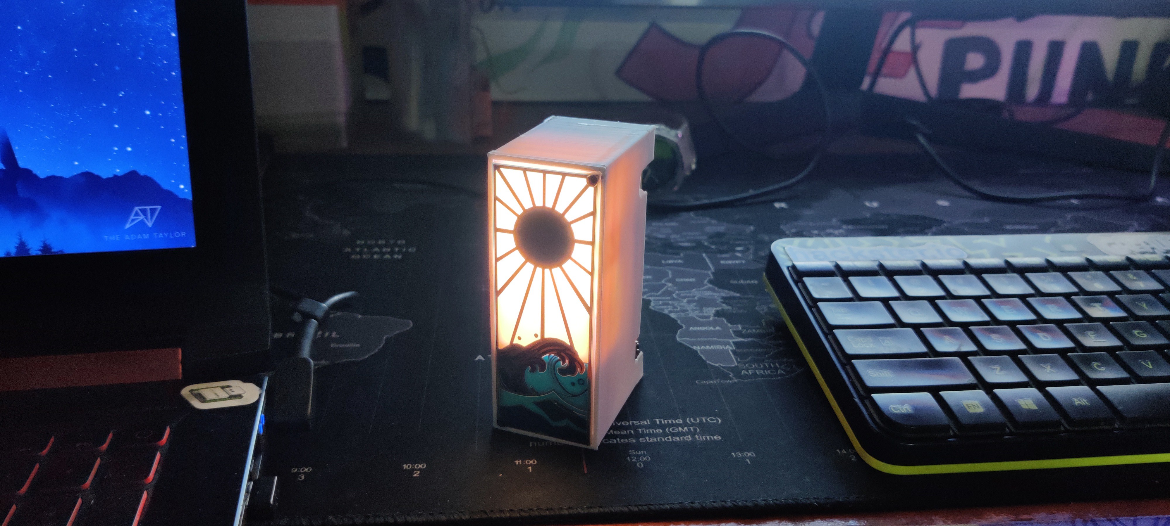
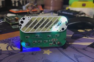
This gadget, which resembles a BOX, contains the lighting element, which is an XIAO RGB matrix connected to an XIAO SAMD21 microcontroller board. We have added a battery board PCB to the device's backside. It has an IP5306 Power Management IC, that raises a Li-ion cell's 3.7V to a steady 5V 2A, which powers the RGB LEDs and XIAO.
DESIGN
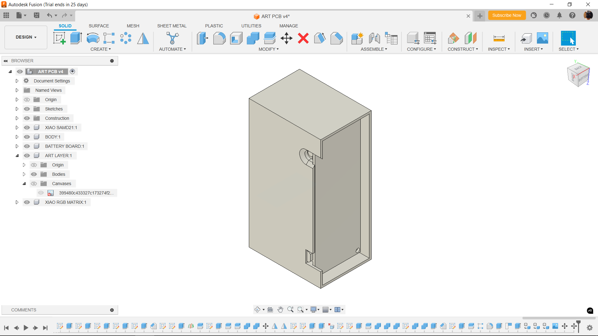
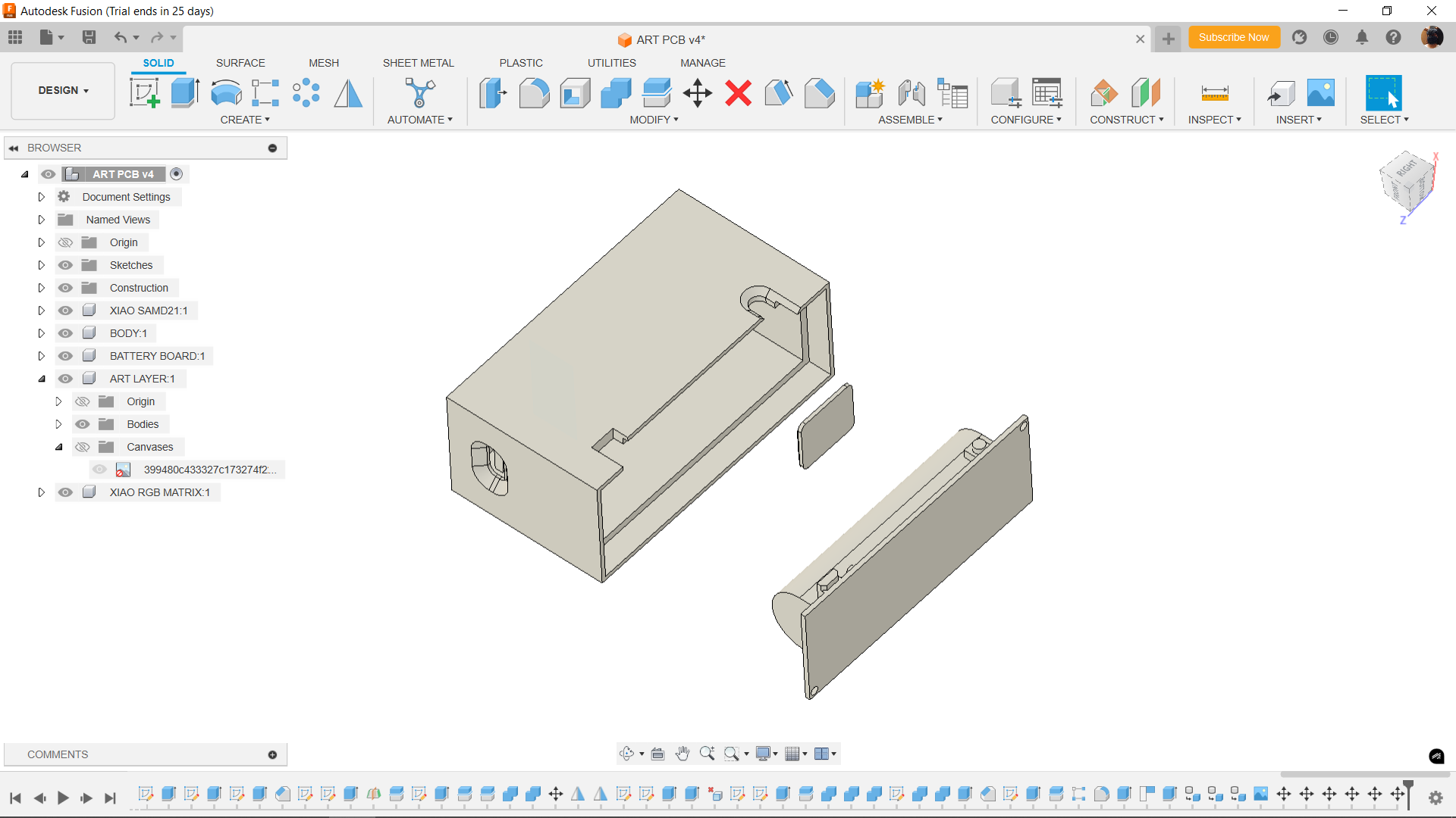

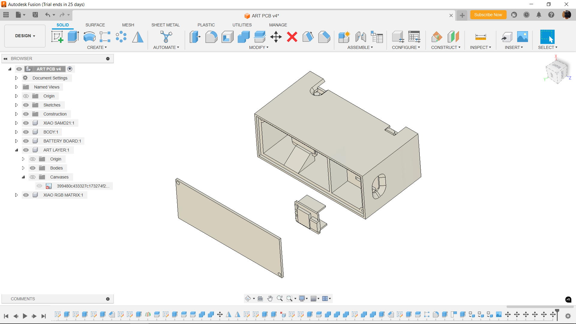


The design process began with Fusion360.
Here, we modeled the PCB that is positioned on the front and the identical layout that is positioned on the back; the only distinction is that the rear PCB has a lithium cell holder in addition to certain SMD and THT components, such as an LED, USB port, indicator, and IC.
After that, the two PCBs are joined with the help of a rectangular box-shaped part, in the center of which is the XIAO RGB MATRIX and SAMD21 microcontroller.
The idea here was that we have placed the XIAO RGB MATRIX in the topmost region of the design. We will be adding a solder mask opening in the PCB, which will allow the RGB light to see through only in the topmost region.
The Design was finalized and then 3D printed using white PLA with 0.4mm Nozzle and 0.2mm Layer height, infill 10%.
PCB DESIGN: THE ART LAYER

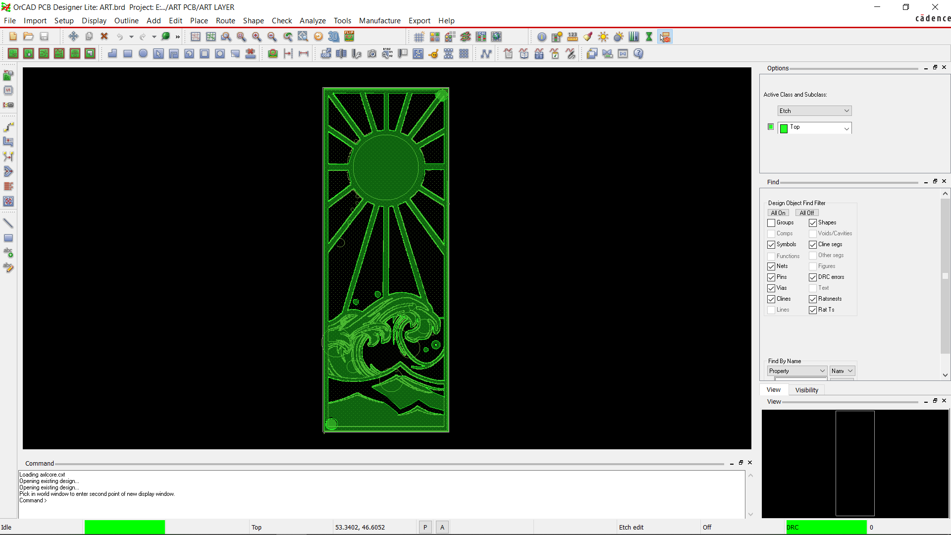
Finding an appropriate Great Wave off Kanagawa image was the first step in the PCB design process. We then imported the image into Inkscape and put a circular sun on top of the wave along a few lines that extended in all directions, representing sunrays.
Next, the entire drawing is crammed within a rectangular frame.
The dimensions extracted from the Fusion360 model were used to create the board's outline and include two mounting holes.
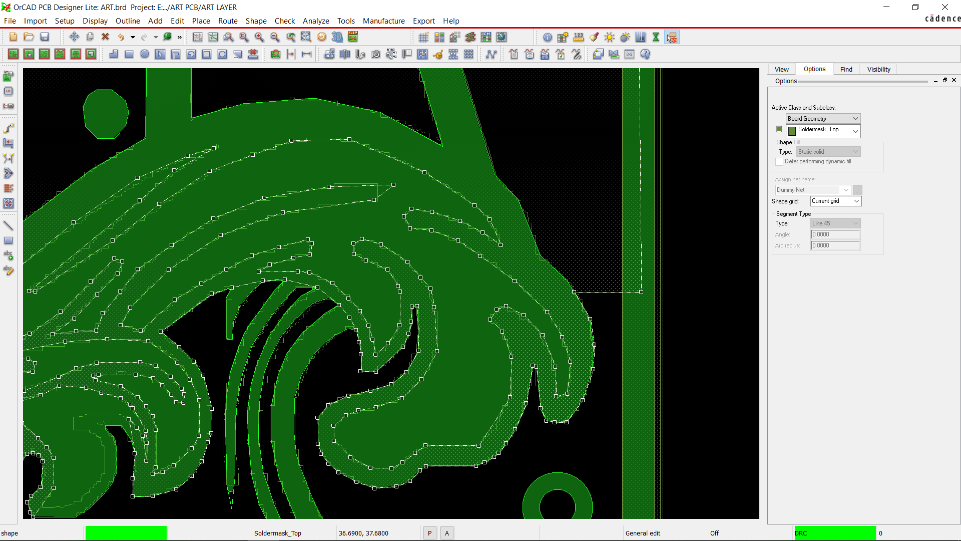
Here, we want to put etch where all of the black lines are, then open the etch to turn all of the black borders on the PCB into silver.
Additionally, we remove the solder mask from the top section between the sun's rays and the bottom section's solder mask to let light through the top portion of the board.
Since there are no electronic components on this board, we created the design in PCB Cad without the need for a schematic and exported the Gerber data after the design was complete.
PCB DESIGN: BATTERY BOARD
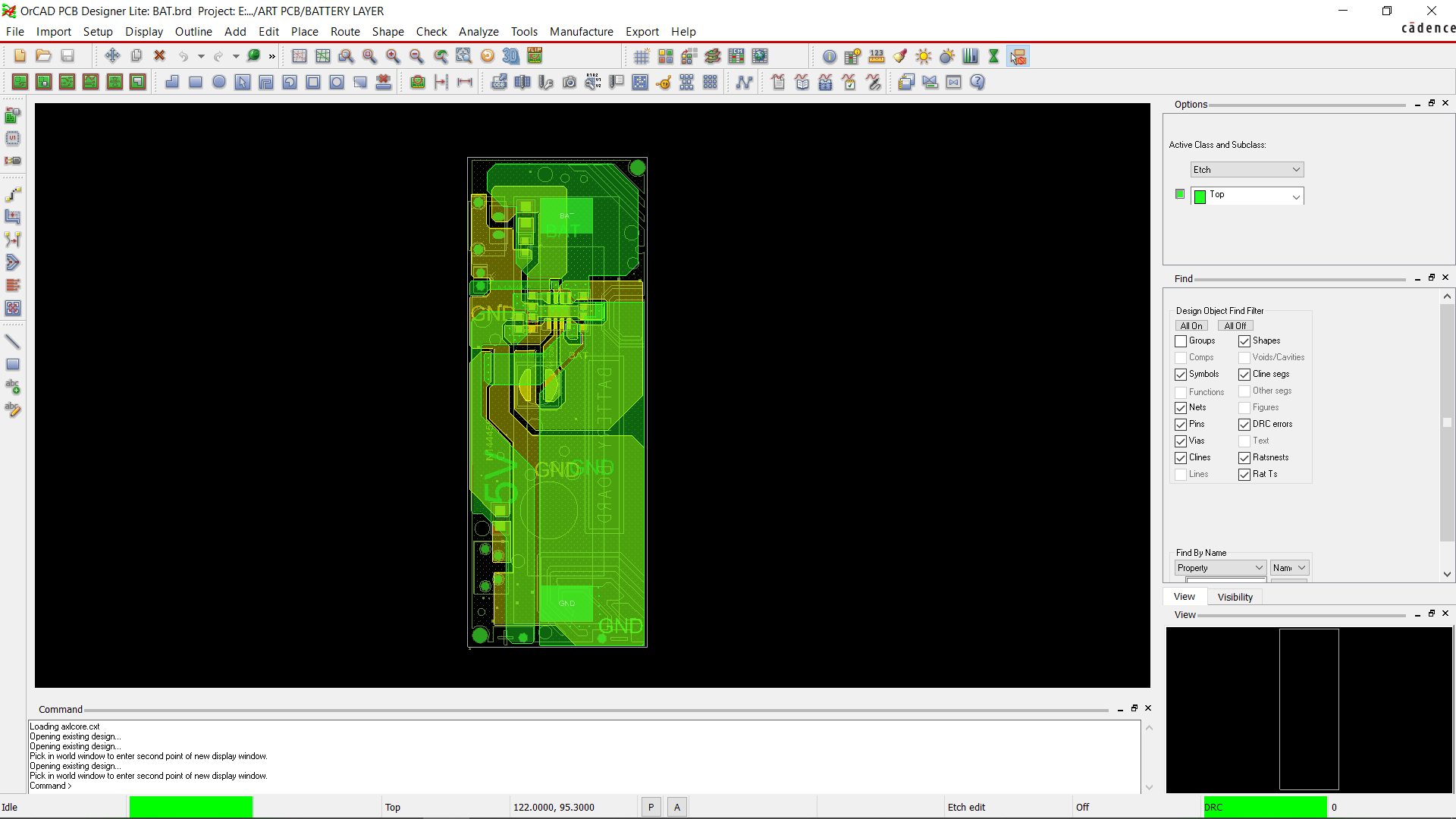
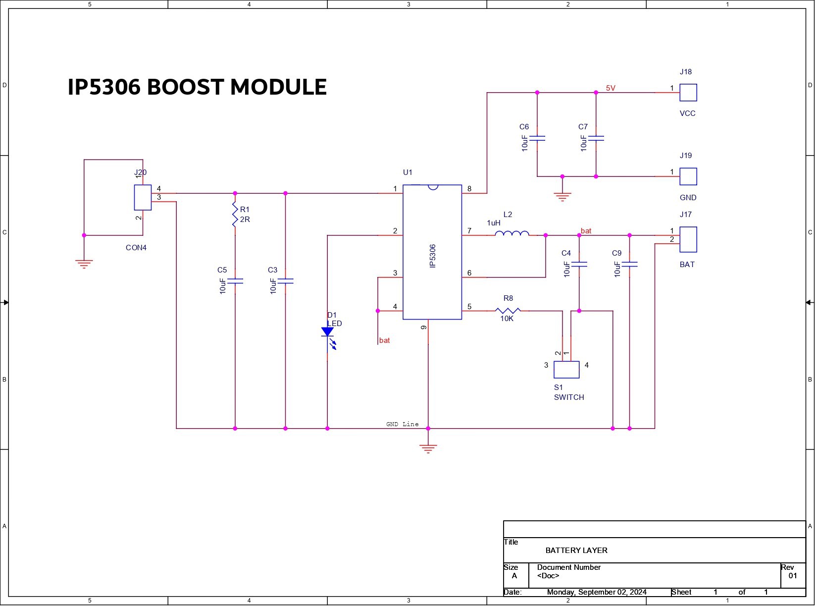
The battery board, which consists of an IP5306 Minimal configuration with a few capacitors on both the input and output sides as well as a few resistors and an inductor, was then set up.
The XIAO SAMD21 and the RGB Matrix, in our case, are powered by the IP5306, a power management integrated circuit (IC) that is used in commercial power banks. It increases the 3.7V lithium cell's output to a steady 5V 2A, which may be utilized to power numerous 5V operated devices.
Along with these characteristics, it also has a battery fuel indicator light and low and high cut functions.
Regarding the board design, we used the CAD file's board shape to arrange all of the SMD components on the top side of the board and the bottom side of the board to allow for THT components such as the USB port, push button, LED, and lithium cell holder.
XIAO SAMD21 M0 and XIAO RGB 6x10 Matrix
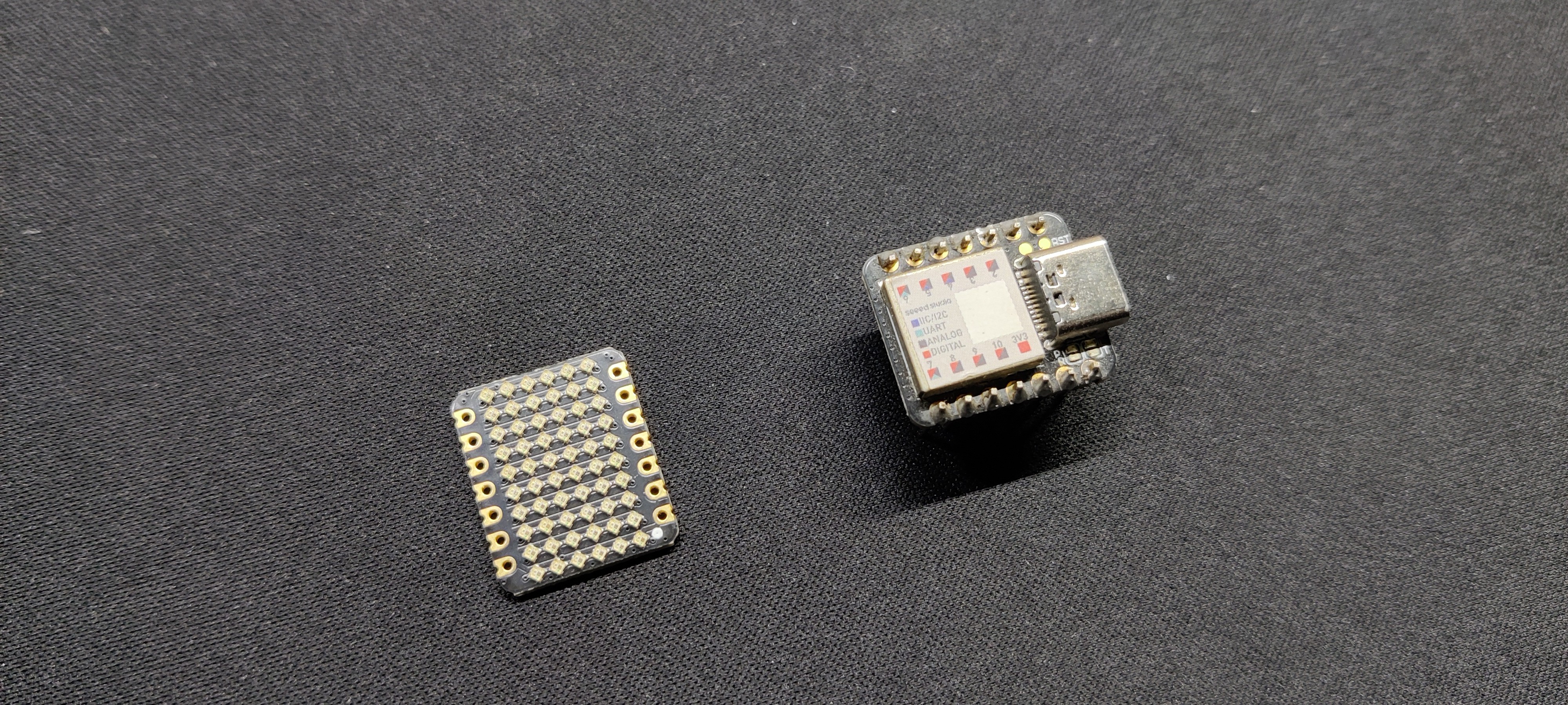
For this project, we're using the XIAO SAMD21 M0 Development Board paired with the XIAO RGB LED 6x10 matrix, which are both made by Seeed Studio.
The Seeed Studio XIAO SAMD21 is a compact and powerful development board featuring the ATSAMD21G18A-MU microcontroller, which is based on the ARM Cortex-M0+ architecture. This board is designed for low-power applications and is compatible with the Arduino IDE.
https://www.seeedstudio.com/Seeeduino-XIAO-Arduino-Microcontroller-SAMD21-Cortex-M0+-p-4426.html
We are using the XIAO RGB Matrix, which consists of 60 WS2812 LEDs arranged in a 6x10 grid, in addition to the XIAO SAMD21. This board is designed in a way that allows it to be directly linked to and controlled by any XIAO microcontroller. The user can easily link the board to any different setup thanks to the input and output connections provided on the bottom side of the board.
https://www.seeedstudio.com/6x10-RGB-MATRIX-for-XIAO-p-5771.html#...
Read more » Arnov Sharma


that's a pretty project :)