Hello hello,
When Alec mentioned an Infrared Communications SAO, one of the first things that came to mind is an old 90s TV Remote.
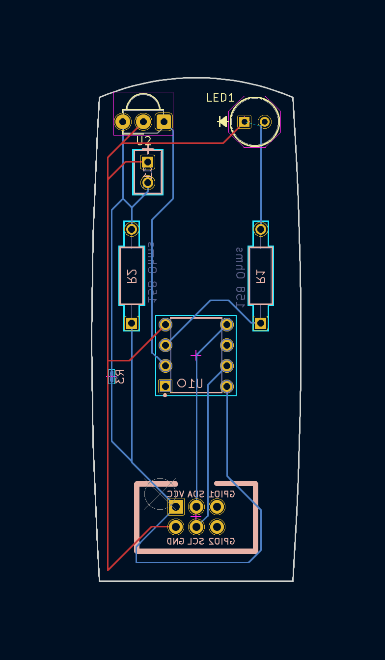
With that as an inspiration, I think I've gotten a reasonable shape down.

When discussing with Alec, we realized that technically the resister and capacitor for the IR receiver are optional. To give an option for testing, I've went ahead and added an R3 resister with 0 ohms in Kicad as a solder bridge point. The intention is to give a method to bypass the resistor and capacitor if needed.
This is my first attempt at designing a PCB and for using Kicad for that matter so I've been entertaining myself with learning all sorts of things.
More updates to come soon! :)
Discussions
Become a Hackaday.io Member
Create an account to leave a comment. Already have an account? Log In.