Hello again, another update from me!
I present:
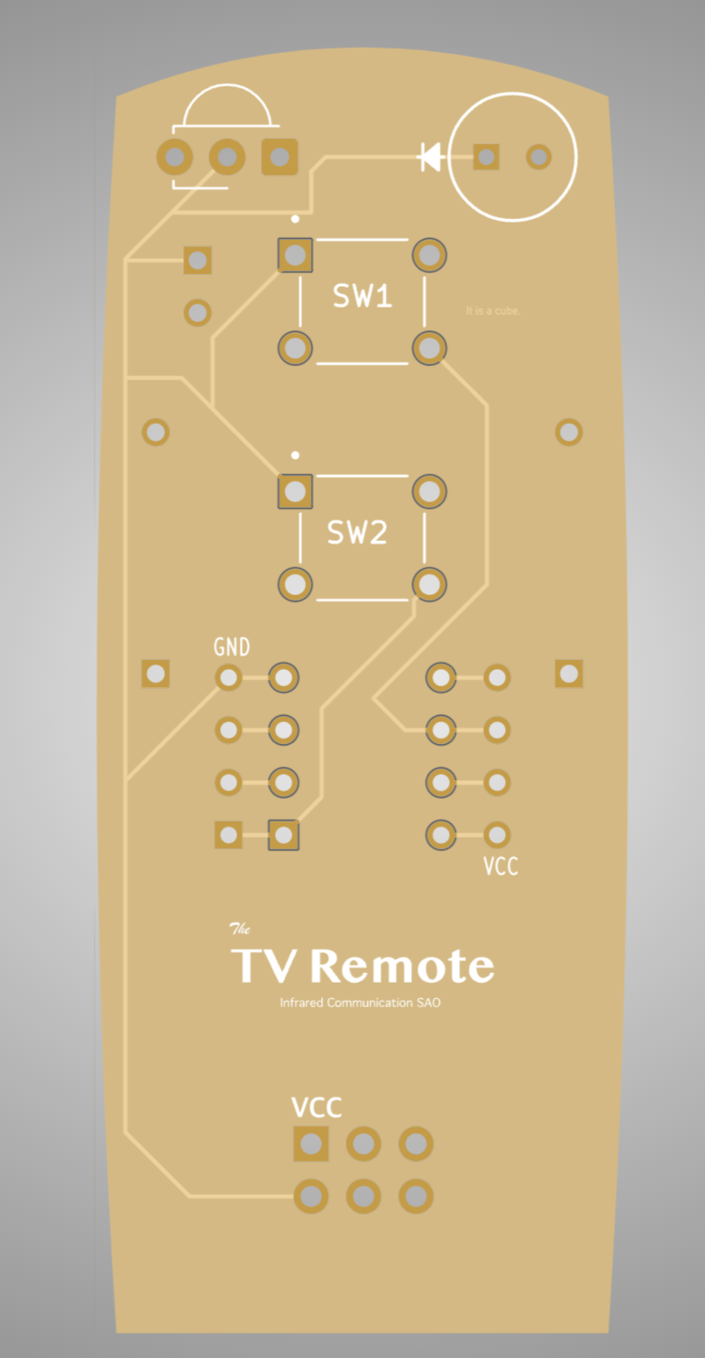
The TV Remote. Infrared Communication SAO.
A bunch of updates and changes with this updated so I decided I would go through them in sections.
Looks!
A bit more TV remoteness has been added to give a bit more of an TV remote appearance. Playing around with adding some fun things to the back of the PCB but will keep that hidden for now. ;)
If anyone has more suggestion on how to add to the "TV Remote"ness, please let me know!!!
Buttons!
A TV remote NEEDS buttons! I just so happen to have a couple hundred buttons laying around so things work would wonderfully.
Specifically buttons that look very similar to these:
https://www.digikey.com/en/products/detail/cui-devices/TS02-66-50-BK-260-LCR-D/15634249
(Granted, the ones I have are half a decade old and were from a random amazon seller... Should be fine.)
For now the buttons are connected to attiny85 pins 1 and 6 since the they unused.
This means by default the top button will act as a reset button. It is possible to change this behavior by setting a fuse in the attiny85 to use pin 1 as a normal pin. Something I will need to look into later.
Easy Hacking
A idea I wanted to implement as much as possible is expandability. This is an SAO first and foremost but, it is also at it's heart an attiny85. With that in mind I added optional pin headers to make accessing the attiny85 directly easy.

A few small things changed:
- Rerouted traces a bit
- Moved resister and capacitor jumper under the resister
Next Version
Of course as soon as I am done with this version, a few more nice to haves came out of conversations Alec and I had.
Specifically:
- Optional bridges for connection the GPIO1 and GPIO2 SAO pins to the attiny85.
- Labels for the optional resistor and capacitors associated with the IR receiver.
SMD Version
Now for the big shock (for me), as mentioned earlier Alec pointed out to me that actual rules of the SAO contest! Awkward, I missed those entirely!
Specifically, I missed the following:
- Within reason, design should avoid need for hand-soldering.
- SAO must not exceed a footprint of 2" x 1.5" (50 x 40 mm)
Our design:
- Does not use SMD components.
- Is 60mm x 25mm.
Luckily both are simple enough to fix, there should be enough room to shrink the height by 10mm. The components can also be switched to SMD which is something Alec and I are discussing now.
Part of the idea was this SAO would be something Alec and I could assemble ourselves and having through hole components makes that much easier. So I've decided to keep working on the existing version in parallel with a SMD version that will be within the design contest rules.
Discussions
Become a Hackaday.io Member
Create an account to leave a comment. Already have an account? Log In.