Close
0%
0%

PV Monitor and Divertor

To monitor the generation and hopefully use more of the electricity generated and eventually store some for later use

Similar projects worth following
A south facing 4kW array which works fine on its own, but how much is being generated? During last summer, not the best for sunshine, I noticed that the daily amount generated dipped during the peak of irradiance. Was this do to 1) poor summer, 2) midday sun going over the angle of the panels or, 3) panels overloading the inverter and not at maximum power point.

So I need a data logger and some sensors. and this is how it starts.

The setup

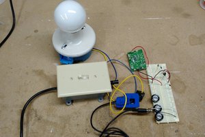
This is still in its development phase but the plan is to measure the power from the PV array, with a grid-tie inverter, and the power imported/exported from grid and to allow use of the excess generated power. This could go to a heater in workshop in winter or preheat water for the boiler. I have a combi boiler that allows preheat but this will need plumbing in. I had taken the old tank out, but kept it with much annoyance from the wife, planning ahead!?

Measurements

Do I count the pulses at the meter or measure voltage and current. For data logging purpose counting the pulses would be fine. Pulses over a fixed time (5 mins or 1 min) a trade off between amount of data and detail. Counting time between pulses may be too much detail.

Yet for power diversion this would probably not be accurate enough so voltage and current sampling will be needed. This then brings in the complication of phase correction as the samples are taken at different times.

Data logging

Should be simple.

Power diversion

This requires some more research on the control but in essence I switch a triac on and off so the meter does not charge me nor do I export any of my energy.

Power storage

Still to be considered but this will need battery banks, charge controller, inverter and a means of switching power sources. Also to be considered would be dedicated DC circuits in the house.
  • 1 × Arduino UNO
  • 1 × LM358 Amplifier and Linear ICs / Operational Amplifiers
  • 2 × IN4001 Rectifier Diodes
  • 1 × Transformer mains(240) to 6-0-6V 100mA
  • 3 × 10K ohm resistor

View all 6 components

  • First test to measure voltage and current waveform

    david02/09/2017 at 21:25 0 comments

    Using components I already have, hopefully without the need to purchase anything else.

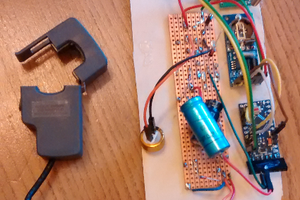
    The first current transformer (CT) was from an Ega energy monitor 71A - 25mA.

    No of coils = 71 / 0.025 = 2480

    The second CT purchased from eBay a YHCD SCT013 100A 50mA cost £7.91

    No of coils = 100 / 0.050 = 2000

    Burden resistor calculation

    CT1 = // PV - measured between inverter and consumer unit

    CT2 = // measured at my side of supply grid's meter

    Circuit is based in Robin Emerly's PV router mk2

    Tests run using his code with scripts: rawSamples.ino phase Checker and calPhase

    Calibration to follow.

View project log

Enjoy this project?

Share

Discussions

Similar Projects

Does this project spark your interest?

Become a member to follow this project and never miss any updates