 Anders Helgesson
In the last log entry I mentioned that there might be something wrong with my code as I cannot write to the first byte. I tried writing to it using the same function that writes to the reset register, but that doesn't work either.
There might be a problem with how the MCP2221A handles the command, the default address for the SLG46826V is 0x01, which is one of the reserved I2C addresses. Perhaps this could be the issue with the first byte. I could change the device's slave address and try writing again. For now, though, I'll continue working on the keypad matrix scanning design and revisit this problem later. I replaced that LUT with another LUT, and it seems to work fine.
I've soldered a socket header to the DIAVOX mainboard which can be used to attach wires to the SLG46826V.
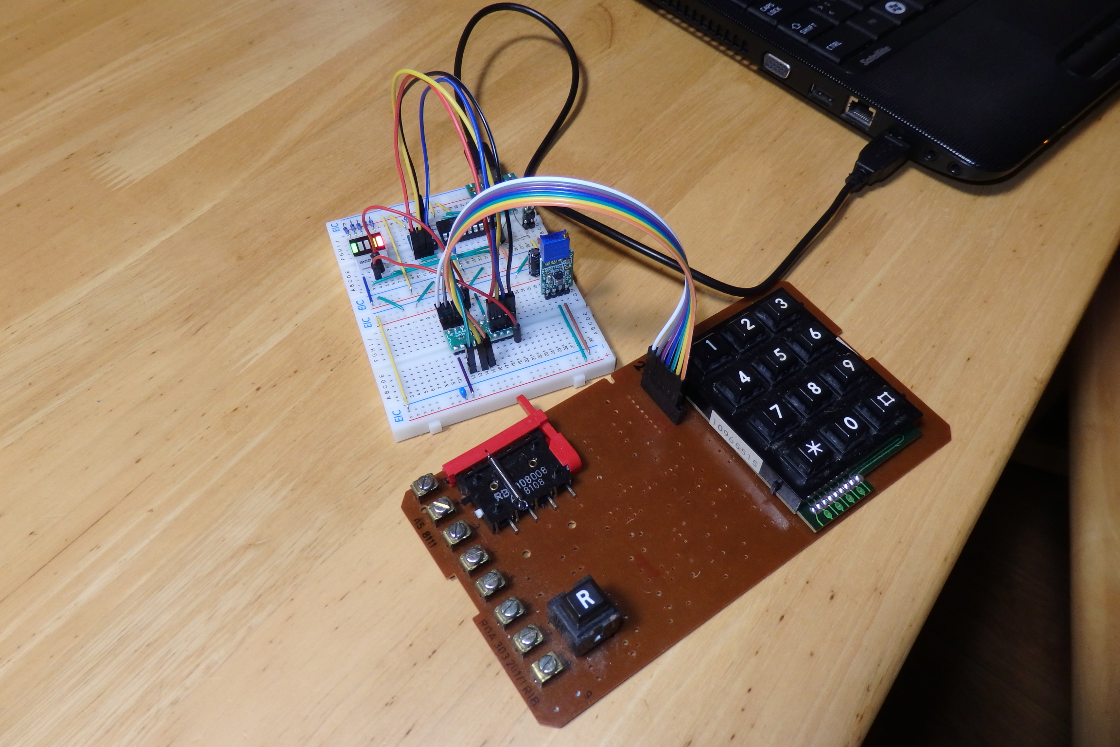
The SLG46826V should handle debouncing, disallow multiple keys from being held down simultaneously, and send the key pressed output signal. The pico could just read the registers via I2C to get which key is pressed. For now the key pressed signal will just be connected to a LED, so I can see that a key is being pressed. The keypad scanning part in the SLG46826V should be enabled/disabled by the handset switch. I'll probably have some resources left in the SLG46826V for some other purposes.
I referred to the design in the "AN-1113 Security Door Lock with Keypad Entry" application note and copied the design for the keypad matrix scanning.
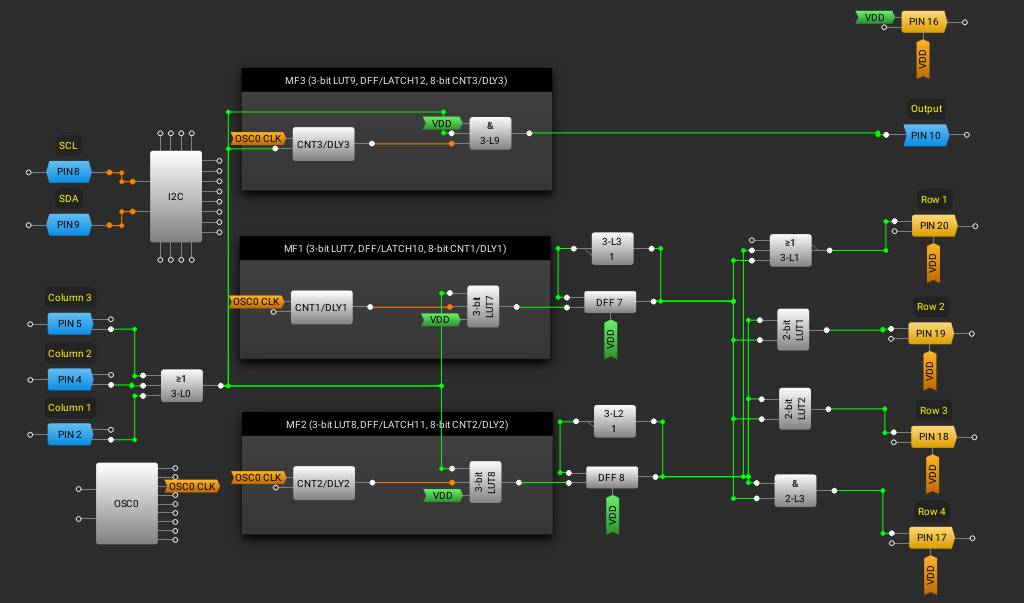
The keypad matrix scanning works perfectly. I added an output so I could tell when the SLG46826V have been programmed, for troubleshooting. If any of the keys are pressed an output signal is created. I just randomly selected the pinout, so I might readjust it later. I also need to add functionality to allow the scanning to be started or stopped using the handset switch.
I checked the output with my oscilloscope, and it looks solid.
Discussions
Become a Hackaday.io Member
Create an account to leave a comment. Already have an account? Log In.