 Anders Helgesson
Here is what the breadboard looks like now.
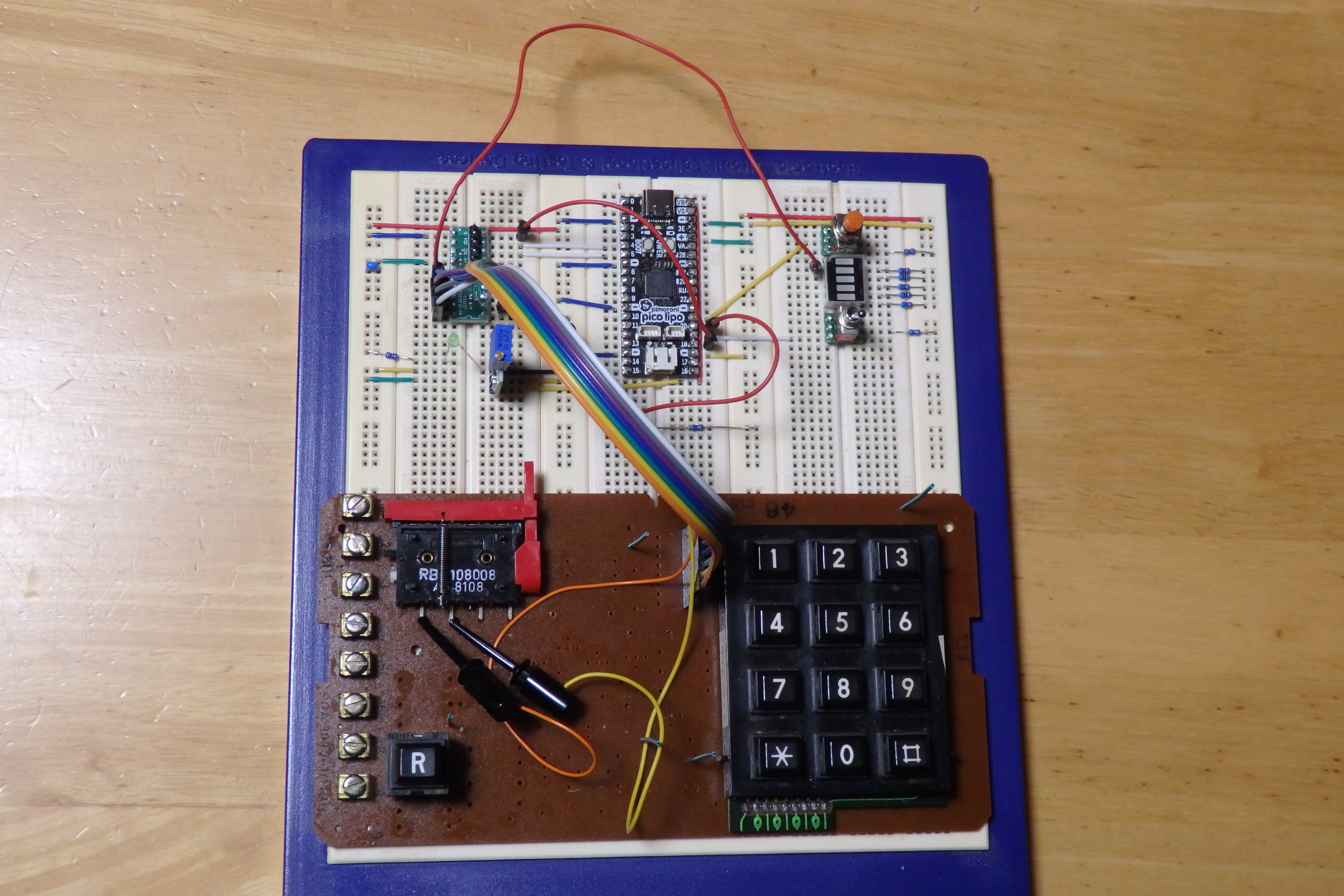
I pinned the DIAVOX mainboard onto the breadboard using solid core wire. It's connected to the SLG46826V module, which has been connected to the Pico Lipo via I2C and GPIO. The regulator powers the SLG46826V module, and I connected a LED so I can see that it is powered. I have two jumper wires from the SLG46826V module, one going to the keypad-matrix active and the other from programming good signal to a LED. The orange push-button have been connected as the R button and the toggle switch acts as the handset switch. The handset switch reset has also been connected.
With this set up, I can write the code for collecting the keys pressed and, troubleshoot the keypad matrix scanning design. I can also implement the reset switch functionality, collect the numbers pressed, switch states from user input to dialing, and turn off everything with the handset switch.
I mentioned before that I would use an ISR for the keypad active signal, but since we are only in the user input state when the handset is off, I've decided to just poll the signals. I might revisit this some other time if it could reduce power consumption.
I've implemented functions to check all of the newly added signals. Before powering anything up, I have to double-check all the connections. I will do that next time, as today's project time has run out.
Discussions
Become a Hackaday.io Member
Create an account to leave a comment. Already have an account? Log In.