 Anders Helgesson
This took longer than expected due to my knowledge gap in digital audio, misconceptions about stuff in general, and of course lack of time. I failed more times than I can count but I managed to figure it out, mostly.
So I had the assumption that I2C at 400khz should be able to playback clean simple tones easily, this was not correct including the communication overhead the practical achieveable sample rate is only 8khz. There is another problem, the DTMF which are two tones combined. You can have a LUT which has combined the two tones but it will not cleanly loop. I would need multiple cycles of each waveform until it both tones loop at the same time. You could also have two seperate luts for each tone and combining them before playback.
Looking at the LUT below, the DAC's 12bit resolution is not very usable at low sample rates.
pub const TONE_1633_HZ: [u16; 4] = [
    2047, 4009, 3162, 718
];
Only 4 samples for the 1633 Hz tone... It's not going to sound very nice.
I decided to use the Japanese dial tone at 400 Hz for testing. So I made a LUT at 8khz sample rate, it's only 20 samples.
pub const TONE_400_HZ: [u16; 20] = [
    2047, 2679, 3250, 3703, 3993, 4094, 3993, 3703, 3250, 2679, 2046, 1414, 843, 390, 100, 0, 100, 390, 843, 1414
];
I used the oscilloscope to measure the delay and adjusted it as close as possible to get 8khz playback. I get 397 Hz. But it doesn't sound like a sinewave for some reason. So I added a lowpass filter, since I lack a stock of various components I used two 10k resistors in parallel and a 0.01uf cap for the filter. Still doesn't sound like a sinewave.
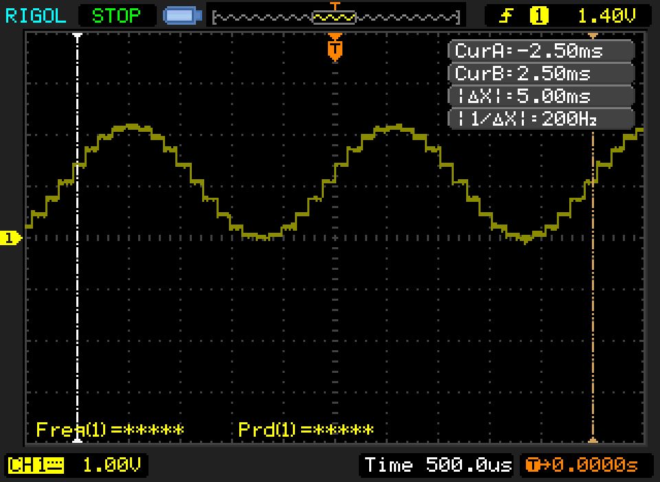
The signal looks like this from the DAC.
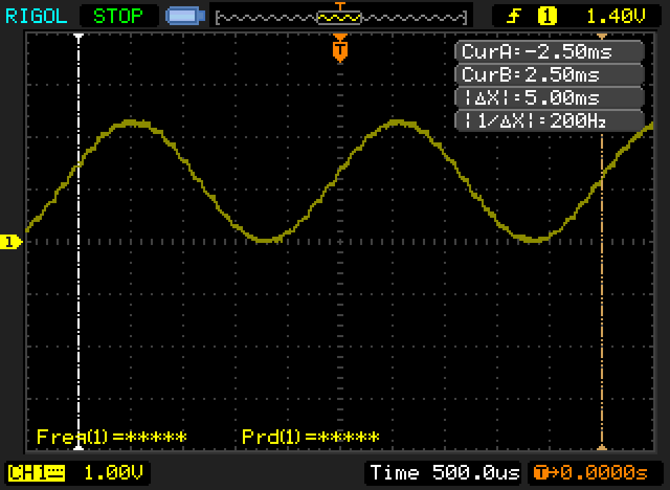
So I measured the signal before sending it to the pre-amp and then it looks like this, the filter does it's job.
The signal looks fine. Now measuring it after the pre-amp it looks like this. Now I guess I've connected something wrong to get this result.
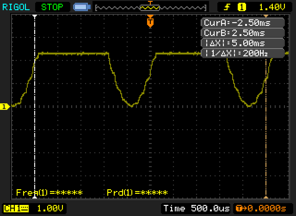
The voltage looks lower than it should be so I measured the output from the LDO and its only 2.4 volts and 2.7 volts at no load. I seemed to have damaged the LDO module while soldering or something, the pins and a piece of circuit board came off when I pulled on them. I've decided to solder a new LDO module. I'll put the broken one in the various parts bin, I could probably salvage the LDO when I get SMT tools.
When I get tone to output cleanly, I will rewrite it so the playback buffer is played using a timer instead, so I can get accurate 8khz playback. My current delay is not accurate enough.
Once I get this to work with the I2C DAC, I'm going to switch to PWM audio instead. This would give me a much higher sample rate with less components.
There is a way to use the I2C DAC at a higher sample rate, using high speed I2C at 3.4Mhz. This is not possible with the I2C inside the rp2040 as it only goes to 400khz, you would have to use PIO to send the data instead. Fast mode plus at 1mhz is supported in the rp2040 but that doesn't work with the MCP4726. I'm probably going to try PWM audio first, for learning it might be worth exploring the PIO approach though.
I'll try to write a log after each session but it's difficult since I always go overtime. I tend to get into the 'zone' and forget about everything else. Not very professional...
Discussions
Become a Hackaday.io Member
Create an account to leave a comment. Already have an account? Log In.