 Anders Helgesson
This is what the waveform looks like from the DAC with 3.3 volts this time.
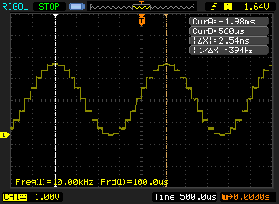
Looks good
This is what it looks like after the LPF(Low pass filter).
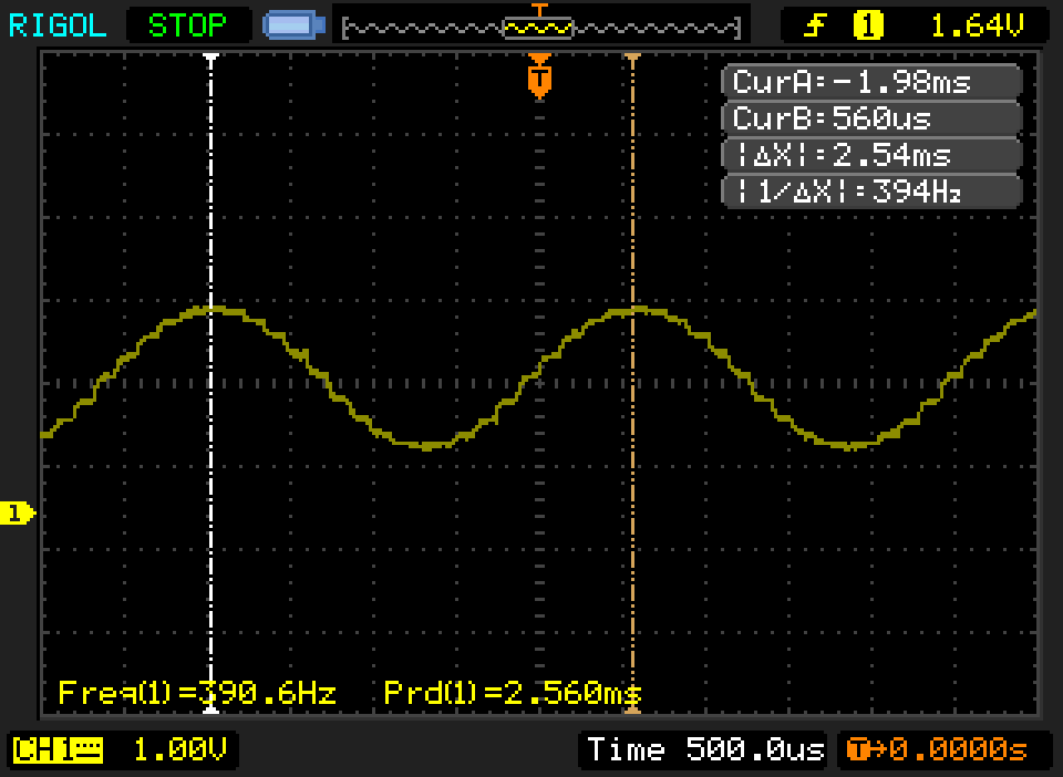
The waveform is cleaned up but it also drops in voltage, it's because of the voltage divider at the op-amp input.
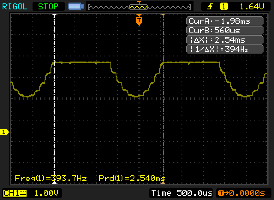
This is what it looks like after the pre-amp stage.

It's still being clipped...
This is what it looks like after the buffer.
Same, this is to be expected
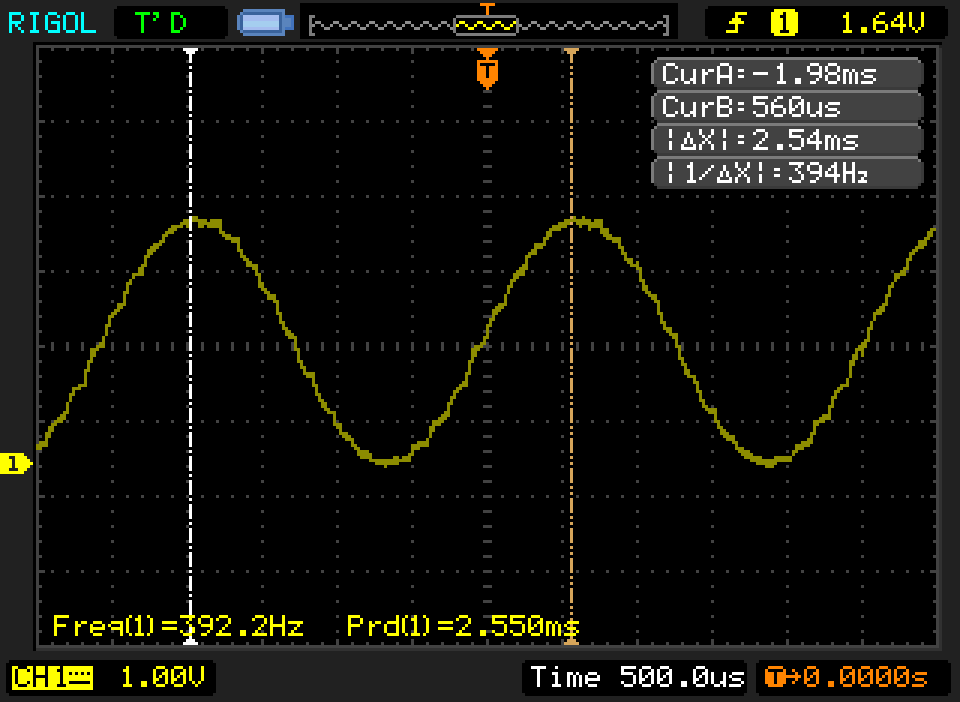
This is what the output looks like after the amplifer.
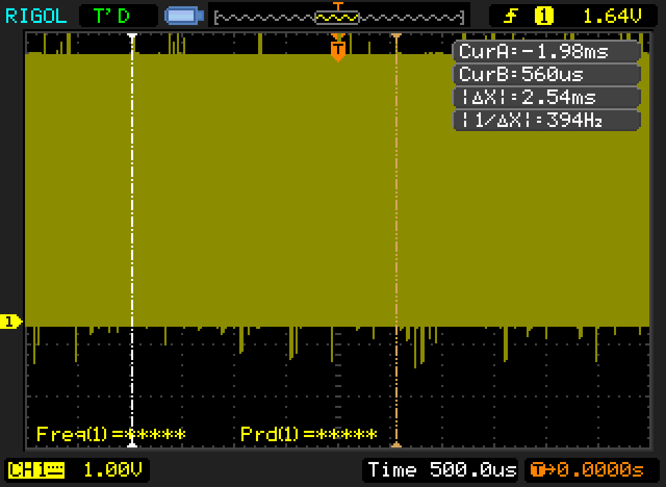
Okay..., the amplifer is powered from USB so that's probably where the noise comes from. I'll pretend I didn't see that and move on.
Okay, I'll remove the lowpass filter for now and the voltage divider at the pre-amp input. Now it looks like this.
Most of the time I don't know what I'm doing it seems that I'm trying to amplify a signal that doesn't need to be amplified... Stupid me... The DAC is already outputting at 3.3 volt. I do not need to amplify the signal further I could just use the buffer directly instead.
I removed the Pre-amp and put the filter back instead so now it's like this DAC -> LPF -> Buffer -> Amplifier -> Speaker.
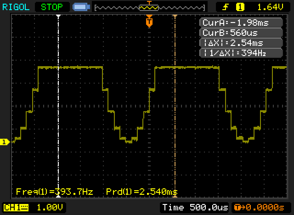
The signal after the Buffer now looks like this.
It sounds much much better. According to the oscilloscope I'm getting a 392.2Hz signal instead of the 400Hz I want. I need a better timer to handle the 8kHz playback.
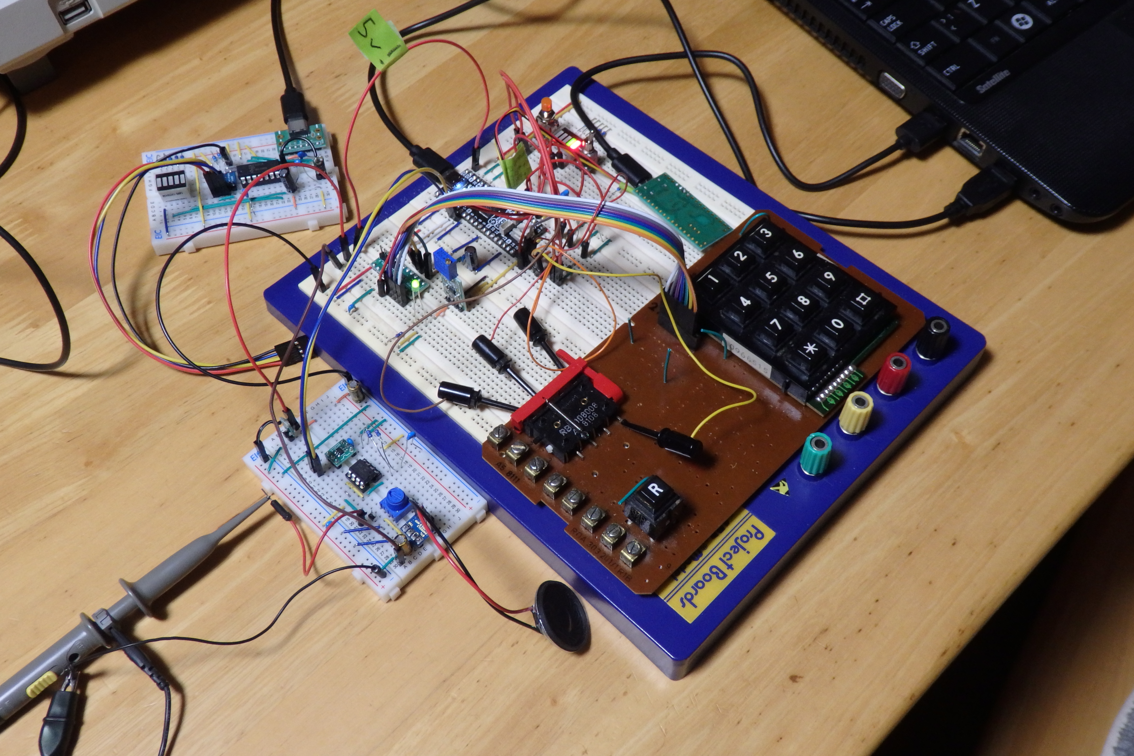
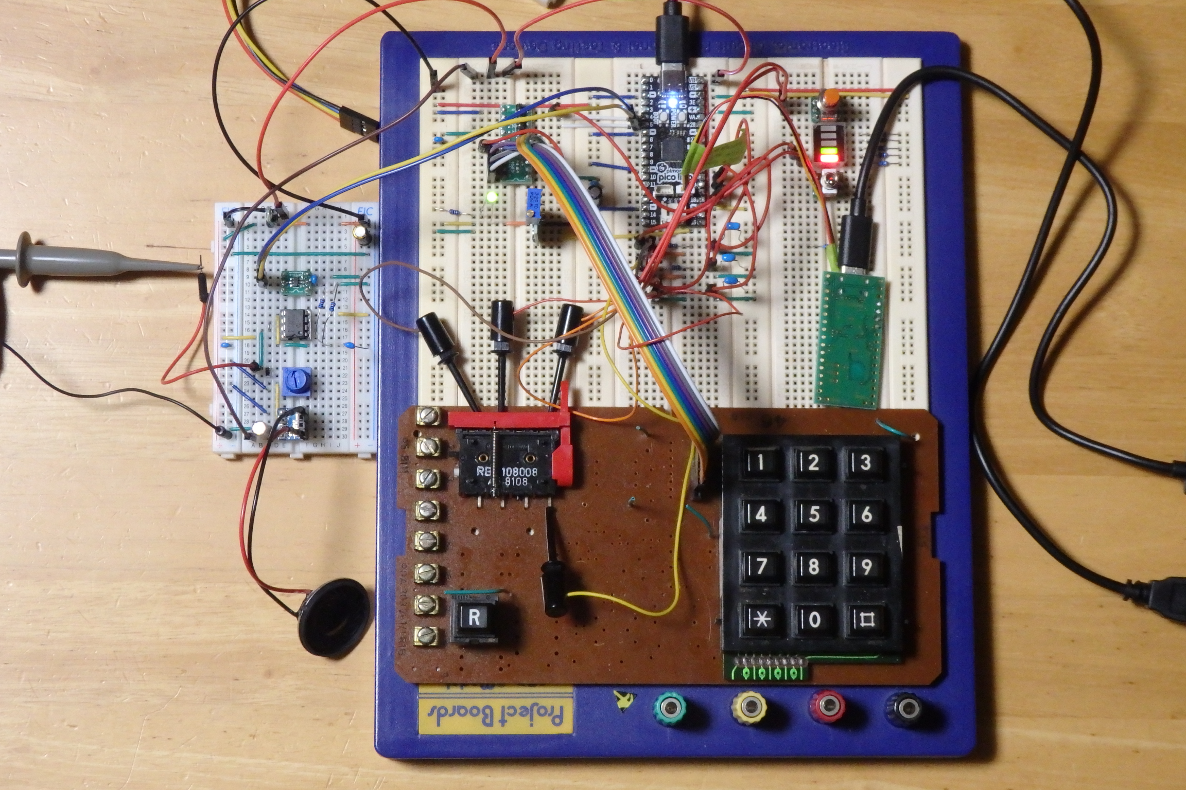
Here is some pictures what the breadboard setup looks like.
Today I took a different approach to writing the log, instead of writing a log entry at the end of the session, I updated the log entry as I went on. This seems to be better and also gives a bit of reflection what I'm doing. I'll probably continue doing this.
Discussions
Become a Hackaday.io Member
Create an account to leave a comment. Already have an account? Log In.