Self-assembly, PCB fabrication by JLCPCB. 2-layer PCB, lead-free HASL finish. C program for PIC18F2420 compiled with xc8. PICkit 3 used for programming and debugging.
More info:
This project uses a PIC18F2420 clocked at 4 MHz using the internal RC oscillator. I didn't want to have to spend money on an off-chip oscillator and determined that one was unnecessary anyway; I2C plays nicely with uncalibrated clocks thanks to its synchronous nature and nothing happening here is particularly time-sensitive. Timer0 is used here with a 1/256 prescaler to generate a 1.024 ms system tick. This system tick is used for everything time-related in this circuit, from scan rotation, to debouncing, and LED animations.
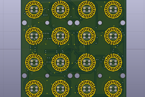
I used a 4x4 button matrix here for user input. The board layout is wild to accomodate the spacing and placement of the buttons, but it's such a low-speed circuit that I don't really care. It works pretty well: I used some nice tactile buttons with inline 1N4148 diodes to prevent ghosting and wired up 4 scan lines and 4 read lines to the PIC. The routine I wrote to handle user input works pretty well: every ~20 or so ms, the scan line changes (handled by interrupt) and the buttons read changes. I've found that this works very well combined with the debouncing routine I work that does a 5ms block after a button is pressed. To play nice with the interrupt-driven scan rotation, the user must depress the button for input to be registered.
A latched I2C constant-current LED driver is used for this project. Again, I didn't want to have to deal with Charlieplexing or driving the 16 LEDs with individual I/O ports. The PWM on the PIC18F2420 isn't great and I figured that I would rather have something that 1) can latch the current LED state and 2) give me variable brightness w/ PWM on every chip. This component (TLC59116) is very easy to use and works exceeding well - also lets me reduce the number of on-board resistors as biasing resistors are not required for this device (save for a 931 ohm resistor required to set a reference current). A 100 kHz I2C clock is used here. I set up two buttons on the button matrix to increase the duty cycle of the PWM brightness configuration using I2C commands. An LED refresh command is used to send I2C commands to update the LED state every time the game state changes.
Power input is through a microUSB AB jack. The LEDs would have made running this board off a battery very annoying as I'd go through many of them given the draw of these LEDs, so I made it convenient for prototyping/test as we have plenty of microUSB cords laying around.
The game state is probably not handled that efficiently, but I did my best to implement the game rules. So far, I've found no bugs worth noting.
Game implementation and miscellaneous notes:
There are silkscreen errors that I must fix but this is only a prototype/fun project.
LEDs without any "stones" in their pot will be off. LEDs with stones will be illuminated. The number of LEDs in each pot can be determined by pressing the button in front of each LED and counting the number of blinks. Pressing the previously-selected button again will move those rocks - but only if it is on the side of the current player's turn. Pressing a button on the other player's turn will only tell you how many rocks are in those pits.
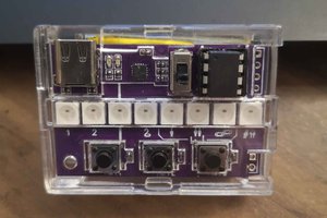
Global LED brightness can be adjusted by SW15 and SW16 on the PCB.
The reset circuit is activated by pressing SW17. Normally, the RESET pins on both the PIC18F2420 and TLC59116 are pulled to power through a 4.7K ohm resistor. Pushing SW17 will reset both chips and reset the game state.
The game is over when one player clears their side. The player who clears their side gets all outstanding rocks on the table placed in their mancala and the game is then decided by counting the number of stones in each mancala. At the end of the game, the player 1/2 LEDs will blink to indicate the winner. If there is a tie, both LEDs will blink. The reset button...
Read more » Zachary Murtishi
 Pierre-Loup M.
 mircemk
 Leon
Leon