Hardware
The schematic, Eagle and Gerber files can be found in my Github repository.
I placed the components underneath the LED matrix so they wouldn't be visible. I extended the width of the board to allow room for the button labels and to provide handles. The battery pack underneath is centered so that the weight of the assembly is centered. The end result is that it has a very nice feel to it - kind of like a Gameboy. I used surface mount buttons so that my fingers wouldn't get poked while holding the boards underside as they might if I had used through-hole buttons. As with many finished projects, the end design may seem obvious, but it wasn't at the beginning. It evolved slowly over time. I spent a lot of time, for instance, rearranging the button and LED locations for player convenience and visual aesthetic.
"Smart" LEDs
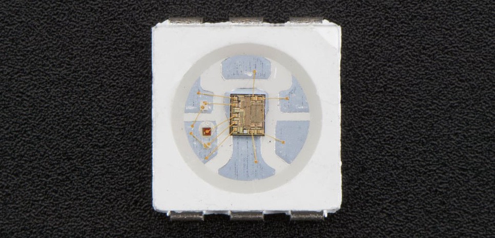
At the center of this project is the 8x8 LED Matrix. It uses WS2812B "smart LEDs." Smart LEDs embed logic circuitry that allow you to digitally control brightness of each of its internal red, green, and blue LEDs. The WS2812B is the most popular smart LED. You’ll find it used in most matrices and LED strips. I suppose they're popular because they are cheap and only use four pins (power, ground, data in, data out). But they are a bit of a pain to control because 1’s and 0’s aren’t represented by on an off, instead they are represented by different pulse widths. So, timing is critical. My code uses an entire SPI byte to send each bit. With SPI operating at 5 MHz, a byte value of 0x40 sends the shorter pulse width needed for a 0; 0x7C sends the longer pulse width needed for a 1.
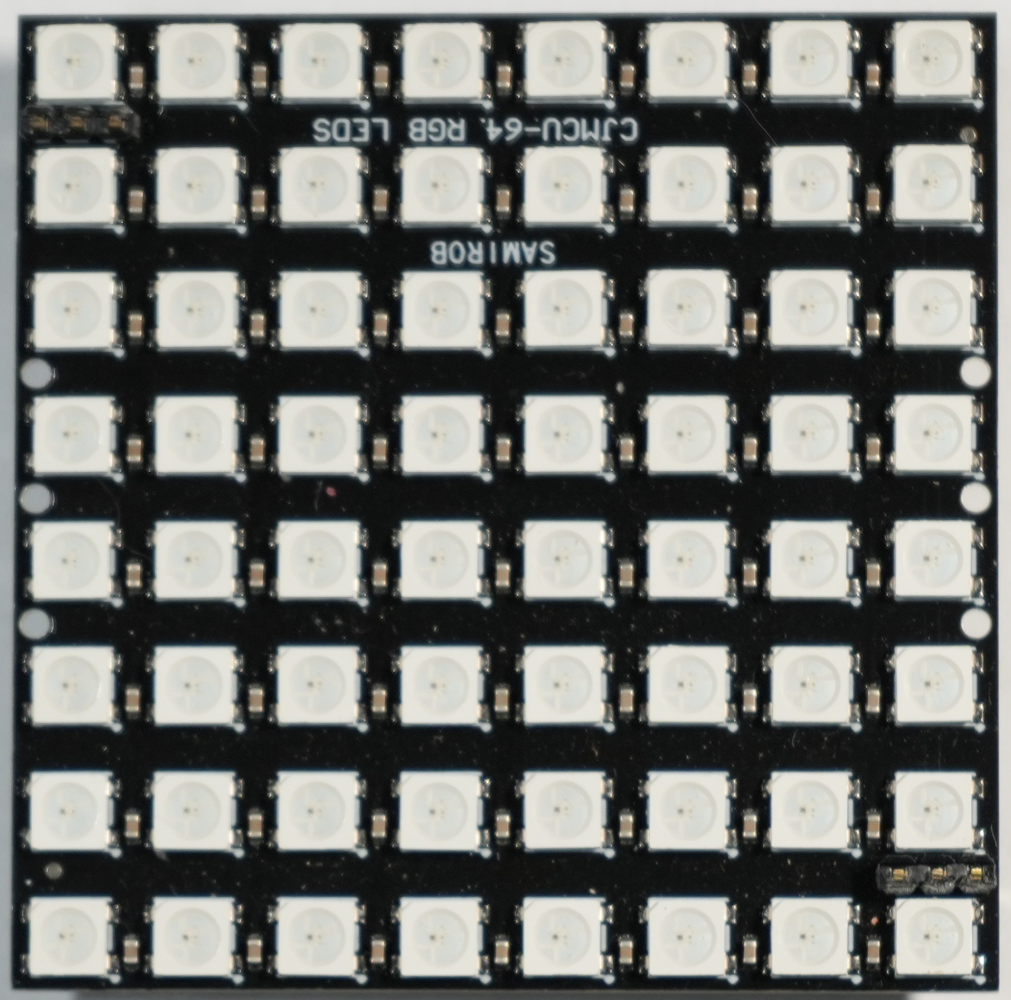
I bought my matrix on AliExpress. You can pay more to get one faster here. Or just search for "WS2812B 8x8". You'll find it in slightly different forms. If you want to use my board design, get one that matches the 3-pin header pads at the two corners.
My favorite smart LED is the HD107S. It adds two pins (clock in, clock out) for a total of six. These are super easy to control since timing is not at all critical. You can control it with SPI up to 30Mhz, or as slowly as you like. This project uses three of these and instead of SPI just bit bangs the 1s and 0s. That is, you set the data pin to high or low for 1 or 0 and then raise and lower the clock to "bang" out the bit. Like with the WS2812B, the LEDs are daisy chained. Once the first LED uses the first 32 bits, it ignores the next 32 bits while passing them through to the next LED and so on.
I love smart LEDs and use them often. You can get a pack of fifty HD107S on Aliexpress for $7.47. The SK9822 is a clone in the same package. Get them on Aliexpress or from AdaFruit. The only bad thing is they don’t come in a through hole version. To learn how to use them, I bought an LED strip so I wouldn’t have to solder them.
Microcontroller
This project uses the STM32L412KBT6. At $5.27 it comes with 128MB flash memory and 40k RAM and runs at 80Mhz. This project doesn't come close to using all that memory. I could have also used the STM32L412KBT6 that comes with 64MB flash for just $3.61. But I usually go with the most powerful version in the same package - just in case :).
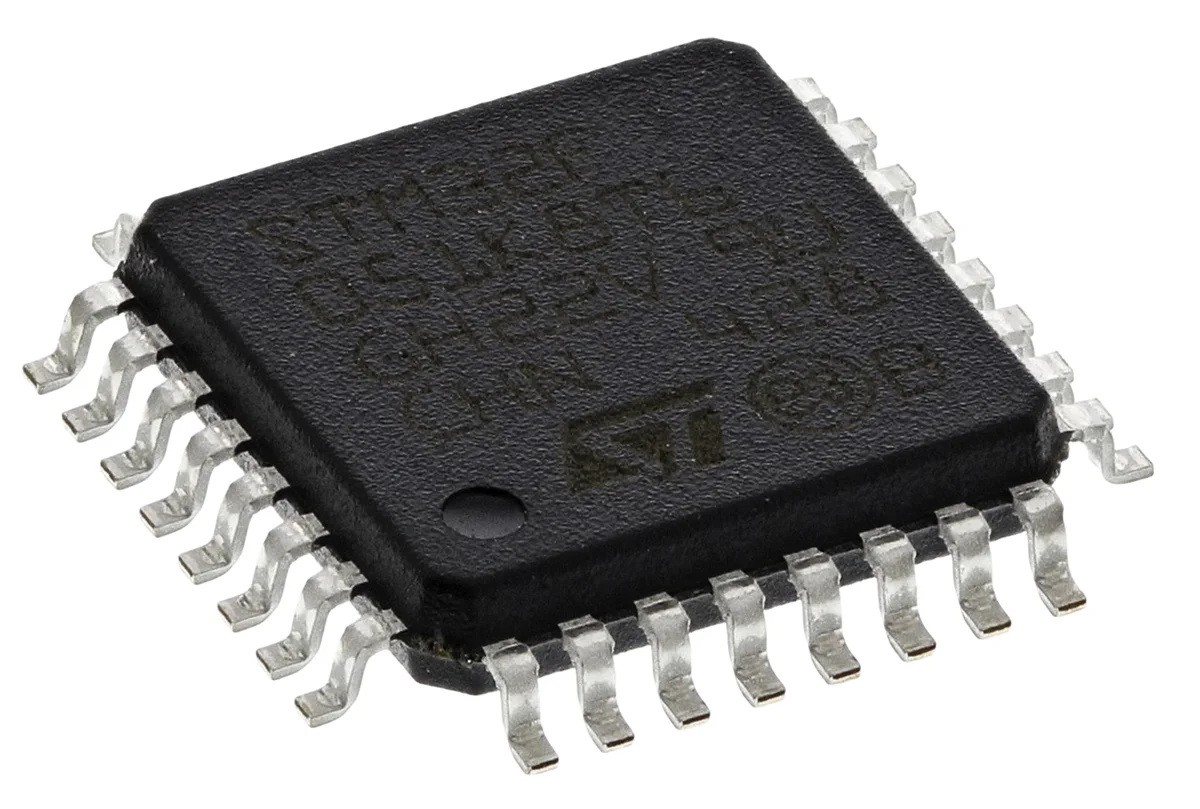
What drew me to the STM32 line of ARM Cortex microcontrollers, is the availability of powerful processors in an LQFP-32 package. Unlike larger pin packages, this one is pretty easy for me to solder. Plus, my projects don't usually need more pins than that.
Software
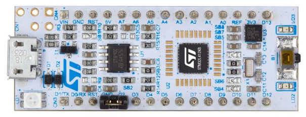
For programming the microcontroller, I use ST Microelectronic's completely free IDE called STM32CubeIDE. For only $10.99 you can buy the NUCLEO-L412KB shown below from Digikey. It and a micro USB cable is all you need to get started. And Digikey provides a fantastic getting started series.
Code Files
All the code can be found in my Github repository. The Readme in the software folder explains how...
Read more »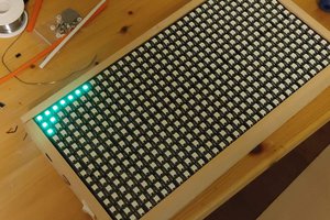
 Giulio Pons
 Yann Guidon / YGDES
 Leon
Leon